Garland E22 series User manual

Part # P66 (01/25/08) Page 1
Users are cautioned that maintenance and repairs must be performed by a Garland authorized service agent
using genuine Garland replacement parts. Garland will have no obligation with respect to any product that has been
improperly installed, adjusted, operated or not maintained in accordance with national and local codes or installation
instructions provided with the product, or any product that has its serial number defaced, obliterated or removed,
or which has been modified or repaired using unauthorized parts or by unauthorized service agents.
For a list of authorized service agents, please refer to the Garland web site at http://www.garland-group.com.
The information contained herein, (including design and parts specifications), may be superseded and is subject
to change without notice.
GARLAND COMMERCIAL INDUSTRIES
185 East South Street
Freeland, Pennsylvania 18224
Phone: (570) 636-1000
Fax: (570) 636-3903
GARLAND COMMERCIAL RANGES, LTD.
1177 Kamato Road, Mississauga, Ontario L4W 1X4
CANADA
Phone: 905-624-0260
Fax: 905-624-5669
Enodis UK LTD.
Swalloweld Way, Hayes, Middlesex UB3 1DQ ENGLAND
Telephone: 081-561-0433
Fax: 081-848-0041
Part # P66 (01/25/08) © 2006 Garland Commercial Industries, Inc.
FOR YOUR SAFETY:
DO NOT STORE OR USE GASOLINE
OR OTHER FLAMMABLE VAPORS OR
LIQUIDS IN THE VICINITY OF
THIS OR ANY OTHER
APPLIANCE
WARNING:
IMPROPER INSTALLATION, ADJUSTMENT,
ALTERATION, SERVICE OR MAINTENANCE
CAN CAUSE PROPERTY DAMAGE, INJURY,
OR DEATH. READ THE INSTALLATION,
OPERATING AND MAINTENANCE
INSTRUCTIONS THOROUGHLY
BEFORE INSTALLING OR
SERVICING THIS EQUIPMENT
INSTALLATION MANUAL
E22, E24, E18 & E20 SERIES ELECTRIC UNITS
PLEASE READ ALL SECTIONS OF THIS MANUAL
AND RETAIN FOR FUTURE REFERENCE.
THIS PRODUCT HAS BEEN CERTIFIED AS
COMMERCIAL COOKING EQUIPMENT AND
MUST BE INSTALLED BY PROFESSIONAL
PERSONNEL AS SPECIFIED.
INSTALLATION AND ELECTRICAL CONNECTION
MUST COMPLY WITH CURRENT CODES:
IN CANADA - THE CANADIAN ELECTRICAL
CODE PART 1 AND / OR LOCAL CODES.
IN USA – THE NATIONAL ELECTRICAL CODE
ANSI / NFPA – CURRENT EDITION.
ENSURE ELECTRICAL SUPPLY CONFORMS WITH
ELECTRICAL CHARACTERISTICS SHOWN ON
THE RATING PLATE.

Part # P66 (01/25/08)Page 2
IMPORTANT INFORMATION
WARNING:
This product contains chemicals known to the state of california to cause cancer and/or birth defects
or other reproductive harm. Installation and servicing of this product could expose you to airborne
particles of glass wool/ceramic fibers. Inhalation of airborne particles of glass wool/ceramic fibers
is known to the state of California to cause cancer.

Part # P66 (01/25/08) Page 3
TABLE OF CONTENTS
IMPORTANTINFORMATION..........................................2
GENERALINFORMATION............................................4
Uncrating........................................................................4
StatutoryRegulations............................................................4
RatingPlate......................................................................4
INSTALLATION......................................................4
E22SeriesInstallationOfBankingPlates ..........................................4
E24SeriesInstallationofBankingPlates...........................................4
CS22CounterStandInstallation ..................................................5
CS24CounterStandInstallation ..................................................5
Fryers–ModelE22-14F&E22-28FT ...............................................5
HotPlate–ModelE22-12H .......................................................6
Griddles–ModelE22-18G,E22-24G&E22-36G.....................................6
SandwichGriddle–ModelE22-18SG..............................................7
Food Warmers – Model E22-15W, E22-15WP, E24-32W & E24-32WP. . . . . . . . . . . . . . . . . .7
PizzaOvens–ModelE22-22P&E22-22PP .........................................8
Broilers–ModelsE22-12B,E22-24B&E22-36B.....................................8
HotPlate–ModelE24-12H .......................................................9
Fryers – Model E24-31F, E24-31SF, E24-31FBL, E24-31SFBL, E18F, E18SF,
E18FBL&E18SFBL................................................................9
Griddles – Model E24-24G, E24-36G, E24-48G, E24-60G & E24-72G . . . . . . . . . . . . . . . .10
StockPotsRanges–ModelE20-SP&E20-SPC....................................11

Part # P66 (01/25/08)Page 4
GENERAL INFORMATION
Uncrating
Carefully remove the units from the carton.
Remove all packing material from the units. On stainless steel
and brushed chrome units, the protective material covering
the stainless steel and brushed chrome should be removed.
Statutory Regulations
The installation and connection should comply with current
codes in Canada – The Canadian electrical code part 1 and /
or local codes. In USA – The National Electrical Code ANSI /
NFPA – Current Edition, and include
1. Switch panel size
2. Overload protection
3. Wire type
4. Wire size
5. Temperature limitations of the wires
6. Method of connection (Cable, Conduit, etc.)
Rating Plate
Ensure that the electrical supply conforms with the electrical
characteristics shown on the rating plate.
For serial plate location (showing voltage and loading), wall
clearances and required temperate ratings for supply cable,
refer to the section for the model being installed.
INSTALLATION
E22 Series Installation Of Banking Plates
All units may be installed independently or banked with
other E22 or G22 Series equipment. To ensure a matching
and permanent t between units, two banking plates are
available for each unit to be installed. One at the front and
one at the rear of each two units being banked together.
(If 2-1/2”(64mm) legs are supplied with the unit, discard
leveling bolts and replace with the 2-1/2”(64mm) legs.
1. Level each unit by adjustment of leveling bolts or legs.
Use a spirit level and level unit four ways; across front and
back and down left and right edges. Level all other units
to the rst unit.
Note: Griddles may not rest evenly on the unit body if
units are not leveled.
2. Remove sheet metal screws at rear of unit.
3. Attach one banking plate in position at rear by placing
the 1/4”(6 mm) diameter holes in the banking plate
over the screw holes in the rear of units and fasten by
replacing the sheet metal screws removed in Step 2.
4. Push units into position on counter top or back bar.
5. Remove lower front panels, by removing the acorn nuts
on each side of the panel. NOTE: CARE SHOULD BE TAKEN
WHEN REMOVING LOWER FRONT PANEL, SO THAT THE
WIRES ARE NOT DISENGAGED FROM THE SWITCHES OR
CONTROLS.
6. Place the second banking plate in position so that the
5/8”(16mm) diameter Holes in the banking plate t
over the lower front panel mounting bolts, with the 1/4”
(6mm) diameter holes in the banking plate at the bottom.
7. Secure the banking plate to both units, with the sheet
metal screws provided with the banking plates.
8. Replace and secure the lower front panels
E24 Series Installation of Banking Plates
All units may be installed independently or banked with
other E24 or G24 Series equipment. To ensure a matching
and permanent t between units, a front banking plate is
supplied with each unit. If 2 1/2”(64 mm) legs are supplied
with nit, discard leveling bolts and replace with 2 1/2”
(64 mm) legs.

Part # P66 (01/25/08) Page 5
1. Level each unit by adjusting leveling bolts or legs. Use a
spirit level and level unit four ways; across front and back
and down left and right edges. Level all other units to the
rst unit, securing each unit to the adjacent unit.
NOTE: Griddles may not rest evenly on the unit body, if
units are not leveled.
2. Remove upper front panel, by removing the acorn nuts
on each side of the panel.
3. Place the banking plate in position, over the two bolts
located in the main sides below the panel mounting
brackets.
NOTE: Install recessed (stepped) centre portion of
banking plate tight to the main sides of the units being
banked. Secure in place with two hex nuts supplied.
4. Replace and secure upper front panels.
CS22 Counter Stand Installation
1. Assemble and level counter stand as illustrated in the
instructions found in the counter stand carton.
2. Remove and discard leveling blots on the unit to be
install on the counter stand.
3. Place units in desired position on the counter stand,
securing the rst unit with the 3/8-16 machine screws
and at washers supplied with the counter stand. Insert
3/8-16 machine screws through the 9/16”(14mm)
diameter holes in stand into the leveling bolt weld nuts.
4. Connect banking plates as described in E22 Series
Installation of Banking Plates.
5. Secure last until to the counter stand with the 3/8-16
machine screws and at washers supplied with the
counter stand. Insert 3/8-16 machine screws through the
9/16”(14mm) diameter holes in stand into the leveling
bold weld nuts.
CS24 Counter Stand Installation
1. Assemble and level counter stand as illustrated in the
instructions found in the counter stand carton.
2. Remove and discard leveling bolts on unit to be installed
on the counter stand.
3. Remove the front and rear sheet metal screws in the main
bottom of units to be placed on the outer sides of the
stand.
4. Place units in desired position on the counter stand,
securing the rst unit with sheet metal screws removed in
paragraph 3. Insert sheet metal screws through the 9/32”
(7 mm) diameter holes in the stand into hole from which
the sheet metal screws were removed.
5. Connect banking plates as described in E24 Series
Installation Of Banking Plates.
6. Secure last unit to the counter stand with sheet metal
screws removed in paragraph 3. Insert sheet metal
screws through the 9/32”(7 mm) diameter holes in stand,
into the holes from which the sheet metal screws were
removed.
Fryers – Model E22-14F & E22-28FT
Serial Plate Location
The serial plate is located on inside of the main back, to
access remove fryer tank.
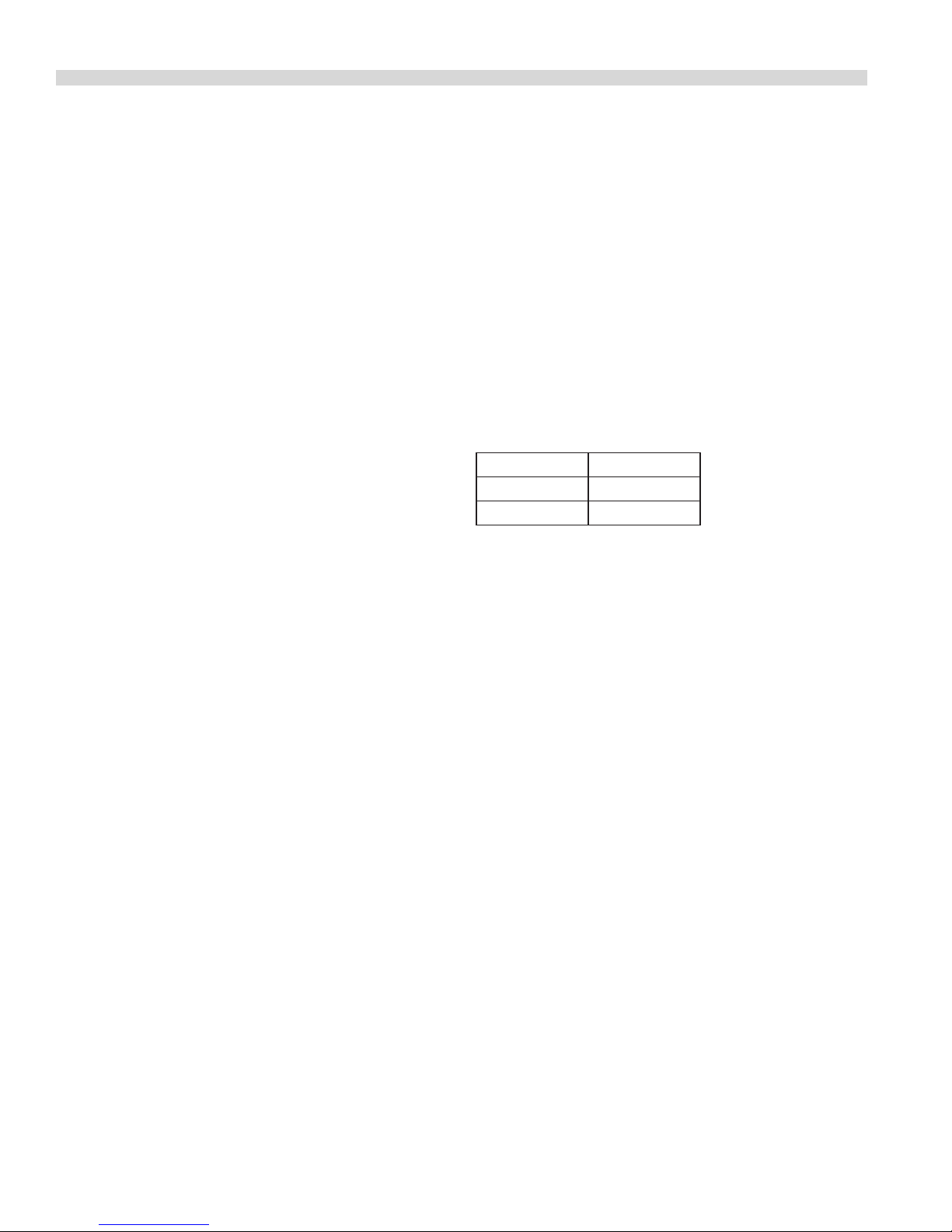
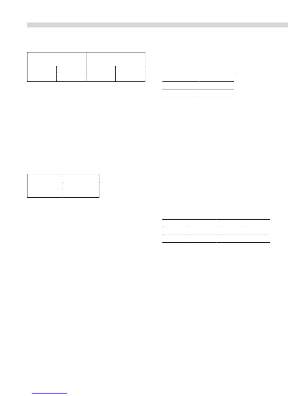
Wall Clearances
Do not install closer to a wall of combustible material than:
Sides 1/2”(13mm)
Back 1/2”(13mm)
Electrical Connection
For supply connection, use wire suitable for 75°C (167°F).
Electrical connection may be made though the knockout at
the rear of the unit in the terminal box located on the inside
of the rear of the unit. Access to the terminal box is gained
by removing the 10-24 machine screw and 10-24 hex nut
securing the terminal box cover to the terminal box.
To remove the fryer tank, raise the heating unit by means of
the handle until lock stop drops, holding the heating unit in
the upright position. The heating unit is lowered by moving
the lock stop to release the unit form the upright position.
Initial Operation
1. Before leaving the factory, the fryer was tested and the
thermostat calibrated with oil in the fry tank; therefore, it
is necessary to clean the fry tank before lling with frying
compound. Use detergent or other cleaning agents, with
hot water. Thoroughly rinse and dry fry tank. Fryer is now
ready to be lled.
2. If liquid frying compound is used, ll the tank to the ribs
stamped in the tank sides. Turn the thermostat to the
desired frying temperature.
INSTALLATION continued
This manual suits for next models
33
Table of contents
Other Garland Kitchen Appliance manuals

Garland
Garland GTOG12-2 User manual

Garland
Garland HO IN 1800 User manual

Garland
Garland GIU 2.5 User manual

Garland
Garland EDU-15HSE User manual

Garland
Garland GI-SH/GR 3500 User manual

Garland
Garland MERCO Savory MHC-22-TDL User manual

Garland
Garland MSTSR16-280 User manual

Garland
Garland Air-Deck G56T User manual

Garland
Garland GI-MO/QU 21000-720 Manual

Garland
Garland GAS PIZZA OVENS Manual