Garland HO IN 1800 User manual

Part # 4532286 Rev 3 (6/10/14) © 2013 Garland Commercial Ranges Limited
Models:
HO IN 450/ 900/ 350/ 1800
INSTALLATION AND
OPERATION MANUAL
GARLAND INDUCTION
TEMPERATURE CONTROLLED
BUILT-IN HOLD-LINE
with RTCSmp TECHNOLOGY
Real-time Temperature Control System
multi-point sensing
PLEASE READ ALL SECTIONS OF THIS MANUAL
AND RETAIN FOR FUTURE REFERENCE.
THIS PRODUCT HAS BEEN CERTIFIED AS
COMMERCIAL COOKING EQUIPMENT AND MUST
BE INSTALLED BY PROFESSIONAL PERSONNEL AS
SPECIFIED
INSTALLATION AND ELECTRICAL CONNECTION
MUST COMPLY WITH CURRENT CODES:
IN CANADA – THE CANADIAN ELECTRICAL CODE
PART 1 AND / OR LOCAL CODES.
IN USA – THE NATIONAL ELECTRICAL CODE ANSI /
NFPA – CURRENT EDITION.
FOR YOUR SAFETY
DO NOT STORE OR USE GASOLINE OR OTHER
FLAMMABLE VAPORS OR LIQUIDS IN THE VICINITY
OF THIS OR ANY OTHER APPLIANCE
CE models comply with the latest European Norms:
EN 60335-1, EN 60335-2-36, EN 62233 (EMC/EMV)
North American models: ETL listed in compliance
with UL 197, CSA C22.2 No.109, NSF-4
Complies with FCC part 18, ICES-001
WARNING
IMPROPER INSTALLATION, ADJUSTMENT,
ALTERATION, SERVICE OR MAINTENANCE CAN CAUSE
PROPERTY DAMAGE, INJURY, OR DEATH. READ THE
INSTALLATION, OPERATING AND MAINTENANCE
INSTRUCTIONS THOROUGHLY BEFORE INSTALLING
OR SERVICING THIS EQUIPMENT
Users are cautioned that maintenance and repairs must be performed by a Garland authorized service agent using only
genuine Garland replacement parts. Garland will have no obligation with respect to any product that has been improperly
installed, adjusted, operated or not maintained in accordance with national and local codes and/or installation instructions
provided with the product or any product that has its serial number defaced, obliterated or removed, and/or which has been
modified or repaired using unauthorized parts or by unauthorized service agents. For a list of authorized service agents
and/or genuine replacement parts, please visit our website at www.garland-group.com for USA and Canada. For
international customers, please visit www.manitowocfoodservice.com. The information contained herein, including design
and part specifications, may be superseded and is subject to change without notice.
Visit our Video Gallery at
www.Garland-Group.com

Installation and Operation Manual RTCSmp Built-In Temperature Controlled Hold-Line
2 Part # 4532286 Rev 3 (6/10/14)
WARRANTY
Our warranty statements for induction products are available on-line. Please visit our
website at www.garland-group.com/minisite/service to download the latest revision. If you
might have any questions, please contact Garland.
UNPACKING and PACKING SLIP
The packing slip attached to the shipment contains detailed information of all components.
Please retain this packing slip for future reference.
USING THIS MANUAL
This manual contains important information regarding safety, installation, operation,
maintenance, and troubleshooting. They must be read entirely and carefully by the
installers and operators before the equipment is installed and taken into operation. This
manual must always be available for reference at the place of operation.
Throughout this manual, the induction unit type “RTCSmp Heat Retaining Hold-Line” is
referred to as “induction unit”.
DESCRIPTION OF WARNING SYMBOLS
This symbol alerts you to a hazardous situation that WILL or COULD
cause serious bodily harm or death. Be alert and implement relevant
safety precautions.
This dangerous voltage warning symbol indicates a risk of electric shock
and hazards from dangerous voltage.
CAUTION
T
his symbol alerts a hazardous situation, which if not avoided, COULD
cause minor to moderate personal injury or property damage. The
relevant safety precautions MUST be implemented at all times.
Electromagnetic field.
To reduce the risk of fire or electric shock,
do not remove or open cover.
No user serviceable parts inside.
Refer servicing to qualified personnel.
CONTACTS
Garland Commercial Ranges Ltd. | 1177 Kamato Road, Mississauga, Ontario, Canada. L4W 1X4
T: 1-905-624-0260 | F: 1-905-624-5669 | www.garland-group.com
USA Sales, Parts and Service 1-800-424-2411
Canadian Sales 1-888-442-7526
Canada or USA Parts/Service 1-800-427-6668
International Sales and Service www.ManitowocFoodservice.com
Warning
Risk of fire or electric shock
Do not open

Table of Contents RTCSmp Built-In Temperature Controlled Hold-Line
Part # 4532286 Rev 3 (6/10/14) 3
WARRANTY .......................................................................................................................................................2
UNPACKING and PACKING SLIP ......................................................................................................................2
USING THIS MANUAL .......................................................................................................................................2
DESCRIPTION OF WARNING SYMBOLS...........................................................................................................2
CONTACTS.........................................................................................................................................................2
1Safety Requirements................................................................................................................................4
1.1Risk Involved By Disregarding Safety Information...........................................................................................................4
1.2Safety Instructions for Operator .............................................................................................................................................4
1.3Improper Use of the Equipment.............................................................................................................................................5
1.4Unauthorized Modification and Use of Spare Parts.........................................................................................................5
1.5Pan Detection................................................................................................................................................................................5
2Components and Features.......................................................................................................................6
2.1Application.....................................................................................................................................................................................6
2.1Components and Features .......................................................................................................................................................6
3Dimensions and Technical Specifications ..............................................................................................7
3.1Rating Plate....................................................................................................................................................................................7
3.2Nomenclature and Models.......................................................................................................................................................7
3.3Dimensions ....................................................................................................................................................................................7
3.4Electrical Specifications .............................................................................................................................................................7
3.5Operating Conditions.................................................................................................................................................................7
3.6Compliances ..................................................................................................................................................................................7
4Installation ................................................................................................................................................8
4.1Location...........................................................................................................................................................................................8
4.2Ventilation ......................................................................................................................................................................................8
4.3Electrical Compartment Protection.......................................................................................................................................9
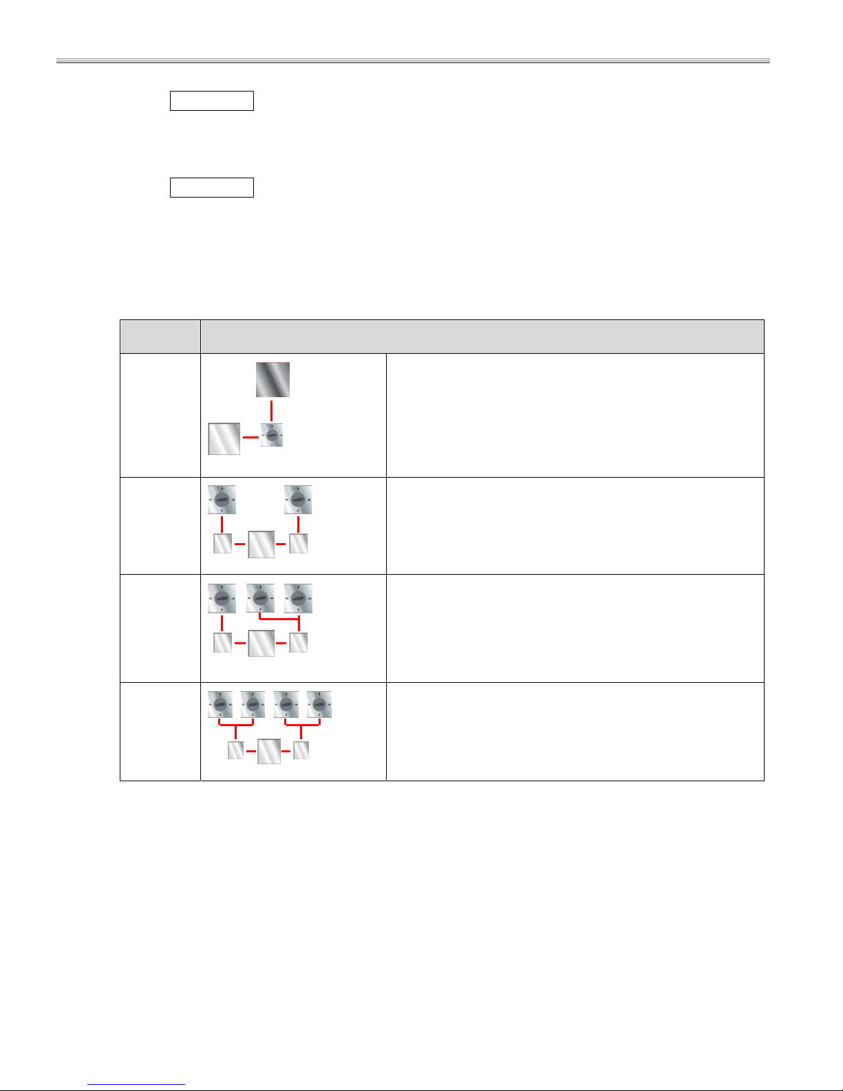
4.4Configurations ........................................................................................................................................................................... 10
4.5Dimensions and Installation.................................................................................................................................................. 11
4.5.1Heat Retaining Plate Installation ......................................................................................................................... 11
4.5.1.1Dimensions: RTCSmp HOIN450/900/1350/1800 Heat Retaining Plate 11
4.5.1.2Cut-Out Dimensions 11
4.5.1.3Parallel Installation and Clearance 12
4.5.1.4Installation Steps 13
4.5.2Control Unit Installation ......................................................................................................................................... 14
4.5.2.1Dimensions: Control Unit RTCSmp HOIN450/900/1350/1800 14
4.5.2.2Front-Mount 15
4.5.2.3Back-Mount 15
4.5.3Induction Generator Installation ......................................................................................................................... 15
4.5.3.1Orientation 16
4.5.3.2Mounting Methods 16
4.5.3.3Dimensions: Induction Generator RTCSmp HOIN450/900/1350/1800 16
4.6Electrical Installation................................................................................................................................................................ 17
5Function Test ..........................................................................................................................................19
6Operating Instructions...........................................................................................................................20
6.1Proper Induction Chafing Dish or Pan............................................................................................................................... 20
6.2Proper Placement of Chafing Dish or Pan on Single Hob........................................................................................... 21
6.3Temperature Control and Display....................................................................................................................................... 22
6.3.1Configurations and Temperature Control ....................................................................................................... 22
6.3.2Set and Current Temperatures............................................................................................................................. 23
6.3.3Digital Display............................................................................................................................................................ 23
6.4No Pan No Heat ......................................................................................................................................................................... 23
6.5When Unit is Not In Use.......................................................................................................................................................... 23
7Cleaning...................................................................................................................................................24
8Maintenance ...........................................................................................................................................25
9Important Rules ......................................................................................................................................25
10Troubleshooting.....................................................................................................................................26
10.1Common causes for induction unit failure ...................................................................................................................... 26
10.2Problems and Possible Causes............................................................................................................................................. 27
10.3Troubleshooting with Error Codes (for Service Technicians) .................................................................................... 28

Safety Requirements RTCSmp Built-In Temperature Controlled Hold-Line
4 Part # 4532286 Rev 3 (6/10/14)
1Safety Requirements
WARNING This product contains chemicals known to the State of California to cause cancer.
Installation and servicing of this product could expose you to airborne particles of glass
wool / ceramic fibers. Inhalation of airborne particles of glass wool / ceramic fibers is
known to the State of California to cause cancer.
IMPORTANT Warning labels mounted directly on the induction unit must be observed at all times and
kept in a fully legible condition.
IMPORTANT To ensure your working environment is safe, you must follow all of the safety instructions
contained in this manual, the existing national regulations for accident prevention with
electrical systems, as well as any relevant company-specific safety instructions.
T
he induction unit should only be used if and only if the
installation of the electrical system is fitted by an approved
installation contractor in accordance with specific national and
local regulations.
1.1 Risk Involved By Disregarding Safety Information
Disregarding the safety instructions may cause harm to people, the surroundings, and the induction unit. Garland
is not responsible for any damages or personal injury caused by failure to observe the safety requirements. Risks
involved when disregarding safety precautions may include:
Death or injury caused by electric shock.
Injury due to burns from contacting overheated chafing dish or pan or glass-top.
Damage to the induction unit caused by using unsuitable chafing dish or pan.
1.2 Safety Instructions for Operator
Please follow the following rules to avoid personal injuries and property damages:
When the unit is in use, heat transfers from the cookware to the glass-top; the glass-top can become hot. To
avoid burn injuries, do not touch the heating area when the unit is in use.
If the glass-top is cracked or broken, switch off the induction unit immediately and if possible and safe,
disconnect it from the power supply. Do not touch any parts inside the induction unit.
Persons with a cardiac pacemaker should consult their doctor whether they are safe near an induction unit.
If the power cord is damaged, have it replaced immediately by an approved service technician.
The induction unit heats up cookware quickly. Do not leave an empty pan on the unit and do not leave the
unit unattended during operation.
Do not put any other items on the glass cook-top except non-empty induction chafing dish or pan.
oDo not leave any object such as paper, cardboard, or cloth between the cookware and the cooking
surface, as this might start a fire.

Safety Requirements RTCSmp Built-In Temperature Controlled Hold-Line
Part # 4532286 Rev 3 (6/10/14) 5
oMetallic objects are heated up very quickly when placed on the induction unit when the unit is in
use. Do not place any objects such as closed cans, aluminum foil, cutlery, jewelry, or watches on the
induction unit.
oDo not place credit cards, phone cards, tapes, or any objects sensitive to magnetism on the cooking
surface.
oDo not place plastic vessels and aluminum objects such as aluminum foil on the glass-top.
Ensure liquid cannot enter into the induction unit. Do not let water or food overflow the cooking area. Do not
use hoses to clean or power wash the induction unit or its vicinity.
The induction unit has an internal air-cooling system. Do not block the air intake and exhaust openings with
objects such as cleaning cloths or containers. Any obstruction to the air intake and exhaust could cause the
unit to overheat and to switch off.
Switch the unit OFF if you take the chafing dish or pan away for a while. This will prevent the heating process
to start automatically and unintentionally when a pan is placed back on the heating area. If any person needs
to use the induction unit, he/she will have to turn the unit ON intentionally.
Use only induction suitable chafing dishes or pans with proper sizes and made of proper material. The
induction suitable serving dishes or pans should also be in good condition without any uneven, arched or
partially detached bottoms.
1.3 Improper Use of the Equipment
The reliability of the induction unit can only be guaranteed when it is used properly. The induction unit must
always be operated within the limits provided in the technical specifications. Please refer to section 9 Important
Rules of using induction equipment.
1.4 Unauthorized Modification and Use of Spare Parts
Please contact the manufacturer if you intend to make any changes on the induction unit. For safety reasons,
always use genuine parts and accessories approved by Garland. Any unauthorized modification as well as any
installation of unapproved components will void all warranty. See Warranty, p.2.
1.5 Pan Detection
Energy is transferred to cookware when the induction system detects a suitable pan on the heating area. The
digital display signals to communicate the Pan Detection process.
When the unit is ON without any pan on the hob, the display shows the current temperature without a
dot; the unit is in pan detection mode.
As soon as a pan is put on the hob, the heating process is engaged and the display shows the current
temperature followed by a blinking dot.
However, if the unit is not detecting any pan, the current temperature is shown without a dot.
NOTE: Pan with a bottom diameter smaller than 5” (12 cm) is not detected by the system.

Components and Features RTCSmp Built-In Temperature Controlled Hold-Line
6 Part # 4532286 Rev 3 (6/10/14)
2Components and Features
2.1
Application
The RTCSmp Install Hold-Line units are specially designed as built-in equipment for closed counters. These units
are ideal for buffets, events and banqueting, providing constant and precise temperature to ensure top quality
food presentations and appeal. The RTCSmp Install Hold-Line model offers four configuration options; a single
generator can power up to four hotplates. Temperature adjustment within a large temperature range (122-212
o
F
/ 50-100
o
C) allows for flexibility and precise food temperature requirements. To guarantee the induction units’
reliability and performance, please observe all safety, installation, and operation requirements mentioned in this
manual.
2.1
Components and Features
Built with a robust construction, the RTCSmp Induction Hold-Line unit is
modular and powerful with the revolutionary RTCSmp-Technology (Realtime
Temperature Control System with Multi-Point sensing). The RTCSmp Technology
monitors the energy supply, the state of the induction coil, power board, CPU,
and the cooking zone in realtime. RTCSmp also limits the energy supply during
peak load and its special control eliminates interference noises.
The RTCSmp Hold-Line models include a number of components which allow
for optimal flexibility in designing an efficient kitchen. The unique features of
each component are outlined below. See also chapter 3 Dimensions and
Technical Specifications.
Induction Generator:
Engineered specifically for heat retaining applications. | All connections are
accessible from the front of the housing. | Closed aluminum housing with
integrated cooling fan to keep electronics cool. | Integrated air guiding system
to direct exhaust air out of the housing on its left and right sides.
Heat Retaining Plate:
Compact and flat profile to allow for flush mounted installations in shallow
cabinets. | High impact Ceran glass-top with a highly visible digital display
beneath to show the set and the current temperatures. | Included: Coil and
Sensor Cables.
Operation Unit:
Each control switch consists of a chrome sheet metal cover with a built-in power
switch, enclosed in a strong, polymer housing. | Control units are separately
mounted; each comes with a 118” (3000mm) RJ-45 cable. | The control unit
regulates the temperature in an increment of 5
o
F(1
o
C), from 122-212
o
F / 50-
100
o
C. | Simple to operate. Adjust the temperature setting simply by turning the
knob.

Dimensions and Technical Specifications RTCSmp Built-In Temperature Controlled Hold-Line
Part # 4532286 Rev 3 (6/10/14) 7
3Dimensions and Technical Specifications
3.1 Rating Plate
T
he rating plate specifies important information such as model number,
serial number, and electrical specifications. The rating plate is affixed to
the bottom of the generator, by the connectors at the front.
3.2 Nomenclature and Models
Series Built-In Power (Watt) Model
HO = Hold Line IN
450 (1 heat-retaining plate) HO IN 450
900 (2 heat-retaining plates) HO IN 900
1350 (3 heat-retaining plates) HO IN 1350
1800 (4 heat-retaining plates) HO IN 1800
3.3 Dimensions
Component Dimensions (width x length x height)
Generator Housing 11.93”x 12.28”x 5.31” (303 x 312 x 135mm)
Heat-Retaining Plate 12.68”x 12.68”x 2.95” (322 x 322 x 75 mm)
Ceran Glass 12.68”x 12.68”x 0.16” (322 x 322 x 4 mm)
3.4 Electrical Specifications
Model Voltage Power Power Per Heating Plate
HOIN450/900/1350/1800 120 V AC / 1Ph 1800 W / 16A 450W
HOIN450/900/1350/1800 230 V AC / 1Ph 1800 W / 8A 450W
3.5 Operating Conditions
Max.
T
olerance of Nominal Supply Voltage +6 /-10 %
Supply frequency 50/60 Hz
Ingress Protection class IP X0
Minimal Diameter of Induction Pan 5” (12cm)
Maximum Ambient
T
emperature In Storage > -4°F to +158°F (-20°C to +70°C)
In Operation >+ 41°F to +104°F (+5°C to +40°C)
Maximum Relative Air Humidity In Storage > 10% to 90%
In Operation > 30% to 90%
Set Temperature Range 122-212°F
/
50-100°C
Maximum air flow: 56.50cfm / 96m3per hour and min. opening: 9.30 sq.in. / 6000mm2is required.
3.6 Compliances
North American models:
ETL listed in compliance with UL 197, CSA C22.2 No.109, NSF-4. Complies with FCC part 18, ICES-001
CE models comply with the latest European Norms:
EN 60335-1, EN 60335-2-36, EN 62233 (EMC/EMV)

Installation RTCSmp Built-In Temperature Controlled Hold-Line
8 Part # 4532286 Rev 3 (6/10/14)
4Installation
IMPORTANT
Kitchen designers and installation contractors are responsible for designing and installing correctly the
appropriate support structures and ventilation system for the cooking equipment.
When designing kitchen cabinets for the induction equipment, please take into account all installation
requirements, including factors such as: ease of electrical installation, size of the power conductor, and
length of the wires.
The installation, including electrical installation, must be carried out by registered installation contractors
only. The contractors are responsible for interpreting all instructions correctly and performing the
installation in compliance with national and local regulations. The warning signs and rating plates on the
cooking equipment must strictly be followed.
Read ALL SECTIONS carefully, comply with all requirements listed and ensure all inspection is done by
qualified personnel.
Refer to the technical data given in chapter 3 Dimensions and Technical Specifications.
Induction equipment that is not installed correctly will have warranty voided. See Warranty, p.2.
4.1 Location
The induction unit must be installed securely in closed counters. IMPORTANT: Allow easy access to unit
and cable connections for maintenance and service.
The heat retaining plate has to be mounted on a leveled and even counter surface.
The generator can be placed in a separate cabinet. All the connectors are located at the front.
CLEARANCE minimum 2.95”(75mm) for the connectors. Ensure the generator and connectors can be
accessed easily for electrical installation and service.
Do not place the induction unit on or near a hot surface or any heat producing equipment such as an
oven or a deep fryer.
Protect the induction unit from steam if the unit is placed next to high steam emitting equipment such as
pasta cookers, steamers, and water bath.
Allow easy access to the control knob(s).
Keep the induction unit away from combustible materials, vapors or liquids.
4.2 Ventilation
Proper cool air intake and ventilation is essential to the reliability and functioning of the induction unit. Please
ensure all requirements listed below are met:
The air intake and exhaust openings of the Generator must not be blocked. CLEARANCE: minimum 1.57”
(40mm).
The maximum air flow is 56.50cfm (96m3per hour) and therefore a minimal opening of 9.30 sq.in. (6000
mm2) is required.
An optimal air intake must not be restricted by the installation.

Installation RTCSmp Built-In Temperature Controlled Hold-Line
Part # 4532286 Rev 3 (6/10/14) 9
Ensure the induction unit always gets cool air intake. If necessary, draw in fresh air supply through an air
duct (not provided).
When installing the built-in unit, ensure the intake air and exhaust air are conducted separately. The in-
take air and exhaust air must not mix. To avoid build-up of hot exhaust air inside the cabinet, draw the
exhaust air out of the cabinet. Build up of hot exhaust air will cause the induction unit to reduce power
or to switch-off. The air intake temperature must not exceed 104F (40C).
We recommend drawing fresh intake air through an air intake vent with a removable air intake filter.
It is highly recommended that an exhaust fan be installed into the cabinet at an appropriate location.
This will force hot air out the cabinet and away from the induction unit. Consult an electrical or
installation expert for the most appropriate location to install a cabinet exhaust fan.
4.3 Electrical Compartment Protection
To protect the equipment, isolate the unit and the wires in a separate electrical compartment inside the cabinet.
The illustrations below show two installation versions.
Figure (A) The unit is installed in one compartment and the wires are exposed.
Figure (B) The interior space of the cabinet is divided and the unit and the wires are protected inside
separate compartments. Extra storage space is also created next to the electrical compartments.
(C) IMPORTANT Fresh air intake through the fan. It is recommended to isolate the
fresh air intake from the exhaust air via an air intake duct and filter the intake air
with a removable air filter. (see example on right)
(D) Hot air exhaust from the induction unit.
(E) IMPORTANT Air exhaust opening installed on the cabinet. It is highly
recommended to install a fan or fans on the cabinet to pull the hot exhaust air
away from the electronic equipment. Buildup of hot exhaust air will cause the
induction unit to reduce power or to switch-off. The air intake temperature must
not exceed 40C / 104F.
(F) IMPORTANT Minimum clearance for electrical connections: 75mm / 2.95”
(G) IMPORTANT Minimum clearance for air-exhaust outlets: 40mm / 1.57”
Figure
B
Figure
A
H
E
D
J
I
F
G
D
C
H
E
D
J
I
F
G
D
C
Air Intake Filter
Filter Holder
Filter Holder

Installation RTCSmp Built-In Temperature Controlled Hold-Line
10 Part # 4532286 Rev 3 (6/10/14)
(H) IMPORTANT Minimum clearance for heat plate under counter surface: 100mm / 3.94”
(I) Cable for operation unit connecting to the induction generator, MAX 300cm / 118”.
(J) Cables for coil and sensors.
IMPORTANT Always route sensor and communication cables separately and away from the coil cables.
4.4 Configurations
One Induction Generator can power up to four (4) Heat Retaining Plates. You need to install two (2) control units
for any configurations with 2 to 4 Heat Retaining Plates.
Model Configuration
(Heat Retaining Plate(s), Control Switch(s), and Induction Generator are shown)
HO IN 450
One switch controls one heat retaining plate.
One (1) heat retaining plate, one (1) generator and one (1)
control unit.
HO IN 900
Two switches; each controls only one heat retaining plate.
Two (2) heat retaining plate, one (1) generator and two (2)
control units.
HO IN 1350
Two switches; one switch controls one heat retaining plate and
the other switch controls two plates.
Three (3) heat retaining plate, one (1) generator and two (2)
control units.
HO IN 1800
Two switches; each controls two heat retaining plates.
Four (4) heat retaining plate, one (1) generator and two (2)
control units.

Installation RTCSmp Built-In Temperature Controlled Hold-Line
Part # 4532286 Rev 3 (6/10/14) 11
4.5 Dimensions and Installation
4.5.1 Heat Retaining Plate Installation
The Heat Retaining Plate is to be flush-mounted. A support frame or support structure has to be custom designed
and built for housing the retaining plate(s).
4.5.1.1 Dimensions: RTCSmp HOIN450/900/1350/1800 Heat Retaining Plate
(measurements in mm and [inch])
4.5.1.2 Cut-Out Dimensions
Please review carefully the dimensions in section 4.5.1.1.
Refer to Detail A in section 4.5.1.1:
A. Cut-out dimension on the counter surface: 330 x 330mm [12.99” x 12.99”].
NOTE: Dimensions include widths for silicone joints on all four (4) sides.
Consider adjusting cutout dimensions based on mounting methods, see 4.5.1.3.
B. Recommended recess depth: minimum 8.00 to 8.64mm [0.315”to 0.34”].
C. Body Clearance (width x depth x height): 300 x 300 x 100mm / 11.81” x 11.81” x 3.94”.
A
A
B
C
A
FRONT

Installation RTCSmp Built-In Temperature Controlled Hold-Line
12 Part # 4532286 Rev 3 (6/10/14)
4.5.1.3 Parallel Installation and Clearance
NOTE: The information provided below can only be used as a general guideline. Designers must consult their
countertop suppliers when designing the appropriate support structure and clearance for the countertop and the
installation.
Countertop Material and Spacing Requirement
For structural strength and protection against water penetration,
we recommend the followings:
For stone countertop, keep a minimum gap of 4” [101.6mm]
between cut-outs and provide reinforcement beam in-
between units.
For other countertop materials, the glass-tops can be put
side by side, and the joints between glass-tops must be
sealed with silicone to ensure the installation is water-tight.
oA 4mm gap between glass-tops for silicone is recommended (Option 1). However, if no gap is
desired for the installation, silicone sealant should be applied underneath the joint (Option 2).
Ensure all NSF 4 requirements for food safety are met. (HO IN 3200 Heat Plates shown as an
example.)
Heat Plates Configuration and Spacing Requirement
The Heat Retaining Plates can be installed in a variety of arrangements. Some examples are:
(A), (B), (C), and (D): The plates are placed in a row or in a square, with gaps or without gaps.
(E) and (F): When installing two or more HO-IN units (each with one or more Heat Retaining Plates), a
minimum gap of 75.0mm/ 2.95” between the edges of glass is required in between the groups of
Heating Plates. (HO IN 3200 Heat Plates shown as an example.)
minimum 4” [ 101.6mm]
Distance between stone
countertop cut-outs.
Silicone
Seal
Silicone
Seal
4 mm Gap for
Silicone Seal
Support
Beam
Silicone Seal
Support
Beam
Option 2 - No Gap Between Glass
* NOTE: Seal all crevices as required and follow practice outlined in
national standard NSF 4.
Option 1 - 4mm Gap Between Glass
No Gap*

Installation RTCSmp Built-In Temperature Controlled Hold-Line
Part # 4532286 Rev 3 (6/10/14) 13
4.5.1.4 Installation Steps
NOTE Please pay attention to the orientation of the unit.
A. The connectors are located at the FRONT of the unit
.
B. The digital temperature display underneath the
Ceran glass is located at the CENTER FRONT of
the unit.
IMPORTANT To protect the induction unit from water penetration, you must apply and bond the silicone
adhesive properly to create a water-tight seal. Before you begin the installation, it is very
important to use isopropyl alcohol (minimum 70%) or equivalent to clean the flange and
the counter surfaces where the silicone adhesive will be applied.
To install the Heat Retaining Plate:
1. Apply dots of silicone adhesive PACTAN (not
provide) all around the top of the step. This allows
for leveling the unit. (PACTAN part number =
70000015.)
2. Carefully lower the Heat Retaining Plate into the
opening.
A
B
C D
minimum 75.0mm / 2.95”
gap between Heat Plates
from dierent units Unit 1
Unit 2
minimum 75.0mm / 2.95”
gap between Heat Plates
from dierent units
Unit 1
Unit 2
E
F
A
B

Installation RTCSmp Built-In Temperature Controlled Hold-Line
14 Part # 4532286 Rev 3 (6/10/14)
3. Center the unit within the cut-out.
4. Level and press the flange into the silicone at the
same time. Ensure both the countertop and the
hob(s) are leveled.
5. To provide a water tight seal, apply silicone
adhesive completely around, filling any gaps
between the unit and the counter-top surface.
Carefully wipe up any excess silicone.
4.5.2 Control Unit Installation
The induction unit comes with up to two complete control units. The cable provided for each control is 118”
(3000mm) long. There are No Green Indicator Lights on the control units for the RTCSmp Hold-Line models.
NOTE Install the control units VERTICALLY on the cabinet panel. There are two methods to install a control
unit: front-mount or back-mount onto the panel.
Installers are responsible for choosing the appropriate fasteners for the installation.
4.5.2.1 Dimensions: Control Unit RTCSmp HOIN450/900/1350/1800
(Measurements in mm and [inch]. CAN/BUS denotes the potentiometer connection.)

Installation RTCSmp Built-In Temperature Controlled Hold-Line
Part # 4532286 Rev 3 (6/10/14) 15
4.5.2.2 Front-Mount
To mount the control unit
onto the front of the panel:
1. Drill holes and make the
cut-out using the
dimensions and the actual
unit provided.
2. Secure the control unit to
the panel with fasteners.
Illustration: Measurements in mm
and [inch].
4.5.2.3 Back-Mount
NOTE For this type of installation, the maximum thickness of the panel must not exceed 3mm or 12 gauge.
This restriction ensures a proper grip on the knob.
To mount the control unit
from the back of the panel:
1. Drill holes on the panel using
the dimensions provided.
2. Remove the plastic knob
from the control unit and
attach the control unit to the
panel with fasteners as
shown. NOTE: DO NOT
remove or loosen any
screws on the control unit.
Illustration: Measurements in mm
and [inch].
4.5.3 Induction Generator Installation
IMPORTANT
All connectors are located at the FRONT of the Generator.
CLEARANCE minimum 2.95”(75mm) in front of the connectors.
Ensure the generator and connectors can be accessed easily for electrical installation and service.
CLEARANCE minimum 1.57” (40mm) in front of the air-intake/exhaust outlets.
Front Panel
Front Panel
12 [ .474]
10.11 [ .398]
maximum
3 [0.12]

Installation RTCSmp Built-In Temperature Controlled Hold-Line
16 Part # 4532286 Rev 3 (6/10/14)
4.5.3.1 Orientation
The generator can be mounted in any
orientation.
IMPORTANT: Consideration must be given
to electrical connections, cooling (fresh air
intake and exhaust) and service access.
4.5.3.2 Mounting Methods
To install, use the holes (A) and/or the
mounting brackets (C).
(A) There are two holes on the back
for installation.
(B) Slots for inserting the mounting
brackets.
(C) Mounting brackets (provided).
4.5.3.3 Dimensions: Induction Generator RTCSmp HOIN450/900/1350/1800
A
B
B
B
B
B
B
C
1.77” (45 mm)
0.59”
(15 mm)
0.39” (10 mm)
0.51”
(13 mm)
0.98” (25 mm)
0.59”
(15 mm)
0.59”
(15 mm)

Installation RTCSmp Built-In Temperature Controlled Hold-Line
Part # 4532286 Rev 3 (6/10/14) 17
4.6 Electrical Installation
IMPORTANT
Refer to the electrical specifications in chapter 3 Dimensions and Technical Specifications AND the
markings/instruction labels on the unit. If the information differs between the data listed in the
manual and the markings on the unit, always follow the markings on the unit.
Check and ensure that the supply voltage and the line current match the specifications given on the
rating plate. A stable mains supply must be provided.
CAUTION Wrong voltage will damage the induction unit. Follow strictly
the specifications on the rating plate.
The electrical connections must satisfy the national and local electrical codes.
If ground fault current protective switches are used, they must be provided with selective activation and
designed for a minimum fault current of 30mA. Multiple generators with a mains connection must not be
connected to a single fault current protective switch.
Always route sensor and communication cables separately and away from the coil cables.
To manage electromagnetic interference, excess cable length can be dressed and tied in a serpentine or
S pattern, NOT coiled.
To setup the unit for operation:
1. Ensure the control knob is at the OFF-Position.
ON-Position
Any position where
“0”/Line is not pointing
straight up.
OFF-Position
“0” / Line is pointing
straight up.
2. Remove all objects from the glass-top and check that the glass-top is neither cracked nor broken.
CAUTION Do not continue if the glass-top is cracked or broken.
Contact an authorized service agency for assistance.

Installation RTCSmp Built-In Temperature Controlled Hold-Line
18 Part # 4532286 Rev 3 (6/10/14)
3. Connecting the components:
A. Each Induction Generator can connect up to four Heat Retaining Plates. Therefore, there are four
control zones on a Generator: Zone A, Zone B, Zone C, and Zone D.
IMPORTANT: Connect ONE Heat Retaining PLATE to ONE ZONE only.
Installing 1 Heat Retaining Plate, use any one of the zones.
Installing 2 Heat Retaining Plates and only one control unit: use Zones A, B OR Zones C, D.
Installing 2 Heat Retaining Plates and two control units: use Zones A, C OR Zones B, D.
Installing 3 Heat Retaining Plates, with two control units, use any three of the four zones.
B. Within each zone, there are two types of connectors: (i) coil and (ii) sensor.
Use the coil cable to connect the coil connector on the Plate to the corresponding one on the
Generator. Similarly, connect the sensor connectors with the sensor cable provided.
C. Secure the grounding cables of the Heat Retaining Plates.
D. Up to two Control Units can connect to one Generator. Use the RJ-45 cable(s) provided to
connect the Control Unit(s) to the Generator.
E. Control Unit connected to the LEFT connector controls both Zones C and D.
F. Control Unit connected to the RIGHT connector controls both Zones A and B.
G. Connect each built-in frame to earth with the respective grounding bolts.
H. Connect the Generator to the power cable.
4. Connect the unit to the power supply.
5. Perform the Function Test. See chapter 5 Function Test.
F
E
C
H
A
B
ii
i
D
G

Function Test RTCSmp Built-In Temperature Controlled Hold-Line
Part # 4532286 Rev 3 (6/10/14) 19
5Function Test
IMPORTANT
CAUTION When the unit is in use, the cookware will warm up the glass-top. To
avoid burn injuries, do not touch the glass-top.
Remove all objects from the glass-top and verify that the glass-top is not cracked or broken.
CAUTION Do not continue if the glass-top is cracked or broken. Immediately
switch off the unit and if possible and safe, disconnect it from the
power outlet. Contact a Factory Authorized Service agency.
Before carrying out the function test, the user must understand how to operate the unit.
Always use a pan or a chafing dish suitable for induction cooking, having a bottom diameter of at least
5”(12cm).
See 6.1 Proper Induction Chafing Dish or Pan and 6.2 Proper Placement of Chafing Dish or Pan on
Single Hob.
NEVER LEAVE AN EMPTY PAN ON AN INDUCTION HOB.
To perform a function test:
1. Put some water in the induction pan and place it in the center of the hob.
2. Turn the control knob to select a temperature between 122-212oF (50-100oC).
The digital Display underneath the Ceran glass shows the selected temperature with point (eg.
). Within 2 seconds, the display shows the actual temperature and the point blinks
. This means energy is being transferred to the pan and the water is heated.
3. Take the pan away from the hob and power transmission stops. The display shows the current
temperature without point, for example
4. Place the pan back on the hob and the heating process starts again. The point blinks.
5. Turn the control knob to the OFF-position and the power transmission stops. If the temperature is over
122oF (50oC), the display shows “hot”. Otherwise, the display is off.
When the knob is in an ON-Position and the display remains off, check:
Is the induction unit connected to the power supply?
Is the control knob in an ON-Position?
If the point blinks but the pan is not heated up, or the display shows the temperature without a blinking point:
Are you using a suitable pan or dish? See section 6.1 Proper Induction Chafing Dish or Pan.
Is the pan placed in the center of the heating area? See section 6.2 Proper Placement of Chafing Dish or
Pan on Single Hob.
For further assistance, see chapter 10 Troubleshooting or call a Factory Authorized Service agency.

Operating Instructions RTCSmp Built-In Temperature Controlled Hold-Line
20 Part # 4532286 Rev 3 (6/10/14)
6Operating Instructions
IMPORTANT
Induction units are more powerful, heat up pans quicker, and cook food faster than conventional cooking
equipment. Your induction unit will require different use and care than other conventional equipment. Do
not operate the induction equipment without reading this manual and follow all safety requirements. Refer
to chapter 1 Safety Requirements.
This appliance is for professional use and shall be used only by qualified personnel.
CAUTION
Do not put any empty cookware on the hob when the induction unit is ON. The
induction unit heats up empty pans very quickly. Overheated empty pan can
cause personal injury and damages to cookware and the induction unit. See
Warranty, p.2.
To avoid overheating, always put food products or oil into the pan before
turning the induction unit on.
Induction unit offers short cooking time. When you turn the power level up, the temperature of the pan and
its contents is changed quickly. Therefore especially when you heat up oil or grease, check the cooking
process frequently to prevent the oil or grease from overheating and burning.
BROIL-DRY PROTECTION
The RTCSmp electronic temperature control monitors overheating at the pan base. When an overheated pan
(overheated oil, empty pan) is detected, energy transfer from the generator to the pan will be stopped
immediately. You must turn the unit off, let it cool down before re-starting the unit.
6.1 Proper Induction Chafing Dish or Pan
IMPORTANT Using unsuitable cookware on the induction unit can cause the unit to fail prematurely, void
your warranty, or incur high service costs. Refer to Warranty, p.2.
IMPORTANT: CONDITION OF CHAFING DISH OR PAN
Pans with layer separation (outward and inward bubbles), arching or partially detached bottoms must be
replaced. When these pans are used, the sensors under the glass-top cannot detect temperature correctly.
These pans will overheat the sensors below and eventually will damage them. Illustration below shows
examples of good and bad pans in cross-sections.
Material
Use cookware made of conductive and magnetic materials. If the pan bottom attracts a magnet,
the pan is suitable for induction cooking. Look for cookware that is labeled “suitable for induction”
or is marked with an induction compatible symbol.
This manual suits for next models
2
Table of contents
Other Garland Kitchen Appliance manuals

Garland
Garland MSTSR16-280 User manual

Garland
Garland EDU-15HSE User manual

Garland
Garland Air-Deck G56PT Setup guide

Garland
Garland MERCO Savory MHC-22-TDL User manual

Garland
Garland Air-Deck G56T User manual

Garland
Garland GTOG12-2 User manual

Garland
Garland GAS PIZZA OVENS Manual

Garland
Garland GIU 2.5 User manual

Garland
Garland GPD Series User manual

Garland
Garland E22 series User manual