GARO LS4 Wallmounted User manual

GARO LS4 / LS4 Compact
Installation Manual (EN)
GARO AB
Box 203, SE–335 25 Gnosjö
Phone: +46 (0) 370 33 28 00
garo.se
Manual 380144 2.0
EN

TABLE OF CONTENT
Safety Information 3
General Information 3
INSTALLATION 4
NORMAL USE 5
Service / Maintenance 5
LED Indications 5
Technical specifications 6
Service information 6
Form for annual service and maintenence 7
Warranty Conditions 8
Warranty Form / Garantiformulär 9
2
EN

SAFETY INFORMATION
The LS4 stations are designed exclusively for charging
electric vehicles.
All installation must be carried out by an authorized
installer and comply with local country installation
regulations. If any questions, please contact your local
electrical authority.
Refer to local standards and regulations not to exceed
charging current limitations.
To even out the load, it is important to rotate the phases
when connecting several of LS4 stations to the same
system. Note that 1-phase charging is common in electric
vehicles and L1 in the LS4 is used for this purpose. This is
valid for both 1-phase and 3-phase LS4 stations.
Ventilation signal from EV is not supported. This means that
test of “State D” is not possible.
Adapters for charging connectors are not allowed to be
used.
Cord extension sets for charging cable is not allowed to
be used.
Do not use private power generators as a power source
for charging.
Incorrect installation and testing of the LS4 stations could
potentially damage either the vehicles battery and/or the
LS4 itself.
Do not operate the LS4 stations in temperatures outside its
operating range – see technical specifications.
The warranty is not valid if a non by GARO authorized
person modifies the LS4 hardware or software.
Each LS4 station is pre-programmed from factory and
tested according to the specification from customer. There
is no need for any programming or setup by installer
during installation.
Each LS4 station is individually marked with a unique
“M-number” so that the installer can identify each LS4
station.
The M-number label is located at upper right hand side
corner behind the front door. When contacting GARO
support, please have the M-number available.
LS4 stations that are pre-configurated for backend-
solution have the ChargeBoxID (CBID) labeled under the
M-number label.
GENERAL INFORMATION
3
EN

INSTALLATION
1. Mount the LS4 and install the supply cable. See picture
1-4.
Phase-rotation is recommended in order to achieve even
load on all phases when several LS4 stations are installed
to same mains. For example:
1st LS4: L1, L2, L3
2nd LS4: L3, L1, L2
3rd LS4: L2, L3, L1
And so on….
Note: When DLM is pre-configurated from factory, follow
the marked phase order label at incoming terminals. All
pre-configured LS4 contains the information about this
inside the cabinet
The gasket at the bottom of the LS4 need to tighten
properly around the mains cable in order to avoid dirt,
dust, bugs etc to enter the LS4. See picture 4.
2. In cases with LS4 stations connected in a grid, install TP
cable CAT6 with RJ45 connectors between each LS4
station and the provided ethernet router/switch (located
ie. in the LS4 master. Se example of ethernet wiring
diagram picture 5, 6.
In cases with LS4 stations connected in a grid, installation
of the LS4 stations need to follow the installation order in
the attached Master/slave file. See picture 5, 6.
3. In cases with external energy meter (for DLM function),
connect the energy meter communication terminals A- and
B+ to LS4 Master station terminals 200 A-) and 201
(B+). The energy-meters modbus adress must be set to
#2. The modbus RS-485 communication settings is: Baud
9600, 8bit, 1 stop bit, no parity
4. Turn on the electric power.
5. Test the LS4 station on both sides with a EVSE-tester or an
EV. In cases where authorization (by RFID tag or similar)
is needed to start charging please contact the backend
administrator.
6. Fill in the warranty form completely.
Example of Master/Slave form for LS4 stations connected in a grid
Role Serialnumber / M-number
Master M00001
Slave 1 M00002
Slave 2 M00003
Slave 3 M00004
Slave 4 M00005
Slave 5
Slave 6
Slave 7
Slave 8
Slave 9
Slave 10
4
EN

NORMAL USE
Connect the charging cable to the EV.
If authorization is activated, please hold a valid RFID-tag against
the RFID reader on the side of the LS4 you want to use or use the
app to authorize charging.
Charging will start instant if the EV is ready for charging. See your
EV charging manual.
When finishing charging, follow the EV’s instructions.
After charging: Release the charging cable from your EV and
place the charging cable at designated place.
SERVICE / MAINTENANCE
LED INDICATIONS
3pcs green Flash: Waiting for authorization by
tag or App
Constant green flash: Waiting for connection between
EV and LS4
EV connected to LS4 and charging
LS4 waiting for authorization from Backend
Error, reset MCB/RCCB and/or contact your LS4
installation partner
RFID-tag not valid
Electrical problem inside LS4, check fuses or/
and contact your LS4 installation partner
5
EN

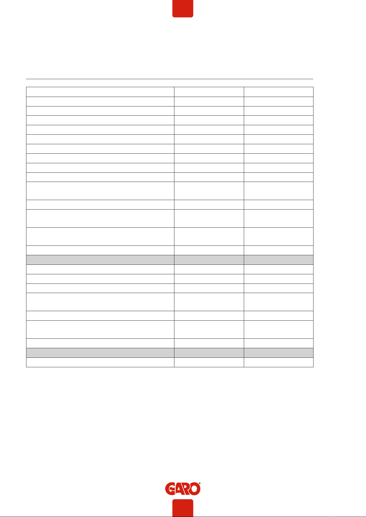
TECHNICAL SPECIFICATIONS
Product type All LS4 models
Standards / Directives IEC 61851-1 and IEC 61439-7
EMC Classification: 2014/30/EU
Installation method: Ground / Wall
Installation environment: Indoor / Outdoor
Location type: Non-restricted Access
Rated Voltage: 230V / 400V 50Hz
Installation systems: TT, TN and IT* systems
Charging type: Mode 3
Charging method AC Charging
Protection class: IP44
Mechanical impact resistance: IK10
Temperature range: -25C - +40C
Weight: 22,5 - 24,5kg depending on model
Standard cable length (fixed cable version): Standard 4m
Rated current withstand 10kA
Rated short-time withstand current 10kA
Rated conditional short-circuit current of an assembly 10kA
Short-circuit protective device type Type C
Rated impulse withstand voltage 4kV
Rated insulation voltage 230/400V
Rated current of each circuit 32A
Rated diversity factor RDF=1
Pollution degree: 3
EMC environmental condition A and B
SERVICE INFORMATION
Care and maintenance GARO charging station LS4
The warranty will only remain valid if service is performed.
Service is performed once a year and must be documented.
General authorization EL is required to perform service, i.e. only a qualified electrical contractor should perform the
service. The service is performed by inspecting the charging station’s exterior and interior parts, manipulating
components and conducting a functional inspection.
If the charging station is connected to a web portal or otherwise controlled from an external system via a service
provider, the service personnel must contact the service provider before a scheduled service. This is to be able to carry
out all steps in the service, but also to avoid automatic error reports being sent from the charging station when service
starts that may lead to other service personnel being called out at great expense. Normally the instructions for the
charging station indicate whether it is connected to a superior service.
If you have questions about service or a need for service, please contact your GARO retailer.
6
EN

FORM FOR ANNUAL SERVICE AND MAINTENENCE
Check point for annual service and maintenence: Status/Value Comment/remark
Visual check outside cabinet
LED indication lit
Check cables, connectors, connector pins
Check sockets
Check color, foil and instructions
Check external antenna (when installed)
Check fastening/fixing to ground/wall
Cean LS4 outside surface
Check locking mechanism
Check both RCCB by pressing “T” button. Check that LED
indication switches to red color for both sides
Function test by GARO test-equipment or similar
Check that electrical power is delivered by indications on test
equipment
Check RFID reader (when available). Indication by 2 or 3
flashes from LED:s
Check Type 2 socket locking function (Type 2 socket versions)
Turn off the electrical power
Check gaskets
Check torque for mains terminals
Check torque for LS4 fixing screws towards ground/wall
Check torque for connectors on contactors, relays,
energymeters and DC-PSU
Check connectors on CCU module
Measure the earthing resistans (Ohm) on EV sockets/cables
with a multimeter
Clean inside when necessary
Turn on the electrical power
Check charging function on both sides
Plant ID: Name: Date:
7
EN

WARRANTY CONDITIONS
1. The product benefits from manufacturer´s warranty. The applicable warranty period must be
stated in purchase documents from your supplier.
2. The product must be installed by a certified installer / contractor.
3. Proper installation, storage and operation conditions must be obtained.
4. Warranties apply only to products installed in their original installation location.
5. Installation, use, care, and maintenance must be normal and in accordance with instructions.
6. Warranty requires a dated, fully filled in Warranty form by an certified installer/contractor. If
the original installation date cannot be verified, then the warranty period begins ninety (90)
days from the date of product manufacture (as indicated by the model and serial number).
7. Warranty does not cover damage occurred by incorrect use of equipment, use of any non-
original spare parts, lack of maintenance or faults caused by disassembly of the product or
unauthorized persons intervention,
8. Warranty does not cover software or update thereof.
9. Warranty does not cover aesthetic deficiencies caused by negligent manipulation or
accidents (breaks or damage to the carcass).
10. Warranty does not cover damage caused by external overvoltage from either grid or car/
charging object.
11. Warranty does not cover damage caused by force major like for example but not limited
to: floods, winds, fires, lightning, accidents, sabotage, military conflicts, terrorism, volcanos,
earthquakes or corrosive environments.
Sverige/Sweden
Garantivillkor enl ALEM 09.
OBS! Fullständigt ifylld garantiblankett krävs.
Garantin gäller ej om produkten varit utsatt för ett isolationstest, sk meggning.
EU Countries (except Sweden)
8
EN

WARRANTY FORM / GARANTIFORMULÄR
LS4 Model: M no:
Electrical installation data
Group fuse (A):
Supply cable dimension:
Function Test
Testbox / EV (model)
Date:
Sign Installer:
Company Name:
Owner / Customer Name:
Installation adress:
9
EN

CU/AL
(picture 1)
(picture 2)
10
EN

(picture 3)
(picture 4)
11
EN

3pcs LS4 connected with TP CAT6 cable to router/switch
5pcs LS4 connected with TP CAT6 cable to router/switch
(picture 5)
(picture 6)
Example of DLM meter installation
Modbus address #2
9600, 8, 1, no parity
Terminals:
#200 - A-
#201 - B+
DLM meter
12
EN

Standard
-KF1
-X12V
-X0V
12V
230V
-KA1 -T1
-QA1
-XN1 -XPE1
-RFID2
-XD2
-QA2
-SW1-RT1 -CC1 -CC2
-RFID1
-XD1
16/32A
16/32A
-FC1 -FB1 -P1
-FC2 -FB2
-Q1 -FC3
-X1
-L1
-L2
-L3
-N
-PE
-P2
-EB1
Q1 =Main breaker 100A
FC3 =Fuse Charge Controller and Powersupply
P1 =Energymeter Left Outlet
P2 =Energymeter Right Outlet
FB1 =RCCB Left Outlet
FB2 =RCCB Right Outlet
FC1 =Fuse Left Outlet
FC2 =Fuse Right Outlet
QA1 =Contactor Left Outlet
QA2 =Contactor Right Outlet
XN1 =N Neutral terminal
XPE1 =PE Terminal Protection Earth
T1 =Powersupply DC
CC1 =Charge Controller (Master)
CC2 =Charge Controller (Slave)
RFID1 =Left Receiver
RFID2 =Right Recevier
KF1 =Led light Topcard
X1 =Incoming terminal
XD1 =Left charging connector
XD2 =Right charging connector
RT1 =4G - Router
SW1 =Ethernet Switch
KA1 =Contactor for Heater Cold Options*
*Cold Option is optional
*RT1 (router) and SW1 (switch) is not
possible in same LS4
13
EN
Other manuals for LS4 Wallmounted
3
This manual suits for next models
1
Table of contents
Other GARO Automobile Accessories manuals
Popular Automobile Accessories manuals by other brands

Whispbar
Whispbar K919W Fitting instructions

JL Audio
JL Audio Stealthbox SB-J-JK2DR/10W1v2 installation guide

dirna Bergstrom
dirna Bergstrom Bycool Green Line Compact 3.0 Mounting instructions

A&E Systems
A&E Systems TRAVEL-AWN 5000 operating instructions

Tritium
Tritium Veefil-RT TRI93.INS.020 installation manual

travall
travall TDG 1688 FITTING INSTRUCTION