GARO TWIN+ User manual

GARO TWIN+
Box 203, SE–335 25 Gnosjö
Phone: +46 (0) 370 33 28 00
garo.se
Manual 380237
Assembly instructions / End User Instruction (EN)
GARO AB
EN

TABLE OF CONTENT
About this manual 3
INFORMATION 3
Warnings 3
Cautions 4
Notes 4
Content 5
INSTALLATION 6
Dimensional sketch 11
USER MANUAL 12
Normal use 12
LED indications 12
Technical specifications 13
Electrical diagram 14
2
EN

INFORMATION
Warnings
About this manual
GARO TWIN+ assortment is a range of EVSE stations for Mode-3
AC charging.
Below are some example of standard features:
• Double outlets or cables for Mode-3 EV charging.
• Up to 2x22kW simultaneous charging from one EVSE
depending on model.
• RCCB and DC-fault monitoring for each side.
• Double mains terminals for easy forwarding of mains cable to
next TWIN+.
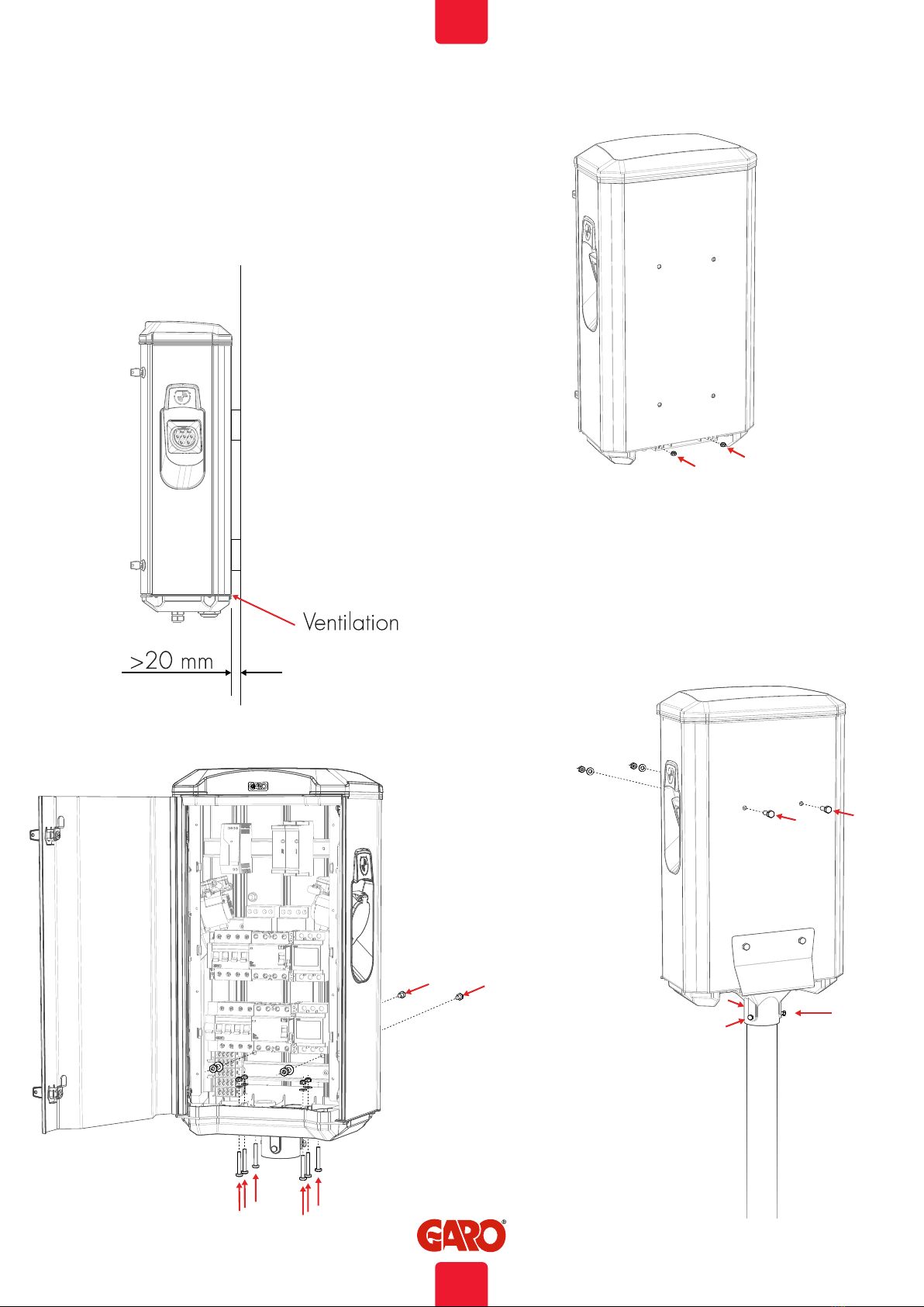
• Suitable for installation on wall or pole.
• LED status indication.
• Upgradeable firmware
• Energy meters for each side
• OCPP via Wifi or LAN
• RFID readers
TWIN+ supports following features
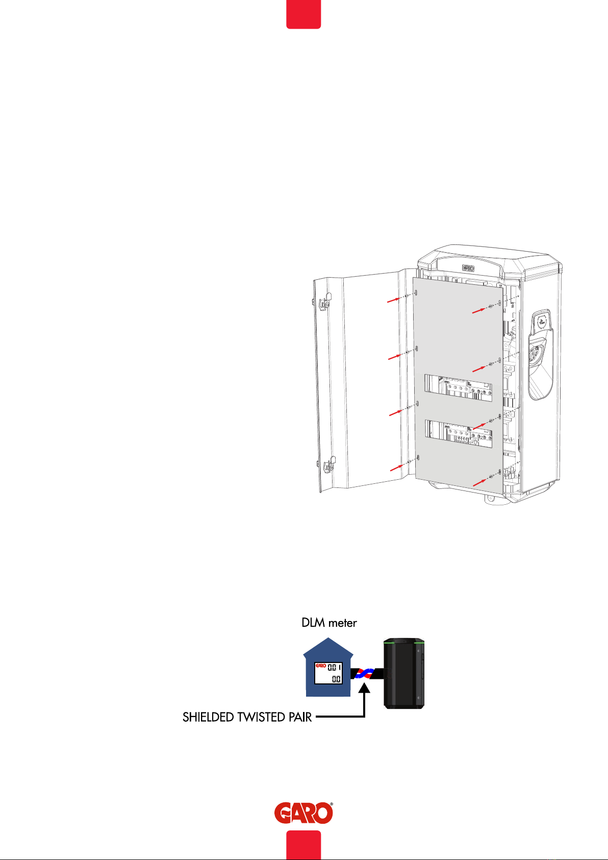
External DLM energy meter
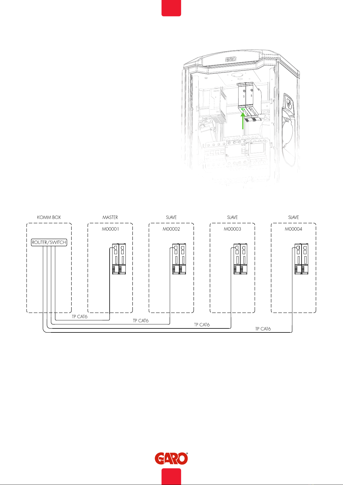
Cluster installation of multiple TWIN+ via Ethernet
Cluster installation of multiple TWIN+, LS4 and GLB+ via Ethernet
Dielectric Voltage Withstand Test is not allowed on
TWIN+
This equipment should not be used by anyone (including
children) with reduced physical, sensory or mental
capacity, or anyone lacking in experience or knowledge,
unless they are provided with supervision or prior
instruction in how to use the equipment by the person
responsible for their safety.
TWIN+ is designed exclusively for charging electric
vehicles.
TWIN+ must be grounded according to local country
installation requirements.
Do not install or use the TWIN+ near flammable,
explosive, harsh, or combustible materials, chemicals, or
vapors.
Turn off the electrical power at the circuit breaker before
installing, configuring, cleaning or maintenance.
Use TWIN+ only within the specified parameters.
Never spray water or any other liquid directly at TWIN+.
Never spray any liquid onto the charge handle or
submerge the charge handle in liquid. Store the charge
handle in the dock to prevent unnecessary exposure to
contamination or moisture.
Do not use this equipment if it appears to be damaged or
if the charging cable appears to be damaged.
Do not modify the equipment installation or any part of the
product.
Do not touch the terminals with fingers or any other
objects.
Do not insert foreign objects into any part of TWIN+
INFORMATION
This document contains general descriptions which are verified to
be accurate at the time of printing. However, because continuous
improvement is a goal at GARO, we reserve the right to make
product and software modifications at any time. This range
is subject to continual product development. Errors, typo and
omissions excepted. Latest manual can always be found at
www.garoemobility.com/support
For full user manual: www.garoemobility.com/support
3
EN

INFORMATION
NotesCautions
Incorrect installation and testing of the TWIN+ could
potentially damage either the vehicle’s battery and/or the
TWIN+ itself.
Do not use private power generators as a power source
for charging.
Do not operate the TWIN+ in temperatures outside its
operating range – see technical specifications.
All installation must be carried out by an authorised
installer and comply with local installation regulations.
If any questions, please contact your local electrical
authority.
Ensure that the charging cable is positioned so it will not
be stepped on, driven over, tripped on, or subjected to
damage or stress.
Unroll the charging cable to prevent it from overheating.
Do not use cleaning solvents to clean any of the
components. The outside of the TWIN+, the charging
cable, and the end of the charging cable should be
periodically wiped with a clean, dry cloth to remove
accumulation of dirt and dust.
Refer to local standards and regulations not to exceed
charging current limitations.
The front cover must always be locked in order to ensure
compliance with IP Code IP44.
Note that 1-phase charging is common in electric vehicles
and L1 and L2 in the TWIN+ is used for this purpose.
Ventilation signal from EV is not supported.
Adapters for charging connectors are not allowed to be
used.
Cord extension sets for charging cable is not allowed to
be used.
4
EN

INFORMATION
GARO TWIN+
Box 203, SE–335 25 Gnosjö
Phone: +46 (0) 370 33 28 00
garo.se
Manual 380237
Installation / Instruktionsmanual
GARO AB
SE
Manual
TWIN+
3X
3X
Keys
Content
5
EN

INSTALLATION
6 Ø 8,5mm (screws not included)
4x M8 L20mm
INSTALLATION
(picture 1)
• Use conductors that are dimensioned in accordance with
local electrical regulations. The selected cable must be able to
sustain periods of constant load of up to 63A.
• The installation must be carried out by an authorized installer.
1. Select suitable group fuse and cable dimension for the
electrical installation. Make sure to consider the cable length
during calculation to avoid risk of voltage drop.
Note: Due to high currents for a long time in the cable, there is a
high risk of voltage drop if the cable is under-dimensioned which
can damage the electronics in an EV.
2. Fill in the fuse and cable information in the Warranty form
located in the installation manual that is included in the box.
3. Mount the TWIN+ on a wall or pole according to picture 1-6.
NOTE! In cases with TWIN+ installed in a grid, Installation order
of the TWIN+ need to follow the order in the attached Master/
slave file. See picture 8
(picture 2)
6
EN

2xM6
2x M8xL20mm + Nut + Washer
3xM6 L12mm
2xM8 L20 + 2xM8 Nut + Washer
6x M6 Nut + Washer
6xM6 L40mm
INSTALLATION
(picture 4)
(picture 5) (picture 6)
Note: Wall installation requires a minimum 20mm distance
between the wall and the TWIN+ to ensure correct cooling, see
picture 3.
When TWIN+ is installed on a pole, the holes at the back side
should be covered/closed by attached screws, see picture 6.
(picture 3)
7
EN

INSTALLATION
6. Install the electrical supply cable to terminals L1-L3, N , PE.
Note: TWIN+ is equipped with double terminals that makes it
easy to forward the supply cable to another TWIN+,
see picture 7.
Phase-rotation is recommended in order to achieve even
load on all phases when several TWIN+ are installed
to same mains.
For example:
1st TWIN+: L1, L2, L3
2nd TWIN+: L3, L1, L2
3rd TWIN+: L2, L3, L1
And so on….
Note: When DLM is pre-configurated from factory, follow
the marked phase order label at incoming terminals. All pre-
configured TWIN+ contains the information about this inside the
cabinet.
Role Serialnumber / M-number
Master M00001
Slave 1 M00002
Slave 2 M00003
Slave 3 M00004
Slave 4 M00005
Slave 5
Slave 6
Slave 7
Slave 8
Slave 9
Slave 10
Master/Slave form
CU/AL MAX16mm2
(picture 7)
(picture 8)
8
EN

INSTALLATION
7. In cases with TWIN+ connected in a grid, install TP cable
CAT6 with RJ45 connectors between each TWIN+ and the
provided ethernet router/switch (located ie. in GARO KOMM
BOX). Se example of ethernet wiring diagram picture 10
Note! Connect the ethernet cable to CC1. The ethernetport on
CC2 is not in use. Se picture 9-10
4pcs TWIN+ in an Ethernet network with Router/Switch
(picture 9)
(picture 10)
9
EN

INSTALLATION
8. In cases with external energy meter (for DLM function), connect
the energy meter communication terminals A- and B+ to TWIN+
Master station terminals 200 A-) and 201 (B+). The energy-
meters modbus adress must be set to #2. The modbus RS-485
communication settings is: Baud 9600, 8bit, 1 stop bit, no parity
9. Fill in the warranty form in the manual.
10. Assembly the protection cover and close the front door. Picture
11
11. Turn on electrical power.
12. Wait a few minutes until the TWIN+ have finished the startup
process and test both sides with a EVSE-tester or an EV. In cases
where authorization (by RFID tag or similar) is needed to start
charging please contact the backend administrator.
13. Doublecheck that the warranty form is completely filled. Sign
with name, date and company in order for the warranty to be
valid.
DLM meter installation
Modbus address #2
9600, 8, 1, no parity
Terminals:
#200 - A-
#201 - B+
(picture 11)
(picture 12)
10
EN

INSTALLATION
660
377
206
Dimensional sketch
11
EN

USER MANUAL
USER MANUAL
Normal use
Connect the charging cable to the EV.
If authorization is activated, please hold a valid RFID-tag against
the RFID reader on the side of the LS4 you want to use or use the
app to authorize charging.
Charging will start instant if the EV is ready for charging. See your
EV charging manual.
When finishing charging, follow the EV’s instructions.
After charging: Release the charging cable from your EV and
place the charging cable at designated place.
LED indications
Felsökning / Support / FAQ mm
www.garoemobility.com/support
3pcs green flash: Waiting for authorization by tag or
App
Constant green flash: Waiting for connection
between EV and TWIN+
EV connected to TWIN+ and charging
TWIN+ waiting for authorization from Backend
Error, reset MCB/RCCB and/or contact your TWIN+
installation partner
RFID-tag not valid
Electrical problem inside TWIN+, check fuses and/or
contact your TWIN+ installation partner
12
EN

USER MANUAL
Technical specifications
Product type All TWIN+ models
Standards / Directives IEC 61851-1 and IEC 61439-7
EMC Classification: 2014/30/EU
Installation method: Ground / Wall
Installation environment: Indoor / Outdoor
Location type: Non-restricted Access
Rated Voltage: 230V / 400V 50Hz
Installation systems: TT, TN and IT* systems
Charging type: Mode 3
Charging method: AC Charging
Protection class: IP44
Mechanical impact resistance: IK10
Temperature range: -25C - +40C
Weight: 14-18kg depending on model
Standard cable length (fixed cable
version):
Standard 4m
Rated current withstand 10kA
Rated short-time withstand current 10kA
Rated conditional short-circuit current
of an assembly
10kA
Short-circuit protective device type Type C
Rated impulse withstand voltage 4kV
Rated insulation voltage 230/400V
Rated current of each circuit 32A
Rated diversity factor RDF=1
Pollution degree: 3
EMC environmental condition A and B
* 1-phase Twin
13
EN

USER MANUAL
-KF1
2DIFR-1DIFR-
1EPX-1NX-
-QA1 -QA2
-FB1
-FB2-FC2
1P-1CF-
-P2
16/32A
16/32A
-XD2-XD1
-X1
L1 N PEL3 L2
FC3
CC2
CC1
T1
AC PLINT
DC PLINT
+
-
Q1 =Main Breaker 100A
P1 =Energymeter Left Outlet
P2 =Energymeter Right Outlet
FB1 =RCCB Left Outlet
FB2 =RCCB Right Outlet
FC1 =Fuse Left Outlet
FC2 =Fuse Right Outlet
FC3 =Fuse Charge Controller and Powersupply
QA1 =Contactor Left Outlet
QA2 =Contactor Right Outlet
XN1 =N Neutral terminal
XPE1 =PE Terminal Protection Earth
CC1 =Charge Controller (Parent)
CC2 =Charge Controller (Child)
RFID1 =Left Receiver
RFID2 =Right Recevier
KF1 =Led light Topcard
X1 =Incoming terminal
XD1 =Left charging connector
XD2 =Right charging connector
Electrical diagram
14
EN

USER MANUAL
L3
L2
L1
N
PE
-X1
1
2
5
3
6
4
7
8
A1
A2
-QA1
12
5
3
6
4
7
8
A1
A2
-QA2
CT2
CT1
CT1
CT2
-XPE1-XN1
CC1
CC2
T1
HÖGER SIDA
VÄNSTER SIDA
123
456
98
NN
-P2
123
456
98
NN
-P1
10A
-FC3
I
2
1
N 6
-FB1
40A
N 51 3
2 4
mA
30
14
13
N 6
-FB2
40A
N 51 3
2 4
mA
30
14
13
I
32A
-FC2
5
6
7
8
1
2
3
4
24
23
I
32A
-FC1
5
6
7
8
1
2
3
4
24
23
AC PLINT
CC1 - Relais 24
CC2 - Relais 24
CC2 - A Mod
CC2 - B-Modbus
CC1 - A Mod
CC1 - B-Modbus
CP
PP
L1
L2
L3
PE
N
-XD1
Red
White CC1-CP
CC1-PP
CP
PP
L1
L2
L3
PE
N
-XD2
CC2-PP
CC2-CP
Red
White
Purple
Purple
Dark Blue
Dark Blue
White
White
Green
Green
KF1/R17
KF1/R18
KF1/R19
KF1/R20
15
EN

USER MANUAL
L1 N
12V DC
230 V
+-
T1
CC1 - Relais 23
CC2 - Relais 23
12V
0V
1
SVART/BLACK 1mm
RÖD/RED 1mm
KF1 0V-
KF1 12V+
CC1 0V
CC2 0V
CC1 12V+
CC2 12V+
1
1
1,5
AC PLINT
FC3
Noll Plint
Jord Plint
16
EN

USER MANUAL
OUT IN
OUT IN
-++-
-++-
CC RFID
12V
+
GND
CT
0V
12V
PE
PE
1A
1B
CP
PP
246 8
5 71 3
Opto1 In-
Opto1 In+
Motor BMotor A
Motor HS1
Relais 13
Motor HS2
Relais 14
GND2 Modbus
B2 Modbus
A2 Modbus
WA
Relais 23
WA
Relais 24
Eth 1
10/100 RJ45
CT
0V
12V
PE
PE
1A
1B
CP
PP
246 8
5 71 3
Opto1 In-
Opto1 In+
Motor BMotor A
Motor HS1
Relais 13
Motor HS2
Relais 14
GND2 Modbus
B2 Modbus
A2 Modbus
WA
Relais 23
WA
Relais 24
Eth 1
10/100 RJ45
Purple
Purple
Dark Blue
Dark Blue
White
White
Green
Green
R17
R18
R19
R20
HEAT
FB1-13
FB1-14
FC1-23
FC1-24
FB2-13
FB2-14
FC2-23
CT1
CT2
P1-8
P1-9
P2-8
DC Plint
AC plint
QA2-A1
DC PLINT
DC PLINT
Klipp dessa två kablar
Cut these two cables
RFID 2
RFID 1
CC1 (LAN)
CC2 (LAN)
Up side
Up side
P2-9
XD1-PP
XD1-CP White/Vit
XD2-CP White/Vit
XD2-PP
Dwon Side
RE/BL
BR/BL
-XD1
GR/BL
YE/BL
RE/BL
BR/BL
-XD2
GR/BL
YE/BL
Down Side
Top Card
-KF1
AC plint
QA1-A1
17
EN

USER MANUAL
155mm
Klipplinje
-FC2
-FC1
-FB1
-FB2
-XD2-XD1
41971
-KF1
-CC1
-CC2
-P1
-P2
-QA2-QA1
155mm
L1-L3,N,PE
-X1
KF1 Top card RGB-Led
CC1 Charge Controller 1
CC2 Charge Controller 2
QA1 Contactor Left Outlet / Connector 1
QA2 Contactor Right Outlet / Connector 2
X1 Incoming terminal
1
FC1 Fuse Left Outlet / Connector 1
FB1 RCCB Left Outlet / Connector 1
P1 Energy Meter Left Outlet / Connector 1
2
FC2 Fuse Right Outlet / Connector 2
FB2 RCCB Right Outlet / Connector 2
P2 Energymeter Right Outlet / Connector 2
18
EN

USER MANUAL
Service / Maintenance
The service must be performed by a professional electrician.
A service form can be found at www.garoemobility.com
In order for the warranty to apply, it is required that a completed
service form/forms, (depending on the age of the product), can
be presented when contacting GARO support or other Garo
support partners.
The most recent service form may not be older than 12 months.
Service is performed by visual inspecting both outside and inside
of theTWIN+, conditioning of components as well as functional
tests. Specific service points can be found in the service form.
If your TWIN+ is connected to Backend Operator or other
external supervised system, GARO recommends that you contact
the operator, to plan the service in advance, in order to avoid
unnecessary errors and warning messages that could lead to
expensive emergency call outs from other service partners. You
can normally find information inside the TWIN+ if it is connected
to a supervised system.
Any questions regarding service, please contact GARO at
YOU WILL NEED FOLLOWING DURING SERVICE:
• Service form + pen
• Key to the front door
• Torx tools and PZ2 screwdriver
• Cleaning cloth
• Test instrument/equipment for EVSE:s, for example GARO
article 352344
19
EN

USER MANUAL
Service and maintenance form
Check point for annual maintenence: Status/ Value Comment/remark
Visual check outside cabinet
LED indication lit
Check cables, connectors, connector pins
Check sockets
Check color, foil and instructions
Check external antenna (when installed)
Check fastening/fixing to ground/wall
Clean TWIN+ outside surface
Check locking mechanism
Check both RCCB by pressing "T" button. Check that LED
indication switches to red color for both sides
Function test by GARO test-equipment or similar
Check that electrical power is delivered by indications on test
equipment
Check RFID reader (when available). Indication by 2 or 3
flashes from LED:s
Check Type 2 socket locking function (Type 2 socket versions)
Turn off the electrical power
Check gaskets
Check torque for mains terminals
Check torque for TWIN+ fixing screws towards ground/wall
Check torque for connectors on contactors, relays,
energymeters and DC-PSU
Check connectors on CCU module
Measure the earthing resistans (Ohm) on EV sockets/cables
with a multimeter
Clean inside when necessary
Turn on the electrical power
Check charging function on both sides
Plant ID: Name: Date:
20
EN
Table of contents
Other GARO Automobile Accessories manuals
Popular Automobile Accessories manuals by other brands

Whispbar
Whispbar K919W Fitting instructions

JL Audio
JL Audio Stealthbox SB-J-JK2DR/10W1v2 installation guide

dirna Bergstrom
dirna Bergstrom Bycool Green Line Compact 3.0 Mounting instructions

A&E Systems
A&E Systems TRAVEL-AWN 5000 operating instructions

Tritium
Tritium Veefil-RT TRI93.INS.020 installation manual

travall
travall TDG 1688 FITTING INSTRUCTION