Gasboy Atlas 9800 User manual

MDE-4652F Atlas® 9800 Electronics Field Installation Instructions · September 2019 Page 1
Introduction
Purpose
This manual provides instructions for installing the Atlas® 9800 Electronics.
Intended Users
This manual is intended for Gasboy®-trained and certified Authorized Service Contractors
(ASCs).
Table of Contents
Topic Page
Introduction 1
Important Safety Information 3
Atlas 9800 Parts 5
Accessing Electronic Components 9
Installing Atlas 9800 Power Supply Assembly (M15579A001) 10
Installing Atlas 9800 CPU Board (M06333KXXXX) 12
Installing Atlas 9800 Pulse-out I/F with EM Totalizer Drive Board (M06587A001) 18
Loading New CPU Software 20
Required Tools
A Phillips® screwdriver is required for installing the Atlas 9800 Electronics.
Parts List
The following table lists the parts required for installing the Atlas 9800 Electronics:
Item # Description Part Number Quantity
1Printed Circuit Assembly (PCA), Central Processing
Unit (CPU) Board
M06333KXXXX 1
2Kit, 115 VAC Power Supply to replace C06397 or
M07588A001
M12421K00X** 1
3Atlas 9800 Power Supply Assembly M15579A001 1
4Kit, 230 VAC Power Supply to replace C06489 or
M07588A003
M12422K00X** 1
MDE-4652F
Atlas® 9800 Electronics Field Installation Instructions
September 2019

Introduction
Page 2 MDE-4652F Atlas® 9800 Electronics Field Installation Instructions · September 2019
Related Documents
Document
Number Title GOLDSM Library
MDE-4255 Gasboy Warranty Policy Statement for USA and Canada • Gasboy Policy Documents
• Gasboy Safety and Warranty Docs
MDE-4334 Commercial and Retail Series Atlas Start-up/Service Manual Gasboy Atlas Pumps/Dispensers
MDE-4363 Atlas Fuel Systems Owner’s Manual Gasboy Atlas Pumps/Dispensers
MDE-4998 Main Display Assembly (M12158A004) for Atlas 9800 Gasboy Atlas Pumps/Dispensers
Abbreviations and Acronyms
Term Description
ASC Authorized Service Contractor
ATC Automatic Temperature Control
CFN Cash Flow Network
CPU Central Processing Unit
DEF Diesel Exhaust Fluid
EEPROM Electronically Erasable Programmable Read Only Memory
EM Electro-mechanical
FMS Fuel Management System
GOLD Gilbarco Online Documentation
J-box Junction Box
LED Light Emitting Diode
NEC National Electric Code
NFPA National Fire Protection Association
OSHA Occupational Safety and Hazard Association
PCA Printed Circuit Assembly
PCU Pump Control Unit
STP Submersible Turbine Pump
Warranty
For warranty information, refer to MDE-4255 Gasboy Warranty Policy Statement for USA and
Canada. For any warranty-related queries, contact Gasboy’s Warranty Department at its
Greensboro location.
5PCA, Serial Electronically Erasable Programmable
Read Only Memory (EEPROM)*
M06656K00X 1
• 9800K Software M06656K001
• 9850 Software M06656K002
• 9840K Software M06656K003
• 9800Q Software M06656K004
• 9840Q Software M06656K005
• 9800 ECAL Software M06656K006
*M06656K100 Kit of the latest versions of all these boards is also available.
**X refers to the required number of displays, where X=1 for 1 display, X=2 for 2 displays,
X=3 for 4 displays.
Item # Description Part Number Quantity

MDE-4652F Atlas® 9800 Electronics Field Installation Instructions · September 2019 Page 3
Important Safety Information
Important Safety Information
Notes: 1) Save this Important Safety Information section
in a readily accessible location.
2) Although DEF is non-flammable, Diesel is
flammable. Therefore, for DEF cabinets that are
attached to Diesel dispensers, follow all the
notes in this section that pertain to flammable
fuels.
This section introduces the hazards and safety precautions
associated with installing, inspecting, maintaining, or servicing
this product. Before performing any task on this product, read
this safety information and the applicable sections in this
manual, where additional hazards and safety precautions for
your task will be found. Fire, explosion, electrical shock, or
pressure release could occur and cause death or serious injury,
if these safe service procedures are not followed.
Preliminary Precautions
You are working in a potentially dangerous environment of
flammable fuels, vapors, and high voltage or pressures. Only
trained or authorized individuals knowledgeable in the related
procedures should install, inspect, maintain, or service this
equipment.
Emergency Total Electrical Shut-Off
The first and most important information you must know is how
to stop all fuel flow to the pump/dispenser and island. Locate
the switch or circuit breakers that shut off all power to all fueling
equipment, dispensing devices, and Submerged Turbine
Pumps (STPs).
Total Electrical Shut-Off Before Access
Any procedure that requires access to electrical components or
the electronics of the dispenser requires total electrical shut off
of that unit. Understand the function and location of this switch
or circuit breaker before inspecting, installing, maintaining, or
servicing Gilbarco equipment.
Evacuating, Barricading, and Shutting Off
Any procedure that requires access to the pump/dispenser or
STPs requires the following actions:
• An evacuation of all unauthorized persons and vehicles
from the work area
• Use of safety tape, cones, or barricades at the affected
unit(s)
Read the Manual
Read, understand, and follow this manual and any other labels
or related materials supplied with this equipment. If you do not
understand a procedure, call a Gilbarco Authorized Service
Contractor or call the Gilbarco Support Center at
1-800-800-7498. It is imperative to your safety and the safety
of others to understand the procedures before beginning work.
Follow the Regulations
Applicable information is available in National Fire Protection
Association (NFPA) 30A; Code for Motor Fuel Dispensing
Facilities and Repair Garages, NFPA 70; National Electrical
Code (NEC), Occupational Safety and Health Administration
(OSHA) regulations and federal, state, and local codes. All
these regulations must be followed. Failure to install, inspect,
maintain, or service this equipment in accordance with these
codes, regulations, and standards may lead to legal citations
with penalties or affect the safe use and operation of the
equipment.
Replacement Parts
Use only genuine Gilbarco replacement parts and retrofit kits
on your pump/dispenser. Using parts other than genuine
Gilbarco replacement parts could create a safety hazard and
violate local regulations.
Federal Communications Commission (FCC) Warning
This equipment has been tested and found to comply with the
limits for a Class A digital device pursuant to Part 15 of the FCC
Rules. These limits are designed to provide reasonable
protection against harmful interference when the equipment is
operated in a commercial environment. This equipment
generates, uses, and can radiate radio frequency energy, and if
not installed and used in accordance with the instruction manual,
may cause harmful interference to radio communications.
Operation of this equipment in a residential area is likely to cause
harmful interference in which case the user will be required to
correct the interference at his own expense. Changes or
modifications not expressly approved by the manufacturer could
void the user’s authority to operate this equipment.
Safety Symbols and Warning Words
This section provides important information about warning
symbols and boxes.
Alert Symbol
This safety alert symbol is used in this manual and on
warning labels to alert you to a precaution which must be
followed to prevent potential personal safety hazards. Obey
safety directives that follow this symbol to avoid possible injury
or death.
Signal Words
These signal words used in this manual and on warning labels
tell you the seriousness of particular safety hazards. The
precautions below must be followed to prevent death, injury, or
damage to the equipment:
DANGER: Alerts you to a hazard or unsafe practice
which will result in death or serious injury.
WARNING: Alerts you to a hazard or unsafe practice
that could result in death or serious injury.
CAUTION with Alert symbol: Designates a hazard or
unsafe practice which may result in minor injury.
CAUTION without Alert symbol: Designates a hazard or
unsafe practice which may result in property or
equipment damage.
Working With Fuels and Electrical Energy
Prevent Explosions and Fires
Fuels and their vapors will explode or burn, if ignited. Spilled or
leaking fuels cause vapors. Even filling customer tanks will
cause potentially dangerous vapors in the vicinity of the
dispenser or island.
DEF is non-flammable. Therefore, explosion and fire safety
warnings do not apply to DEF lines.
The EMERGENCY STOP, ALL STOP, and
PUMP STOP buttons at the cashier’s station
WILL NOT shut off electrical power to the
pump/dispenser. This means that even if you
activate these stops, fuel may continue to flow
uncontrolled.
You must use the TOTAL ELECTRICAL
SHUT-OFF in the case of an emergency and not
the console’s ALL STOP and PUMP STOP or
similar keys.
!
WARNING
!
!
!
!
Important Safety Information
Page 4 MDE-4652F Atlas® 9800 Electronics Field Installation Instructions · September 2019
No Open Fire
Open flames from matches, lighters, welding torches or
other sources can ignite fuels and their vapors.
No Sparks - No Smoking
Sparks from starting vehicles, starting or using power
tools, burning cigarettes, cigars or pipes can also ignite fuels and
their vapors. Static electricity, including an electrostatic charge on
your body, can cause a spark sufficient to ignite fuel vapors.
Every time you get out of a vehicle, touch the metal of your
vehicle, to discharge any electrostatic charge before you
approach the dispenser island.
Working Alone
It is highly recommended that someone who is capable of
rendering first aid be present during servicing. Familiarize
yourself with Cardiopulmonary Resuscitation (CPR) methods, if
you work with or around high voltages. This information is
available from the American Red Cross. Always advise the
station personnel about where you will be working, and caution
them not to activate power while you are working on the
equipment. Use the OSHA Lockout/Tagout procedures. If you
are not familiar with this requirement, refer to this information in
the service manual and OSHA documentation.
Working With Electricity Safely
Ensure that you use safe and established practices in working
with electrical devices. Poorly wired devices may cause a fire,
explosion or electrical shock. Ensure that grounding connections
are properly made. Take care that sealing devices and
compounds are in place. Ensure that you do not pinch wires
when replacing covers. Follow OSHA Lockout/Tagout
requirements. Station employees and service contractors need to
understand and comply with this program completely to ensure
safety while the equipment is down.
Hazardous Materials
Some materials present inside electronic enclosures may
present a health hazard if not handled correctly. Ensure that you
clean hands after handling equipment. Do not place any
equipment in the mouth.
In an Emergency
Inform Emergency Personnel
Compile the following information and inform emergency
personnel:
• Location of accident (for example, address, front/back of
building, and so on)
• Nature of accident (for example, possible heart attack, run
over by car, burns, and so on)
• Age of victim (for example, baby, teenager, middle-age,
elderly)
• Whether or not victim has received first aid (for example,
stopped bleeding by pressure, and so on)
• Whether or not a victim has vomited (for example, if
swallowed or inhaled something, and so on).
IMPORTANT: Oxygen may be needed at scene if gasoline has
been ingested or inhaled. Seek medical advice immediately.
Lockout/Tagout
Lockout/Tagout covers servicing and maintenance of machines
and equipment in which the unexpected energization or start-up
of the machine(s) or equipment or release of stored energy could
cause injury to employees or personnel. Lockout/Tagout applies
to all mechanical, hydraulic, chemical, or other energy, but does
not cover electrical hazards. Subpart S of 29 CFR Part 1910 -
Electrical Hazards, 29 CFR Part 1910.333 contains
specific Lockout/Tagout provision for electrical hazards.
The pump/dispenser contains a chemical known to the State
of California to cause cancer.
WARNING
!
The pump/dispenser contains a chemical known to the State
of California to cause birth defects or other reproductive
harm.
WARNING
!
Gilbarco Veeder-Root encourages the recycling of our
products. Some products contain electronics, batteries,
or other materials that may require special
management practices depending on your location.
Please refer to your local, state, or country regulations
for these requirements.
Gasoline/DEF ingested may cause unconsciousness
and burns to internal organs. Do not induce vomiting.
Keep airway open.
Oxygen may be needed at scene. Seek medical
advice immediately.
DEF generates ammonia gas at higher temperatures. When
opening enclosed panels, allow the unit to air out to avoid
breathing vapors.
If respiratory difficulties develop, move victim away from source
of exposure and into fresh air. If symptoms persist, seek medical
attention.
WARNING
!
WARNING
!
Gasoline inhaled may cause unconsciousness and
burns to lips, mouth and lungs.
Keep airway open.
Seek medical advice immediately.
WARNING
!
Gasoline/DEF spilled in eyes may cause burns to eye
tissue.
Irrigate eyes with water for approximately
15 minutes.
Seek medical advice immediately.
WARNING
!
Gasoline/DEF spilled on skin may cause burns.
Wash area thoroughly with clear water.
Seek medical advice immediately.
WARNING
!
DEF is mildly corrosive. Avoid contact with eyes, skin, and
clothing. Ensure that eyewash stations and safety showers are
close to the work location. Seek medical advice/recommended
treatment if DEF spills into eyes.
WARNING
!
MDE-4652F Atlas® 9800 Electronics Field Installation Instructions · September 2019 Page 5
Atlas 9800 Parts
Atlas 9800 Parts
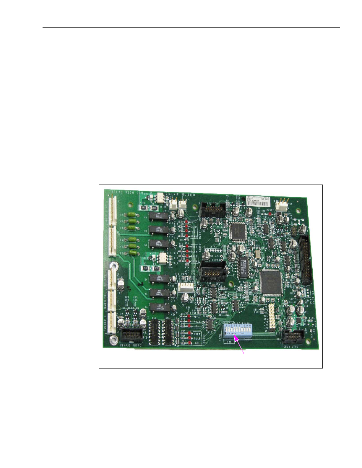
Atlas 9800 CPU Board (M06333KXXXX)
Features of the Atlas 9800 CPU board are as follows:
• Accepts either 115 or 230 VAC on AUTH line inputs.
• Compatible with all RS-485 I/F Boards (C06389, M05248A001, M06725A001).
• Compatible with all Pulse-out I/F Boards (C06425, C06746, M05158A001,
M05158A002, M05158A003, M06587A001).
• Replaces 9800 CPU Boards (C06391, C06392, C06393, C06394, C06500, C06501,
C06502, C06503, M05346A001, M05346A002, M05346A003, M05346A004).
• Requires new Power Supply M15579A001 (refer to “Atlas 9800 Power Supply Assembly
(M15579A001)” on page 6).
• Requires Automatic Temperature Control (ATC) Kit (M08218K001) for models
(9850A/Q, 9850K, 9852A/Q, 9853A/Q, and 9840A/Q) where ATC is present.
Figure 1: Atlas 9800 CPU Board
The ON position (Closed) of the switch is
towards the center of the board.
Atlas 9800 Parts
Page 6 MDE-4652F Atlas® 9800 Electronics Field Installation Instructions · September 2019
The following table lists the CPU boards with corresponding software type and pump type:
Note: The following software types can be loaded on any one of the CPU boards by using the
appropriate Serial EEPROM Board (M06656K00X).
CPU Boards Software Type Pump Type
M06333K9800K 9800K 9852K, 9853K
M06333K9850 9850 9850A*, 9850Q, 9850K
M06333K9840K 9840K 9840K
M06333K9800AQ 9800Q 9852A/Q, 9853A/Q, 9822A/Q, 9823A/Q/K
M06333K9840AQ 9840Q 9840A, 9840Q
M06333KECAL 9800K 9862KX, 9872KX
*If the serial number is lower than 472238, use the M06333K9800AQ CPU
Board or appropriate EEPROM board.
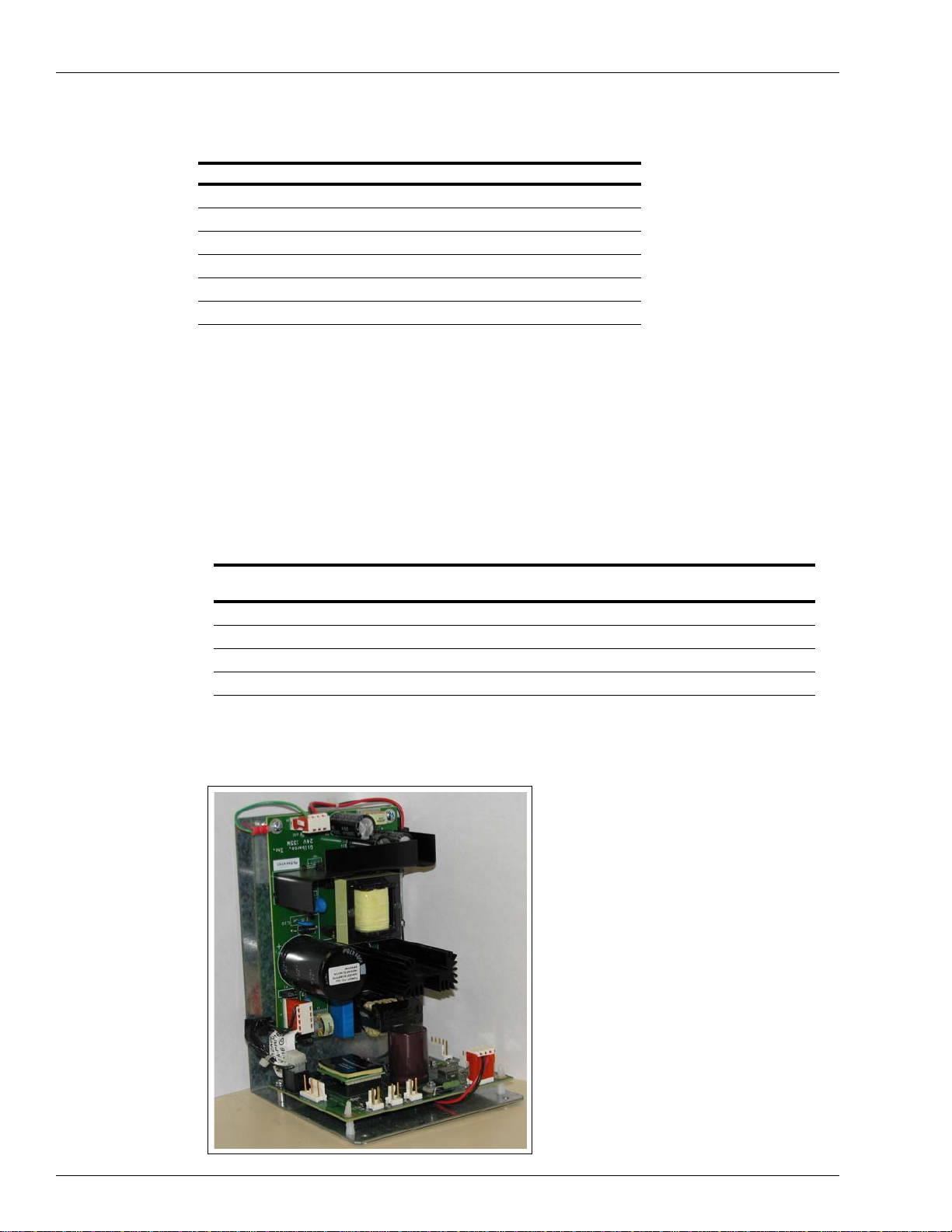
Atlas 9800 Power Supply Assembly (M15579A001)
Features of the Atlas 9800 power supply are as follows:
• Required for M06333 CPU Boards (refer Figure 1 on page 5).
• Compatible with the following 9800 CPU Boards: C06391, C06392, C06393, C06394,
C06500, C06501, C06502, C06503, M05346A001, M05346A002, M05346A003,
M05346A004, and M06333KXXXX.
• Required for Atlas PRIME.
• Replaces current power supplies (9800) as shown in the following table:
Description Old Power Supply Part Number
Replacement Power Supply
Part Number
Kit to replace 115 VAC PS with Battery C06397, M07588A001 M12421K00X*
115 VAC PS without Battery C06396, M07588A002 M15579A001
Kit to replace 230 VAC PS with Battery C06489, M07588A003 M12422K00X*
230 VAC PS without Battery C06488, M07588A004 M15579A001
*X refers to the required number of displays, where X=1 for 1 display, X=2 for 2 displays, X=3 for 4 displays.
Figure 2: Atlas 9800 Power Supply Assembly

MDE-4652F Atlas® 9800 Electronics Field Installation Instructions · September 2019 Page 7
Atlas 9800 Parts
Atlas 9800 Serial EEPROM Board (M06656K00X)
Features of the Atlas 9800 Serial EEPROM board are as follows:
• Used to reprogram the software on the new Atlas 9800 CPU board (refer Figure 1 on
page 5
Serial EEPROM
Board Software Type Pump Type
M06656K001* 9800K 9852K, 9853K
M06656K002* 9850 9850A, 9850Q, 9850K
M06656K003* 9840K 9840K
M06656K004* 9800Q 9852A/Q, 9853A/Q,
9822A/Q, 9823A/Q/K
M06656K005* 9840Q 9840A, 9840Q
M06656K006* 9800K 9862KX, 9872KX
*M06656K100 Kit of the latest versions of all of these
boards is also available.
).
• Provides Light Emitting Diode (LED) indicators to monitor software transfer.
Figure 3: LED Indicators
LEDs for Indication

Atlas 9800 Parts
Page 8 MDE-4652F Atlas® 9800 Electronics Field Installation Instructions · September 2019
Atlas 9800 Pulse-out I/F Board with EM Totalizer Drive (M06587A001)
Features of the Atlas 9800 Pulse-out I/F board with Electro-mechanical (EM) Totalizer Drive
are as follows:
• Provides up to two dual channel outputs per hose.
• Compatible with 9800 CPU Boards (C06391, C06392, C06393, C06394, C06500,
C06501, C06502, C06503, M05346A001, M05346A002, M05346A003, M05346A004,
and M06333KXXXX).
• Can be used in place of existing 9800 dual channel Pulse-out I/F Boards (C06746,
M05158A002).
• Can be used in place of existing 9800 dual Pulse-out I/F Boards (C06425, M05158A001).
• Can be used in place of existing 9800 I/F Board (M05158A003).
Figure 4: Atlas 9800 Pulse-out I/F Board with EM Totalizer Drive
MDE-4652F Atlas® 9800 Electronics Field Installation Instructions · September 2019 Page 9
Accessing Electronic Components
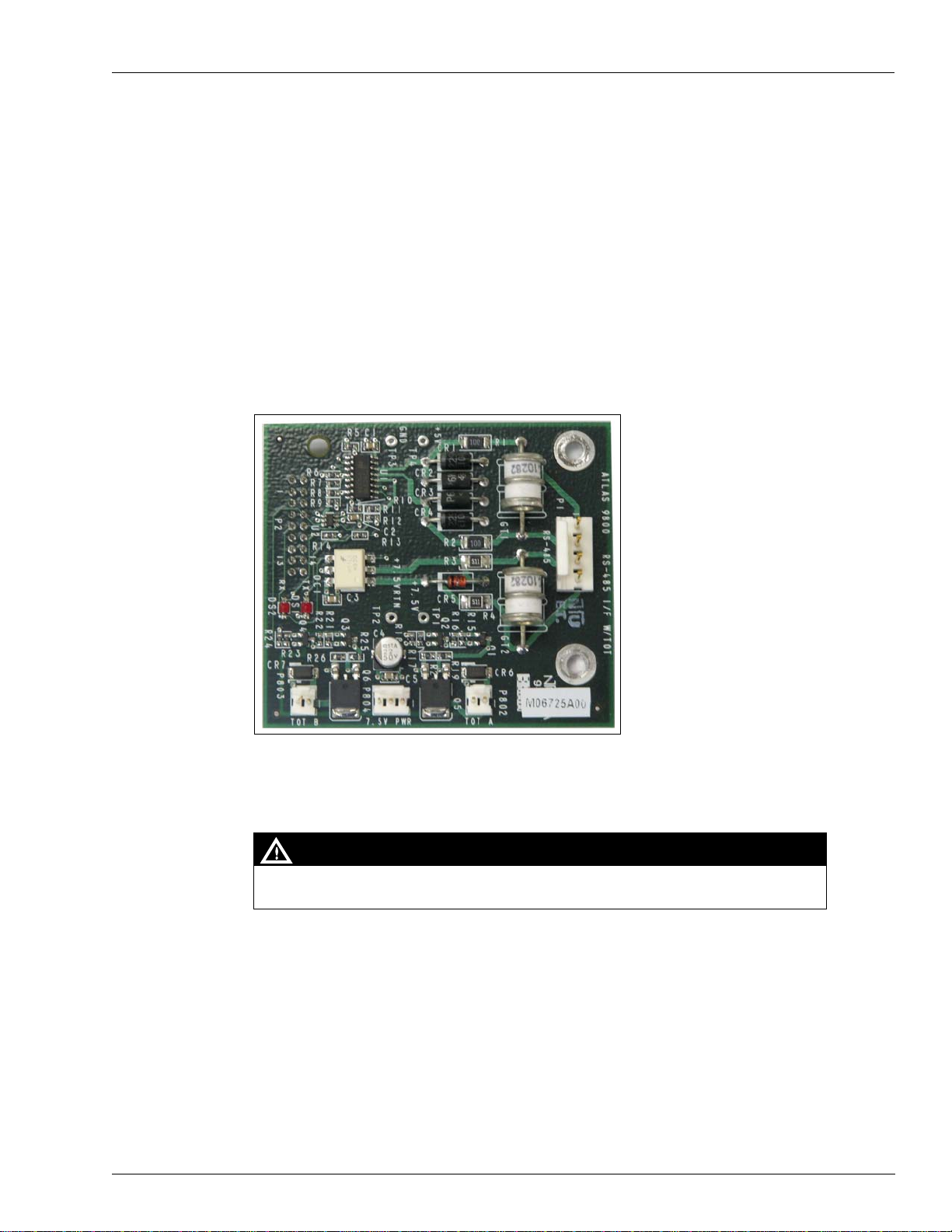
K-Pump RS-485 with Totalizer (M06725A001)
The features of K-Pump RS-485 with Totalizer board are as follows:
• Allows RS-485 communications between 9800 and a Cash Flow Network (CFN) PLUS
System, TopKAT™ PLUS Electronic System or Atlas PRIME.
• Compatible with 9852K, 9853K, 9850K, 9840K, 9852A/Q, 9853A/Q, 9840A/Q,
9822A/Q, 9823A/Q/K, 9862KX, 9872KX.
• Compatible with 9800 CPU Boards (C06391, C06392, C06393, C06394, C06500,
C06501, C06502, C06503, M05346A001, M05346A002, M05346A003, M05346A004,
M06333KXXXX).
• Can be used in place of previous 9800 RS-485 I/F Board C06389 and M05248A001.
• Required for Atlas PRIME.
Figure 5: K-Pump RS-485 with Totalizer
Accessing Electronic Components
Always remove AC power from the pump/dispenser before servicing the unit. Failure to
turn off the unit before servicing may result in serious injury or death.
WARNING
To access the electronic components, proceed as follows:
1Unlock and remove the front panel on the pump/dispenser.
2Remove the two bolts/screws located over the tabs of the bezel assembly. Lift the bezel
assembly upwards and out to remove.
Note: For A and Q models with front load nozzle, remove the nozzle boot plastic shroud
(two screws) before removing the bezel assembly.
3Loosen the two screws that secure the display panel, remove them if required, and pivot the
display panel down.
Installing Atlas 9800 Power Supply Assembly (M15579A001)
Page 10 MDE-4652F Atlas® 9800 Electronics Field Installation Instructions · September 2019
Installing Atlas 9800 Power Supply Assembly
(M15579A001)
If the existing power supply is a working M07588A00X or M15579A001 assembly, proceed
to “Installing Atlas 9800 CPU Board (M06333KXXXX)” on page 12.
To install the Atlas 9800 power supply, proceed as follows:
Always remove AC power from the pump/dispenser before servicing the unit. Failure to
turn off the unit before servicing may result in serious injury or death.
WARNING
1Check the existing power supply. If the existing supply is not a M07588A00X or
M15579A001, or if it is not working, it must be replaced. For the correct replacement part
number, refer to “Atlas 9800 Power Supply Assembly (M15579A001)” on page 6.
2Ensure to disconnect AC power to the pump/dispenser.
3Disconnect the AC power cable from the P3 connector. Disconnect the DC cables from the P2
and P1 connectors.
4Unscrew and remove all the screws that hold the power supply. Retain the screws for installing
the new power supply.
5Remove the power supply. For models with plastic standoffs, after the screws are removed,
carefully unsnap the power supply from the standoffs and remove it. Remove any standoffs
that may have remained on the power supply and place them back into the plate where the
power supply was mounted.(See Figure 6 on page 11)

MDE-4652F Atlas® 9800 Electronics Field Installation Instructions · September 2019 Page 11
Installing Atlas 9800 Power Supply Assembly (M15579A001)
Figure 6: Power Supply
M15579A001 Assembly
replaces obsolete single
board power supplies
Obsolete single board power
supply shown for reference
6Install the new power supply on the standoffs. Ensure that the P1 connector is closest to the
CPU board and P3 connector is away from the CPU. If the pump model is 9822 or 9823, the
P1 connector is closest to the pump-handle assembly.
7Reinstall the screws removed in step 4 on page 10. For models with plastic standoffs, carefully
push the power supply onto the plastic standoffs before installing the screws.
8Reconnect the following:
• Cables and AC power to the P3 connector.
• Display backlight to the P2 connector.
• CPU DC to the P1 connector.

Installing Atlas 9800 CPU Board (M06333KXXXX)
Page 12 MDE-4652F Atlas® 9800 Electronics Field Installation Instructions · September 2019
Installing Atlas 9800 CPU Board (M06333KXXXX)
To install the Atlas 9800 CPU board, proceed as follows:
Always remove AC power from the pump/dispenser before servicing the unit. Failure to
turn off the unit before servicing may result in serious injury or death.
WARNING
1Check the existing power supply. If the existing supply is not a M07588A00X or
M15579A001 assembly, it must be replaced. For details, refer to “Installing Atlas 9800 Power
Supply Assembly (M15579A001)” on page 10.
2Ensure that the AC power to the pump/dispenser is disconnected. Remove the DC cable from
the P1 connector on the power supply.
3If the pump/dispenser does not have ATC installed, proceed to step 4. If the pump/dispenser
model is one of the following - 9850A/Q, 9850K, 9852A/Q, 9853A/Q, 9840A/Q, the ATC
support bracket (that holds the ATC black box) must be replaced. Use the M08218K001 Kit to
install the new bracket.
4If the pump/dispenser has a RS-485 or pulse-out I/F board, remove the screws that secure the
I/F board and disconnect it from the existing CPU board.
5Disconnect all cables going to the connectors on the CPU board. Ensure that you note the
connectors and cables so that they can be reconnected to the correct connector.
6Unscrew and remove all the screws securing the CPU board. Retain the screws for installing
the new CPU board.
7Remove the CPU board. For models with plastic standoffs, carefully unsnap the CPU board
from the standoffs and remove it. Remove any standoffs that may have remained on the CPU
board and place them back into the plate where the board was mounted.
8The new CPU Board (M06333KXXXX) can be configured for various operating conditions
using the jumpers JP1 to JP9. Check these jumpers and change, if required. Jumper settings
must be changed with the power to the pump/dispenser “Off”. CPU board only reads new
jumper settings during power up.
JP1 - Baud Rate
This jumper selects the baud rate for the RS-485 communications.
Baud Rate JP1
1200 Jumpered
9600 Open

MDE-4652F Atlas® 9800 Electronics Field Installation Instructions · September 2019 Page 13
Installing Atlas 9800 CPU Board (M06333KXXXX)
JP2 - Mode
This jumper selects the mode in which the pump/dispenser operates. Set the mode to “Online”
if the pump/dispenser communicates to a controlling system (for example, Gasboy TopKAT
PLUS or CFN PLUS System). Set the mode to “Standalone” for all other configurations [for
example, Gasboy Series 1000 Fuel Management System (FMS) or no controlling system].
Mode JP2
Standalone Jumpered
Online Open
JP3, JP4 - Leak Detect Delay
These jumpers select the delay time used by leak detectors in Submersible Turbine Pump
(STP) applications. The delay time is the period between the activation of the submersible
pump and the activation of the slow flow valve. The delay time must be set according to the
type of leak detector installed on the STP to allow for a normal leak test for each transaction.
The delay time must be set to 0 seconds for suction pumps.
Delay Time JP3 JP4
0 seconds Jumpered Jumpered
4 seconds Jumpered Open
5 seconds Open Jumpered
6 seconds Open Open
JP5 - Hose Pressurization
For US Gallons (always in Hose Pressurization mode), this jumper is ignored. This jumper is
used to determine if hose pressurization is used. If enabled, the slow flow valve is opened
before reset is complete, to allow the hose to be pressurized before fuel dispensing begins.
Pressurization JP5
Enabled Jumpered
Disabled Open
JP6 - Authorization
This jumper allows activation or non-activation of the pump/dispenser from an external source
(for example, an FMS). When jumpered, a 115/230 VAC signal must be present on the Control
Feed/authorization line (refer to the wiring diagram for your model pump/dispenser) for pump
activation to occur (required setting for Gasboy Series 1000). When open, the Control Feed
line signal is ignored (required setting for Standalone mode).
Authorization JP6
Enabled Jumpered
Disabled Open
Note: For JP6 Authorization, in Standalone mode, the authorization signal must be present to
activate the pump.

Installing Atlas 9800 CPU Board (M06333KXXXX)
Page 14 MDE-4652F Atlas® 9800 Electronics Field Installation Instructions · September 2019
JP7 - Electronic Totalizers
This jumper must be open for normal operation (electronic totals protected). When jumpered,
this allows the electronic totals to be reset.
Totalizers JP7
Reset Jumpered
Normal Open
JP8 - Pump Disable Detection
This jumper allows the pump/dispenser to detect or ignore a pump disable (RS-485 break
character). When detection is enabled, the pump/dispenser will monitor the RS-485
communications for a pump disable signal. When received, any transaction in progress will be
halted and then completed. This setting must only be used when the pump/dispenser is
communicating to a Gasboy CFN System. This setting must be disabled (jumpered) for all
other configurations (for example, Gasboy TopKAT or Standalone).
Detection JP8
Disabled Jumpered
Enabled Open
JP9
This jumper is spare and not in use.
9CPU Board (M06333KXXXX) can also be configured for various operating conditions using
the switch positions SW2-1 through SW2-10. Check these switches and change, if required.
Switch settings must be changed with the power to the pump/dispenser “Off”. CPU board only
reads new switch settings during power up.
Note: A switch in the closed position indicates that the switch is “On” (towards the center of
the CPU board).
SW2-1 through SW2-4
These four switches serve a dual purpose: as an address setting when communicating through
RS-485 I/F (for example, Gasboy CFN systems), or as a pulser output rate selector when in
Pulse-out I/F configuration (for example, Gasboy Series 1000 FMS).
Address Switches (if JP2 is Open)
A unique address identifier must be set when the pump/dispenser is communicating through
RS-485 I/F. The unique address must correspond to the address of a unique Pump Control Unit
(PCU) configured in a Gasboy CFN or TopKAT system. There are 16 possible address
combinations and up to 16 pumps (single or twin) can be connected through the RS-485 I/F.
Addressing must start at 1 and continue sequentially through 16. The physical wiring order
does not have to correspond with the address order; that is, the first pump/dispenser on the
RS-485 does not have to be address 1.
Address SW2-1 SW2-2 SW2-3 SW2-4
1Closed Closed Closed Closed
2Open Closed Closed Closed
3Closed Open Closed Closed

MDE-4652F Atlas® 9800 Electronics Field Installation Instructions · September 2019 Page 15
Installing Atlas 9800 CPU Board (M06333KXXXX)
Pulse Output Rate Switches (if JP2 is Jumpered)
When the pump/dispenser is connected to an external controlling equipment that requires
pulse output signals (for example, Gasboy Series 1000), the pulse signals are sent through the
pulse-out I/F board. Setting Switches SW2-1 through SW2-3 configures the Pulse-out rate
required by the monitoring equipment. Pulse-out rate represents the pulses per unit (gallon,
liter, or imperial gallon).
Pulse Rate SW2-1 SW2-2 SW2-3
1:1 Closed Closed Closed
10:1 Open Closed Closed
100:1 Closed Open Closed
250:1 Open Open Closed
500:1 Closed Closed Open
None Open Closed Open
None Closed Open Open
None Open Open Open
Maximum pulse output rate that can be achieved depends on the model of the pump/dispenser
and the unit of measure. Pulse output rate of 1000:1 is not supported when using the CPU
board.
Note: 9800 refers to models 9852, 9853, 9822, and 9823.
Unit of Measure 9800 Models 9840A/Q Models 9840K Models 9850 Models
US Gallons 500:1 500:1 500:1 100:1
Liters 100:1 100:1 10:1 10:1
Imperial Gallons 500:1 500:1 500:1 100:1
Note: If a valid pulse-out rate is not selected, the CPU will not output pulses.
4Open Open Closed Closed
5Closed Closed Open Closed
6Open Closed Open Closed
7Closed Open Open Closed
8Open Open Open Closed
9Closed Closed Closed Open
10 Open Closed Closed Open
11 Closed Open Closed Open
12 Open Open Closed Open
13 Closed Closed Open Open
14 Open Closed Open Open
15 Closed Open Open Open
16 Open Open Open Open
Address SW2-1 SW2-2 SW2-3 SW2-4

Installing Atlas 9800 CPU Board (M06333KXXXX)
Page 16 MDE-4652F Atlas® 9800 Electronics Field Installation Instructions · September 2019
Leading zeros are always suppressed in the tens and hundreds place to the left of the decimal
point. In Standalone mode, positions to the right of the decimal point are displayed based on
the pulse output rate and unit of measure selected.
Pulse Rate Gallons - US or Imperial Liters and/or 9850
1:1 XXX XXXX
10:1 XXX.X XXXX.X
100:1 XXX.XX XXXX.XX
250:1 XXX.XXX XXXX.XX
500:1 XXX.XXX XXXX.XX
Timeout Switch (if JP2 is Jumpered)
When the pump/dispenser is in the Standalone mode, including Pulse-out I/F configurations, it
will turn off an active hose outlet if it does not detect input pulses for 4 minutes and 15
seconds.
Timeout SW2-4
Enabled Closed
Disabled Open
SW2-5 and SW2-6 - Unit of Measure Selection
These two switches set the unit of measure (US gallons, liters, or Imperial gallons) that the
pump/dispenser will use to meter fuel.
Unit of Measure SW2-5 SW2-6
US Gallons Closed Closed
Liters Open Closed
Imperial Gallons Closed Open
NOT USED (default US Gallons) Open Open
SW2-7 - EM Totalizer Enable
This switch is only used on K model pumps/dispensers (excluding the 9850K model). When
closed (“On”), it enables the pump/dispenser to drive electro-mechanical totalizers used on
some K models pump. On A and Q models, this switch must be set to disabled (open).
EM Totalizer SW2-7
Enabled Closed
Disabled Open
SW2-8 - BDM Enable
This switch must be open for normal operation.
SW2-9 - Software Load Enable
This switch must be open for normal operation. When this switch is closed, it enables loading
the new software (refer to “Loading New CPU Software” on page 20).
SW2-10
This switch is not used (or close it to ground input).

MDE-4652F Atlas® 9800 Electronics Field Installation Instructions · September 2019 Page 17
Installing Atlas 9800 CPU Board (M06333KXXXX)
10 Set the new CPU board on the standoffs. Reinstall the screws removed in step 6 on page 12.
For models with plastic standoffs, ensure that the metal standoffs are under the mounting holes
located between P2 and P3, and the outside corner next to P5. Carefully push the new CPU
board onto the standoffs before installing the screws.
11 Reconnect all the cables (P1 to P9, and P11), if applicable. Reconnect the DC cable to P1 of
the power supply.
12 Apply power to the pump/dispenser and note the display(s). The first set of numbers displayed
will be the software version (for example, 06013), the second set is the software type (for
example, 9800 1), and the third set is the firmware version (for example, 01008).
Ensure that the displayed software type is correct for the pump/dispenser model that the CPU
is installed in (refer to the following table). If it is, proceed to step 13. If not, proceed to
“Loading New CPU Software” on page 20.
Displayed Software Type Corresponding Pump/Dispenser Model
“9800 1” Corresponds to the 9800Q Software:
9852A/Q, 9853A/Q, 9822A/Q, 9823A/Q/K
“9800 2” Corresponds to the 9800K Software:
9852K, 9853K, 9862KX, 9872KX
“9800 3”* Corresponds to the 9800K Software:
9862KX*, 9872KX*
“9840 1” Corresponds to the 9840Q Software:
9840A, 9840Q
“9840 2” Corresponds to the 9840K Software:
9840K
“9850” Corresponds to all 9850 Software:
9850A, 9850Q, 9850K
*Note: Version 06.0.20 or later.
13 Reassemble the pump/dispenser by proceeding to “Accessing Electronic Components” on
page 9 and follow the steps in reverse order.

Installing Atlas 9800 Pulse-out I/F with EM Totalizer Drive Board (M06587A001)
Page 18 MDE-4652F Atlas® 9800 Electronics Field Installation Instructions · September 2019
Installing Atlas 9800 Pulse-out I/F with EM Totalizer Drive
Board (M06587A001)
JP1, JP2, and JP3
This board assembly can be configured for use in one of the following pump/dispenser
configurations:
• Dual Channel, Single Hose Pulse-out I/F (refer Figure 7 on page 19)
• Single Channel, Dual/Single Hose Pulse-out I/F (refer Figure 8 on page 19)
• Dual Channel, Dual Hose Pulse-out I/F (refer Figure 9 on page 19)
The following table shows the jumper settings and wires to connect to in the Junction Box (J-
box), based on the configuration.
Check JP1 - JP3 jumpers and change them, if required. The jumper settings must be changed
only when the power to the pump/dispenser is removed, to protect the circuit that they are
connected to.
Default configuration is Single Channel, Dual/Single Hose Pulse-out I/F. When configured for
Dual Channel, Single Hose Pulse-out I/F, or Single Channel, Dual/Single Hose Pulse-out I/F,
the P3 Connector is not connected.
When configured for Dual Channel, Dual Hose Pulse-out I/F, the P3 connector is used.
Jumper Settings
Single Channel, Dual/Single
Hose Pulse-out I/F
(Default Setting)
Dual Channel, Single Hose
Pulse-out I/F
Dual Channel, Dual Hose
Pulse-out I/F
Wire Color JP1 Position 1
JP2 Position 1
JP3 Open
JP1 Position 2
JP2 Position 2
JP3 Open
JP1 Position 2
JP2 Position 2
JP3 Jumpered
Red Pulse out Side 1 Pulse out Side1A Pulse out Side 1A
Green Pulse out Side 2 Pulse out Side1B Pulse out Side 1B
White Common Return Side 1A Return Side 1A Return
Black No Connection Side 1B Return Side 1B Return
Brown No Connection No Connection Pulse out Side 2A
Orange No Connection No Connection Pulse out Side 2B
Yell ow No Connection No Connection Side 2A Return
Gray No Connection No Connection Side 2B Return
JP4 and JP5
When this board is used in a model A or Q pump/dispenser or 9850K, jumpers JP4 and JP5 are
set to the Q/A position. When this board is used for all other K models except 9850K, these
jumpers must be in the K position.

MDE-4652F Atlas® 9800 Electronics Field Installation Instructions · September 2019 Page 19
Installing Atlas 9800 Pulse-out I/F with EM Totalizer Drive Board (M06587A001)
Configurations
Figure 7: Dual Channel, Single Hose Pulse-out I/F
Pulse Side 1
Side 1B Output
Side 1A Output
Side 1A Return
Side 1A Return
Figure 8: Single Channel, Dual/Single Hose Pulse-out I/F
Pulse Side 1
Pulse Side 2
Side 1 Output
Side 2 Output
Common Return
Figure 9: Dual Channel, Dual Hose Pulse-out I/F
Pulse Side 1
Side 1A Output
Side 1B Output
Side 1A Return
Side 1B Return
Pulse Side 2
Side 2A Output
Side 2B Output
Side 2A Return
Side 2B Return

Loading New CPU Software
Page 20 MDE-4652F Atlas® 9800 Electronics Field Installation Instructions · September 2019
Loading New CPU Software
CPU board is configured and programmed before shipping from the factory. In the event the
software must be changed, proceed as follows:
Always remove AC power from the pump/dispenser before servicing the unit. Failure to
turn off the unit before servicing may result in serious injury or death.
WARNING
1Disconnect AC power to the pump/dispenser. Remove the DC cable from the P1 connector on
the power supply.
2Set switch SW2-9 to the closed (“ON”) position.
3Select the appropriate Atlas 9800 Serial EEPROM board for the software type you want to
load (refer to “Atlas 9800 Serial EEPROM Board (M06656K00X)” on page 7).
4Ensure that JP1 is not jumpered on the Serial EEPROM board assembly. Carefully insert into
the P14 connector located in the middle of the CPU board.
5Connect the DC cable to the P1 connector on the power supply. Connect AC power to the
pump/dispenser.
6At this point, on the Serial EEPROM board assembly, the green “PWR” and yellow “BUSY”
LEDs will illuminate. A few seconds later, the yellow “BUSY” LED will go off and the green
“OK” LED will illuminate, indicating that the download is successful. Ensure that the green
“OK” LED illuminates before proceeding. If the red “NOT OK” LED illuminates, repeat steps
1 to 6. If the red “NOT OK” LED illuminates after a second attempt, call your service
representative or contact Gasboy Technical Service.
7Disconnect AC power to the pump/dispenser. Remove the DC cable from the P1 connector on
the power supply.
8Set Switch SW2-9 to the open position.
Note: If SW2-9 is left in the closed position, the unit will not display the software version,
software type, and firmware version during power up.
9Carefully remove the Serial EEPROM board assembly from the P14 connector.
10 Connect the DC cable to the P1 connector on the power supply.
11 Connect AC power to the pump/dispenser.
Table of contents
Other Gasboy Dispenser manuals


Popular Dispenser manuals by other brands


Mityvac
Mityvac MV6412 user manual

Atlas Copco
Atlas Copco SDS Product instructions

Franke
Franke SD80 Installation and operating instructions

Vestergaard
Vestergaard LifeStraw manual

Hirschmann
Hirschmann Ceramus HF instruction manual

Tuthill
Tuthill Fill-Rite Owners installation, operation, and safety manual