Gasboy Atlas 9100 series User manual

MDE-4809 Atlas™ 9100 Series Totalizer Retrofit Kit (M05813K004) Installation Instructions · May 2009 Page 1
Introduction
Purpose This manual provides instructions to install the Lower Front Totalizer Retrofit Kit for Atlas™
9100 Series Units (M05813K004).
Note: A new Bezel with a totalizer opening may be required when installing the kit. Use
templates to identify the correct Bezel.
Table of Contents
Topic Page
Introduction 1
Important Safety Information 3
Installation of the Lower Totalizer Retrofit Kit 5
Required Tools
The following tools are required for the installation of the kit:
• Phillips®Screwdriver
•Wrench
•HammerandPunch
Parts List The following table lists the parts included in this kit.
Item Description Part Number Quantity
1Face Dial Blank Totalizer 025548 1
2Nut Hex Keps W/EXT LW 6 Q12068-02 10
3SCR SLF V/R 510500-325 S00702 1
4Modified Gear Plate Assy 015891 1
5Totalizer 8 WH VR 370016 S65336 1
6SCR V/R 510500-327 S00704 2
7Totalizer Seal V/R 28698K S00207 2
8INSTR-9100 Series Front T 032933 1
98 X 10 X 4 200#C.K. R.S. 018072 1
10 CRTN 25-3/4X9-3/4X6-1/8 R 018116 1
MDE-4809
Atlas™9100 Series Totalizer Retrofit Kit
(M05813K004) Installation Instructions
May 2009

Introduction
Page 2 MDE-4809 Atlas™ 9100 Series Totalizer Retrofit Kit (M05813K004) Installation Instructions · May 2009
Warranty
For information on warranty, refer to MDE-4255 Gasboy’s Warranty Policy Statement. If you
have any warranty-related questions, contact Gasboy’s Warranty Department at its Greensboro
location.

MDE-4809 Atlas™ 9100 Series Totalizer Retrofit Kit (M05813K004) Installation Instructions · May 2009 Page 3
Important Safety Information
Important Safety Information
This section introduces the hazards and safety precautions
associated with installing, inspecting, maintaining or servicing
this product. Before performing any task on this product, read
this safety information and the applicable sections in this
manual, where additional hazards and safety precautions for
your task will be found. Fire, explosion, electrical shock or
pressure release could occur and cause death or serious
injury, if these safe service procedures are not followed.
Preliminary Precautions
You are working in a potentially dangerous environment of
flammable fuels, vapors, and high voltage or pressures. Only
trained or authorized individuals knowledgeable in the related
procedures should install, inspect, maintain or service this
equipment.
Emergency Total Electrical Shut-Off
The first and most important information you must know is
how to stop all fuel flow to the pump/dispenser and island.
Locate the switch or circuit breakers that shut off all power to
all fueling equipment, dispensing devices, and Submerged
Turbine Pumps (STPs).
Total Electrical Shut-Off Before Access
Any procedure that requires access to electrical components
or the electronics of the dispenser requires total electrical
shut off of that unit. Understand the function and location of
this switch or circuit breaker before inspecting, installing,
maintaining, or servicing Gasboy equipment.
Evacuating, Barricading and Shutting Off
Any procedure that requires access to the pump/dispenser or
STPs requires the following actions:
• An evacuation of all unauthorized persons and vehicles
from the work area
• Use of safety tape, cones or barricades at the affected
unit (s)
• A total electrical shut-off of the affected unit (s)
Read the Manual
Read, understand and follow this manual and any other
labels or related materials supplied with this equipment. If you
do not understand a procedure, call a Gasboy Authorized
Service Contractor or call the Gasboy Service Center at 1-
800-444-5529. It is imperative to your safety and the safety of
others to understand the procedures before beginning work.
Follow the Regulations
Applicable information is available in National Fire Protection
Association (NFPA) 30A; Code for Motor Fuel Dispensing
Facilities and Repair Garages, NFPA 70; National Electrical
Code (NEC), Occupational Safety and Hazard Association
(OSHA) regulations and federal, state, and local codes. All
these regulations must be followed. Failure to install, inspect,
maintain or service this equipment in accordance with these
codes, regulations and standards may lead to legal citations
with penalties or affect the safe use and operation of the
equipment.
Replacement Parts
Use only genuine Gasboy replacement parts and retrofit kits
on your pump/dispenser. Using parts other than genuine
Gasboy replacement parts could create a safety hazard and
violate local regulations.
Safety Symbols and Warning Words
This section provides important information about warning
symbols and boxes.
Alert Symbol
This safety alert symbol is used in this manual and
on warning labels to alert you to a precaution which must be
followed to prevent potential personal safety hazards. Obey
safety directives that follow this symbol to avoid possible
injury or death.
Signal Words
These signal words used in this manual and on warning
labels tell you the seriousness of particular safety hazards.
The precautions below must be followed to prevent death,
injury or damage to the equipment:
DANGER:Alerts you to a hazard or unsafe practice
which will result in death or serious injury.
WARNING: Alerts you to a hazard or unsafe practice
that could result in death or serious injury.
CAUTION with Alert symbol: Designates a hazard or
unsafe practice which may result in minor injury.
CAUTION without Alert symbol: Designates a hazard
or unsafe practice which may result in property or
equipment damage.
Working With Fuels and Electrical Energy
Prevent Explosions and Fires
Fuels and their vapors will explode or burn, if ignited. Spilled
or leaking fuels cause vapors. Even filling customer tanks will
cause potentially dangerous vapors in the vicinity of the
dispenser or island.
The EMERGENCY STOP, ALL STOP, and
PUMP STOP buttons at the cashier’s station
WILL NOT shut off electrical power to the pump/
dispenser. This means that even if you activate
these stops, fuel may continue to flow
uncontrolled.
You must use the TOTAL ELECTRICAL SHUT-
OFF in the case of an emergency and not the
console’s ALL STOP and PUMP STOP or
similar keys.
!
WARNING
!
!
!
!

Important Safety Information
Page 4 MDE-4809 Atlas™ 9100 Series Totalizer Retrofit Kit (M05813K004) Installation Instructions · May 2009
No Open Fire
Open flames from matches, lighters, welding
torches or other sources can ignite fuels and their vapors.
No Sparks - No Smoking
Sparks from starting vehicles, starting or using power tools,
burning cigarettes, cigars or pipes can also ignite fuels and
their vapors. Static electricity, including an electrostatic
charge on your body, can cause a spark sufficient to ignite
fuel vapors. Every time you get out of a vehicle, touch the
metal of your vehicle, to discharge any electrostatic charge
before you approach the dispenser island.
Working Alone
It is highly recommended that someone who is capable of
rendering first aid be present during servicing. Familiarize
yourself with Cardiopulmonary Resuscitation (CPR) methods,
if you work with or around high voltages. This information is
available from the American Red Cross. Always advise the
station personnel about where you will be working, and
caution them not to activate power while you are working on
the equipment. Use the OSHA Lockout/ Tagout procedures. If
you are not familiar with this requirement, refer to this
information in the service manual and OSHA documentation.
Working With Electricity Safely
Ensure that you use safe and established practices in
working with electrical devices. Poorly wired devices may
cause a fire, explosion or electrical shock. Ensure that
grounding connections are properly made. Take care that
sealing devices and compounds are in place. Ensure that you
do not pinch wires when replacing covers. Follow OSHA
Lockout/Tagout requirements. Station employees and service
contractors need to understand and comply with this program
completely to ensure safety while the equipment is down.
Hazardous Materials
Some materials present inside electronic enclosures may
present a health hazard if not handled correctly. Ensure that
you clean hands after handling equipment. Do not place any
equipment in the mouth.
In an Emergency
Inform Emergency Personnel
Compile the following information and inform emergency
personnel:
• Location of accident (for example, address, front/back of
building, and so on)
• Nature of accident (for example, possible heart attack, run
over by car, burns, and so on)
• Age of victim (for example, baby, teenager, middle-age,
elderly)
• Whether or not victim has received first aid (for example,
stopped bleeding by pressure, and so on)
• Whether or not a victim has vomited (for example, if
swallowed or inhaled something, and so on)
IMPORTANT: Oxygen may be needed at scene if gasoline
has been ingested or inhaled. Seek medical advice
immediately.
Lockout/Tagout
Lockout/Tagout covers servicing and maintenance of
machines and equipment in which the unexpected
energization or start-up of the machine(s) or equipment or
release of stored energy could cause injury to employees or
personnel. Lockout/Tagout applies to all mechanical,
hydraulic, chemical or other energy, but does not cover
electrical hazards. Subpart S of 29 CFR Part 1910 - Electrical
Hazards, 29 CFR Part 1910.333 contains specific Lockout/
Tagout provision for electrical hazards.
The pump/dispenser contains a chemical known to the
State of California to cause cancer.
WARNING
!
The pump/dispenser contains a chemical known to the
State of California to cause birth defects or other
reproductive harm.
WARNING
!
Gasoline ingested may cause unconsciousness
and burns to internal organs.
Do not induce vomiting.
Keep airway open.
Oxygen may be needed at scene.
Seek medical advice immediately.
WARNING
!
Gasoline inhaled may cause unconsciousness
and burns to lips, mouth and lungs.
Keep airway open.
Seek medical advice immediately.
WARNING
!
Gasoline spilled in eyes may cause burns to eye
tissue.
Irrigate eyes with water for approximately 15
minutes.
Seek medical advice immediately.
!
WARNING
!
Gasoline spilled on skin may cause burns.
Wash area thoroughly with clear water.
Seek medical advice immediately.
WARNING
!
MDE-4809 Atlas™ 9100 Series Totalizer Retrofit Kit (M05813K004) Installation Instructions · May 2009 Page 5
Installation of the Lower Totalizer Retrofit Kit
Installation of the Lower Totalizer Retrofit Kit
Read all important warnings and safety information prior to working on units.
IMPORTANT INFORMATION
To install the Lower Front Totalizer Retrofit Kit for Atlas 9100 Series Units (M05813K004),
proceed as follows:
1Remove the existing dial face. Retain the screws for later use.
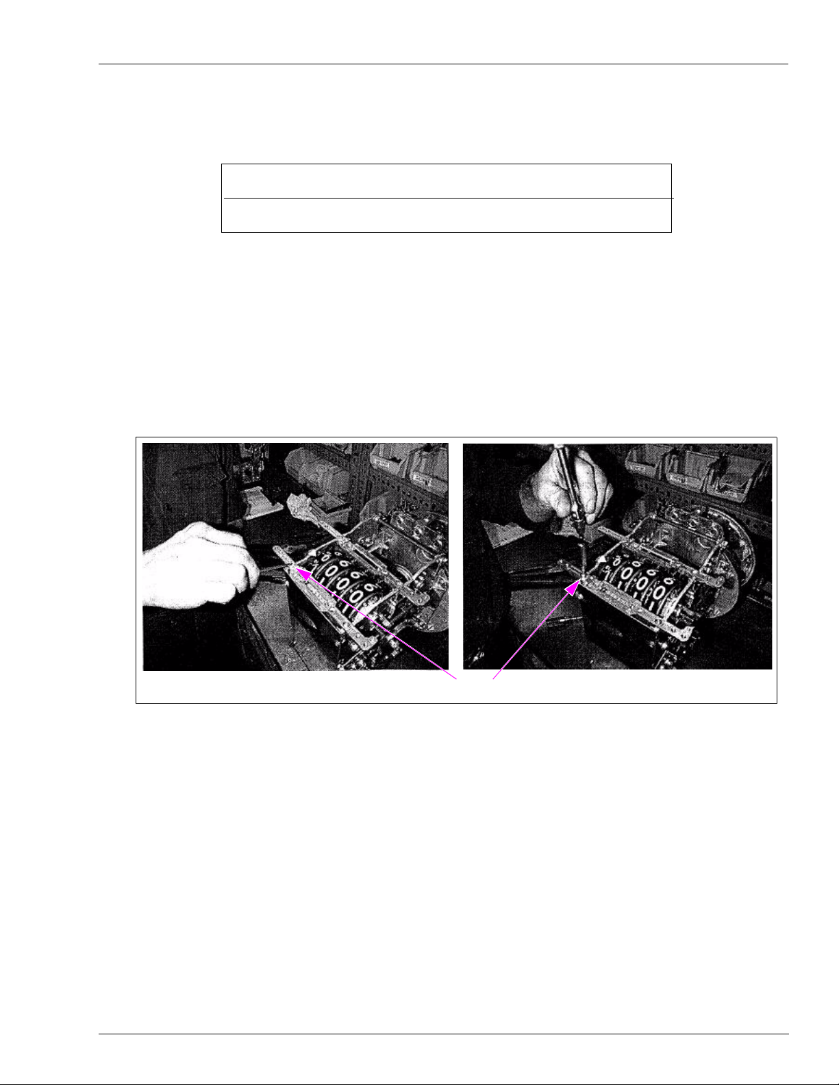
2Remove seal caps from the existing upper rear totalizer, using a hammer and punch.
Figure 1: Removing Seal Caps from the Totalizer
(i) (ii)
Seal Cap
Installation of the Lower Totalizer Retrofit Kit
Page 6 MDE-4809 Atlas™ 9100 Series Totalizer Retrofit Kit (M05813K004) Installation Instructions · May 2009
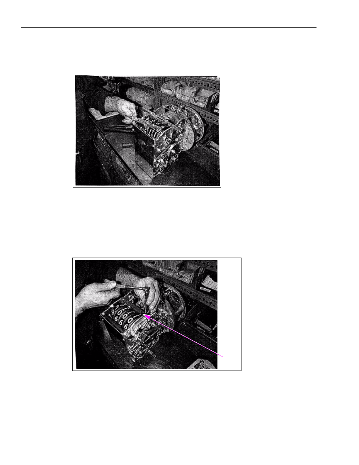
3Remove the two screws that secure the totalizer, using a wrench.
Figure 2: Removing the Screws
4Remove the totalizer from the register assembly.
5On the opposite or the front side of the non-computer, remove the two screws and bracket
from the lower totalizer position.
Figure 3: Removing the Bracket
Bracket

MDE-4809 Atlas™ 9100 Series Totalizer Retrofit Kit (M05813K004) Installation Instructions · May 2009 Page 7
Installation of the Lower Totalizer Retrofit Kit
6Install the slotted gear plate, using the bolt provided in the kit.
Note: Hold the gear plate while tightening the bolt to ensure that the gearing turns smoothly.
Figure 4: Installing the Slotted Gear Plate
(i) (ii)
Slotted Gear Plate Bolt
7Install the front totalizer to the lower totalizer position.
Figure 5: Installing the Front Totalizer
Front Totalizer

Atlas™ is a trademark of Gasboy International. Phillips®is a registered trademark of The Phillips Screw Co.
© 2009 GASBOY
7300 West Friendly Avenue · Post Office Box 22087
Greensboro, North Carolina 27420
Phone 1-800-444-5529 · http://www.gasboy.com · Printed in the U.S.A.
MDE-4809 Atlas™ 9100 Series Totalizer Retrofit Kit (M05813K004) Installation Instructions · May 2009
8Fasten the front totalizer to the register assembly, using two screws.
Figure 6: Installing the Front Totalizer
9Install new seal caps on the totalizer screws to prevent tampering with the totalizer.
Figure 7: Installing New Seal Caps
Totalizer
New Seal Cap
10 Install the new dial face, using the screws removed in step 1.
This completes the installation of the Lower Front Totalizer Retrofit Kit for Atlas 9100 Series
Units.
Other Gasboy Dispenser manuals


Popular Dispenser manuals by other brands


Technical Concepts
Technical Concepts OneShot Plus installation instructions

Franke
Franke XINX625 Installation and operating instructions

Steris
Steris Basil 3600 installation instructions

Cornelius
Cornelius VIPER Service manual

Asymtek
Asymtek Century C-721 Series Operation manual

Bunn
Bunn JDF-2S Service & repair manual