Gasboy 9800A Series User manual

SERIES 9800A
PUMPS AND DISPENSERS
DIAGNOSTIC MANUAL
C35797
REV. 03/07/03
Copyright 2003 by Gasboy International LLC All rights reserved.
The information in this document is confidential and proprietary. No further disclosure shall be made without
permission of Gasboy International LLC. Gasboy International LLC believes that the information in this document is
accurate and reliable. However, we assume no responsibility for its use, nor for any infringements of patents or other
rights of third parties resulting from its use. We reserve the right to make changes at any time without notice.
GASBOY INTERNATIONAL LLC LANSDALE, PA

035282 Rev. 1267
GASBOY INTERNATIONAL LLC
707 North Valley Forge Rd. Lansdale, PA, 19446 ●(215) 855-4631 ●FAX: (215) 855-0341
IMPORTANT WARNINGS AND SAFEGUARDS
Gasoline and petroleum products are flammable. To avoid injury or death to persons or damage to equipment or
property, follow these listed warnings and other warnings and precautions outlined in this manual when installing, using,
or working around this equipment. Check with GASBOY Technical Services for compatibility of liquids with pump
materials.
TURN OFF AND LOCK OUT ALL POWER TO PUMP BEFORE PERFORMING SERVICE, MAINTENANCE OR IN THE EVENT
OF A FUEL SPILL.
All products must be installed by a
qualified installer and used in
conformance with all building, fire, and
environmental codes and other safety
requirements applicable to its
installation and use, including, but not
limited to, NFPA 30, NFPA 30A, NFPA
395 & NFPA 70. A qualified installer is
familiar with fuel systems installations
under the above stated building, fire,
and environmental codes and other
safety requirements for the particular
type of installation.
This product is only part of a fuel
dispensing system and additional
equipment and accessories, such as,
but not limited to, breakaway
connectors, shear valves, pressure
regulators, flow limiters, and other
safety devices may be necessary to
meet the applicable codes.
For maximum safety, we recommend
that all employees be trained as to the
location and procedure for turning off
power to the entire system. Instructions
regarding proper operation of the
equipment along with the appropriate
safety warnings should be posted in
plain view at the fuel island.
Before performing service or
maintenance (including changing of fuel
filters or strainers) or in the event of a
fuel spill, turn off and lock out all power
to the system. In battery-powered
pumps, disconnect power source. In
submersible pump applications, turn off
and lock out power at the master panel
and close any impact valves to the
submersible pump and any other
dispensers which use that submersible
pump. AC power can feed back into a
shut-off dispenser when dispensers
share a common submersible pump or
starter relay. Also block islands so no
vehicles can pull up to the dispenser
when the dispenser is being worked on.
DO NOT use Teflon tape for any pipe
threads in the product.
DO NOT use consumer pumps for
pumping fuel or additives into aircraft.
DO NOT use commercial pumps for
direct fueling of aircraft without filters
and separators necessary to ensure
product purity.
DO NOT use where sanitary design is
required (for food products for human
consumption) or with water-based
liquids.
DO NOT smoke near the pump or when
using the pump.
DO NOT use near open flame or
electrical equipment which may ignite
fumes.
DO NOT permit the dispensing of
gasoline or other petroleum products
into a vehicle with its motor running.
DO NOT permit the dispensing of
gasoline or other petroleum products
into unapproved containers or into
approved containers in or on vehicles
including trucks. All containers must be
filled on the ground to prevent static
discharge. Always use Approved and
Listed hoses and nozzles with electric
pumps and dispensers.
DO NOT block open the nozzle in any
manner. Nozzles shall conform to UL
and NFPA code requirements for
attended or unattended service.
DO ensure that the pump is equipped
with proper filters based on the product
being dispensed and its intended use.
DO wear safety goggles and protective
clothes when dispensing any liquid
which may be potentially harmful or
hazardous.
DO keep all parts of body and loose
clothing clear of belts, pulleys, and other
exposed moving parts at all times.
DO require washing and changing of
clothes if fuel is spilled on a person or
his/her clothing. Keep away from open
flames, sparks, or people smoking.
DO provide a receptacle for catching
product from pump/meter when
servicing.
DO clean up product spills on the
driveway. Turn off and lock out all
power prior to cleanup.
DO insure pump is properly grounded.
DO insure hose is compatible with fluid
being dispensed.
DO inspect hose, nozzle, and pump on
a regular basis for wear, damage, or
other conditions which may create a
safety or environmental hazard.
DO make sure all pipe threads are
properly cut and the inside reamed to
remove burrs. Use UL classified
gasoline-resisting compound on all
joints of gasoline handling piping.
Sealing compound must also be
resistant to Gasohol (Ethanol and
Methanol). Use gasoline-resistant pipe
compound on male threads only; pipe
compound used on female threads can
be squeezed into the supply line where
it can enter the product stream and
become lodged in the pump or meter.
DO ensure that junction box covers are
in place and properly tightened. Mating
surfaces between the box and cover
must be free of dirt, nicks, and
scratches. All unused entries into the
junction box must be properly plugged.

03/07/03 Contents-1
CONTENTS
Section 1: INTRODUCTION
About this Book......................................................................................... 1-1
Using the Troubleshooting Section........................................................... 1-1
Section 2: CHASSIS WIRING
Junction Boxes.......................................................................................... 2-1
AC Junction Box .................................................................................. 2-1
DC Junction Box.................................................................................. 2-1
115VAC/60 Cycle Pump Wiring................................................................ 2-3
115VAC/60 Cycle Dispenser Wiring......................................................... 2-4
230VAC/50 Cycle Pump Wiring................................................................ 2-5
230VAC/50 Cycle Dispenser Wiring......................................................... 2-6
115VAC/60 Cycle Front Load Option Pump Wiring.................................. 2-7
115VAC/60 Cycle Front Load Option Dispenser Wiring........................... 2-8
230VAC/50 Cycle Front Load Option Pump Wiring.................................. 2-9
230VAC/50 Cycle Front Load Option Dispenser Wiring........................... 2-10
Section 3: ELECTRONIC HEAD ASSEMBLY
Overall Layout........................................................................................... 3-1
CPU PCB.................................................................................................. 3-2
Connectors........................................................................................... 3-3
Jumpers............................................................................................... 3-5
LED Indicators ..................................................................................... 3-6
Test Points........................................................................................... 3-6
SW Switches........................................................................................ 3-6
Address Switches ................................................................................ 3-8
Pulser Output Rate Switches............................................................... 3-8
LCD Display PCB (C01373)...................................................................... 3-9
Connector ............................................................................................ 3-9
Jumpers............................................................................................... 3-10
Sale Backlight PCB (C06372)................................................................... 3-11
Connector ............................................................................................ 3-11
RS-485 Interface PCB (C06389) ............................................................. 3-12
Connectors........................................................................................... 3-12
LED Indicators ..................................................................................... 3-13
Pump Interface PCB (06425).................................................................... 3-14
Connectors........................................................................................... 3-15
LED Indicators ..................................................................................... 3-15
Power Supply PBC ................................................................................... 3-16
Connectors........................................................................................... 3-17
LED Indicators ..................................................................................... 3-17
Test Points........................................................................................... 3-17
Pump Relays............................................................................................. 3-18
Connectors........................................................................................... 3-19
Ballast Assembly....................................................................................... 3-20
Connectors........................................................................................... 3-20
Fluorescent Lamp Assembly (C06398), Fluorescent Lamp (033412)...... 3-21
Connector ............................................................................................ 3-21

GASBOY Series 9800A
Contents-2 03/07/03
Heater/Thermostat Cable Assembly......................................................... 3-22
Connector ............................................................................................ 3-22
Power Bracket Assembly (C06436).......................................................... 3-23
Connectors........................................................................................... 3-23
Section 4: TROUBLESHOOTING
Using This Section.................................................................................... 4-1
Section 5: REPLACEMENT INSTRUCTIONS
General Information .................................................................................. 5-1
Electronic Component Access.................................................................. 5-2
Replacing the Platform Assembly............................................................. 5-3
Replacing the CPU PCB........................................................................... 5-5
Replacing the LCD Display PCB............................................................... 5-6
Replacing the Sale Backlight PCB............................................................ 5-7
Replacing the Power Supply PCB ............................................................ 5-8
Replacing the RS-485 or Pump I/F PCB .................................................. 5-9
Replacing the Ballast Cable Assembly..................................................... 5-10
Replacing the Heater Cable Assembly..................................................... 5-13
Appendix: PARTS LIST
Using This Parts List................................................................................. 1
9800A Single Assembly – Front View....................................................... 2
9800A Single Assembly –Side View......................................................... 4
9800A Twin Assembly –Front View.......................................................... 6
9800A Twin Assembly –Side View ........................................................... 8
9840A Assembly – Front View.................................................................. 10
9840A Assembly –Side View.................................................................... 12
9840A Chassis.......................................................................................... 14
9840AX Chassis........................................................................................ 16
9850AS Chassis........................................................................................ 18
9850AXS Chassis..................................................................................... 20
9850AXTW1 Chassis................................................................................ 22
9850AXTW2 Chassis................................................................................ 24
9852A, 9853A Chassis ............................................................................. 26
9853AHC Chassis..................................................................................... 28
9852AX, 9853AX Chassis......................................................................... 30
9852ATW1 Chassis Assembly.................................................................. 32
9853ATW1M Chassis Assembly............................................................... 34
9852AXTW1, 9853XTW1 Chassis Assembly........................................... 36
9852ATW2, 9853ATW2 Chassis Assembly ............................................. 38
9852AXTW2, 9853AXTW2 Chassis Assembly......................................... 40
Assembly Breakdowns
Air Separator Assembly ............................................................................ 42
Barrier, Intrinsically Safe (IS), Front Load Nozzle Option......................... 43
Check Valves............................................................................................ 44
9800A Single Dial Enclosure .................................................................... 45
9800A Twin Dial Enclosure....................................................................... 46
9840A, 9840AX Dial Enclosure................................................................. 47
Flange Assembly....................................................................................... 48
Motor Mount.............................................................................................. 48

Contents
0069 Contents-3
Support Assembly..................................................................................... 48
Float Assembly.......................................................................................... 49
Float Assembly Breakdown ...................................................................... 50
High Hose Retriever Parts........................................................................ 51
Internal Retriever Breakdown ................................................................... 52
9840A Manifold Assembly ....................................................................... 53
9840AX Manifold Assembly...................................................................... 53
9853AHC Pump Discharge....................................................................... 54
9853AHC Manifold.................................................................................... 54
9853ATW1M Manifold Assembly.............................................................. 55
9800AXTW1 Manifold Assembly .............................................................. 55
Mechanical Totalizer................................................................................. 56
9850A, 9850AX, 9850AXTW Meter Assembly ......................................... 57
Liquid Controls Meter Cover Assembly Breakdown (9850A) .................. 58
Liquid Controls Meter Housing Assembly Breakdown (9850A)............... 60
9840A, 9852A,9853A, 9853AHC, 9852ATW1, 9852ATW2, 9853ATW2,
9853ATW1M Meter Assembly............................................................. 62
9852AXTW1, 9853AXTW1, 9840AX Meter Assembly ............................. 63
9852AXTW2, 9853AXTW2 Meter Assembly ............................................ 64
9800A Meter Assembly Breakdown.......................................................... 66
9840A Motor.............................................................................................. 68
9850A Motor.............................................................................................. 69
9852A, 9853A Motor................................................................................. 70
9853AHC Motor ........................................................................................ 71
9852ATW1 Motor...................................................................................... 72
9852TW2, 9853ATW2, 9853ATW1M Motor............................................. 73
9853ATW2, 9853ATW1M Motor, 380V .................................................... 74
Nozzle Boot, Front Load Option................................................................ 75
9840 Pumping Unit Assembly................................................................... 76
9850A Pump and Platform Assembly....................................................... 77
9852A, 9853A Pumping Unit Assembly.................................................... 78
9853AHC Pumping Unit Assembly........................................................... 79
9852ATW1 Pumping Unit Assembly......................................................... 80
9853ATW1M Pumping Unit Assembly...................................................... 81
9852ATW2, 9853ATW2 Pumping Unit Assembly..................................... 82
Pumping Unit Assembly Breakdown......................................................... 84
Blackmer XU2A Pump and Platform Assembly Breakdown..................... 86
Reset......................................................................................................... 88
Strainer Body/Check Valve Assembly ...................................................... 88
Discharge Assemblies
9840A Discharge – 097230 ...................................................................... 89
9840A Discharge, Canada-ATC 097264 .................................................. 89
9840A Valve Discharge - 097239 115V, 097240 230V............................ 90
9840AX Discharge - 097241 115V, 097242 230V.................................... 91
9840AX Discharge – Canada-ATC 097415.............................................. 92
9840AX Filter Discharge - 097243 115V, 097244 230V........................... 93
9840AX Satellite Discharge - 097245 115V, 097246 230V,
Canada-ATC 097416........................................................................... 94
9850A, 9850AX Discharge Valve Assembly 097305 115V,
097311 230V, Canada-ATC 097426 ................................................... 95
9850A Discharge Assembly - 097302, Canada-ATC 070087 .................. 95
9850AS Discharge, Satellite Pipe Assembly 097308 115V,

GASBOY Series 9800A
Contents-4 03/07/03
097335 230V, Canada-ATC 097434 ................................................... 96
9850AXS Discharge, Valve Pipe Assembly, 097321 115V,
097323 230V, Canada-ATC 097435 ................................................... 97
9850AXTW Discharge 097326 115V, 097329 230V, Canada-ATC 097428 98
9850AXTW Discharge 097348 115V, 097349 230V, Canada-ATC 097436 99
9852A, 9852AX Discharge - 097300 115V, 097301 230V,
Canada-ATC 097418........................................................................... 100
9852ATW1, 9852AXTW Discharge - 097324 115V, 097325 230V,
Canada-ATC 097419 .......................................................................... 100
9852ATW2 Discharge - 097352 115V, 097353 230V,
Canada-ATC 097420........................................................................... 100
9852A, 9852AX Filter Discharge - 097306 115V, 097307 230V,
Canada-ATC 097424........................................................................... 101
9852ATW1, 9800AXTW Filter Discharge - 097333 115V, 097334 230V,
Canada-ATC 097425........................................................................... 101
9852AX Satellite Discharge - 097303 115V, 097304 230V,
Canada-ATC 097429........................................................................... 102
9800AXTW Satellite Discharge - 097327 115V, 097328 230V,
Canada-ATC 097430........................................................................... 102
9852AX Filter, Satellite Discharge - 097309 115V, 097310 230V............ 103
9852AXTW Filter, Satellite Discharge - 097336 115V, 097337 230V...... 103
9852A Discharge – 097188; Canada-ATC 097273.................................. 104
9852A Filter Discharge – 097359, Canada-ATC 097338 ........................ 104
9852ATW2 Discharge Assembly – 097209; Canada-ATC 097417.......... 105
9852ATW2 Filter Discharge Assembly – 097208; Canada-ATC 097417. 105
9853A, 9853AX, 9853AHC Discharge - 097312 115V, 097313, 230V,
Canada-ATC 097421........................................................................... 106
9853AXTW Discharge - 097339 115V, 097340 230V,
Canada-ATC 097422........................................................................... 106
9853ATW2, 9853ATW1M Discharge - 097355 115V, 097356 230V;
Canada-ATC 097423........................................................................... 106
9853A, 9853AX Filter Discharge - 097316 115V, 097317 230V.............. 107
9853AXTW Filter Discharge - 097343 115V, 097344 230V..................... 107
9853A, 9853AHC Discharge Assembly – 097171, Canada-ATC 097269 108
9853A Filter Discharge Assembly - 097361 ............................................. 108
9853ATW1M, 9853ATW2 Discharge Assembly – 097155,
Canada-ATC 097266........................................................................... 109
9853AX Satellite Discharge - 097314 115V, 097315 230V,
Canada-ATC 097431........................................................................... 110
9853AXTW Satellite Discharge - 097341 115V, 097342 230V,
Canada-ATC 097432........................................................................... 110
9853AX Filter, Satellite Discharge - 097318 115V, 097319 230V............ 111
9853AXTW Filter, Satellite Discharge - 097345 115V, 097346 230V...... 111
9853ATW2F Discharge Assembly – 097205; Canada-ATC 097433........ 112
Electronic Assembly
Electronic Platform Assembly................................................................... 114
Electronic Platform Options ...................................................................... 116
9800A Kits and Accessories.................................................................. 118

03/07/03 1-1
Section 1
INTRODUCTION
ABOUT THIS BOOK
This book was written to assist the authorized service representative (ASR) or technician in
troubleshooting the Series 9800A. This manual contains:
• a functional description of each part
• wiring connections
• illustrations of the circuit boards and their indicators, connectors, jumpers, and switches
• diagnostic test procedures
• a troubleshooting (Problems) section.
USING THE TROUBLESHOOTING SECTION
The Troubleshooting section lists common problems, probable causes, and corrective action to
be taken. The probable causes and checks for each problem are presented in logical sequence,
allowing you to rule out one set of symptoms before going on to the next. Thus, following the
procedures as listed should help isolate your problem.
A double line at the end of a problem sequence indicates the last of the checks for that problem.
If your 9800A still is not working, recheck your symptoms and follow another problem sequence if
necessary. If you encounter problems you cannot solve by using this manual, call GASBOY
customer service at 1-800-444-5529.
Checks and corrective actions requiring voltage measurements assume familiarity with and are
done with a voltmeter unless noted that an oscilloscope or ohmmeter should be used.


03/07/03 2-1
Section 2
CHASSIS WIRING
JUNCTION BOXES
All field wiring connections to the Series 9800A dispensing unit are made in the unit’s junction
boxes. The 9800A wiring is split into two classifications, AC and DC. A junction box is provided
for AC; a DC junction box is optional. AC and DC wiring must never be mixed in any common
junction box, conduit, or trough. See the Series 9800A Installation/Operation Manual for detailed
instructions. The following lists the wires that can be found in the junction boxes along with a
brief description of each. A more detailed description can be found in the Series 9800A
Installation/Operation Manual.
AC Junction Box
AC Ground - Grounding for the Series 9800A
Micro Feed - Hot side of power for the microprocessor register electronics.
Micro Neutral - Neutral side of power for the micro feed.
Control Pump Motor Feed - Hot side of power used to authorize the control line to the
dispensing unit. Two lines provided for twins. Also powers slow and fast flow valves, when
valves are used.
Neutral Feed - Neutral side of the power supplied on the Control/Pump Motor or
Control/Submersible Feed lines.
Control/Submersible Feed - Hot side of the power used to authorize the control line to the
dispensing unit. Provides power to slow and fast flow valves along with the switch detect signal.
Two lines provided for twins.
Submersible Starter Drive - Controls Submersible Starter Relay. Two lines provided for twins.
Submersible Drive - Active only when submersible drive relays are provided. Controls
submersible starter relay or submersible pump. Two lines provided for twins.
Reset Complete (Switch Detect)/Slow Flow - For use with fuel management system, indicates
reset process is complete and dispensing unit is ready to dispense product; if applicable, also
controls remote slow flow valve (satellite). Two lines provided for twins.
Fast Flow - Controls remote fast flow valve (satellite). Used only with two-stage solenoid valves.
May provide remote control or monitoring of fast flow. Two lines provided for twins.
Phase 2 Feed - Hot feed; opposite phase of pump motor feed.
Slow/Fast Satellite Returns - Used only with satellites in nonsimultaneous applications. Four
lines are provided with twins.
Light Feed - Hot side of power for fluorescent lights.
Light Neutral - Neutral side of power for the light feed.

GASBOY Series 9800A
2-2 03/07/03
DC Junction Box
Pulser - When the dispensing unit includes the optional pulser interface, a pulser output is
provided. This pulser output provides a DC output to indicate the quantity dispensed. This is an
open collector output. A DC ground line from the monitoring equipment should be connected to
the DC ground line provided from the electronic register. This output can sink up to 100 milliamps
DC at voltages up to 24 VDC. The pulse rate can be configured by a sealable DIP switch for
rates of 1, 10, 100, 250, 500, or 1000 pulses per unit (gallons) or 1, 10, 100, or 250 pulses per
unit (liters). This output should only be used when monitoring of the dispenser’s operation is
desired. An additional output is provided for a twin. These lines must be capped when not in
use.
RS-485
When the dispensing unit includes the optional RS-485 interface, RS-485 lines are provided.
This interface allows the user to connect a GASBOY CFN Series System directly to the Series
9800A dispensing unit. These lines must be capped when not in use.

Chassis Wiring
03/07/03 2-3
115VAC/60 CYCLE PUMP WIRING
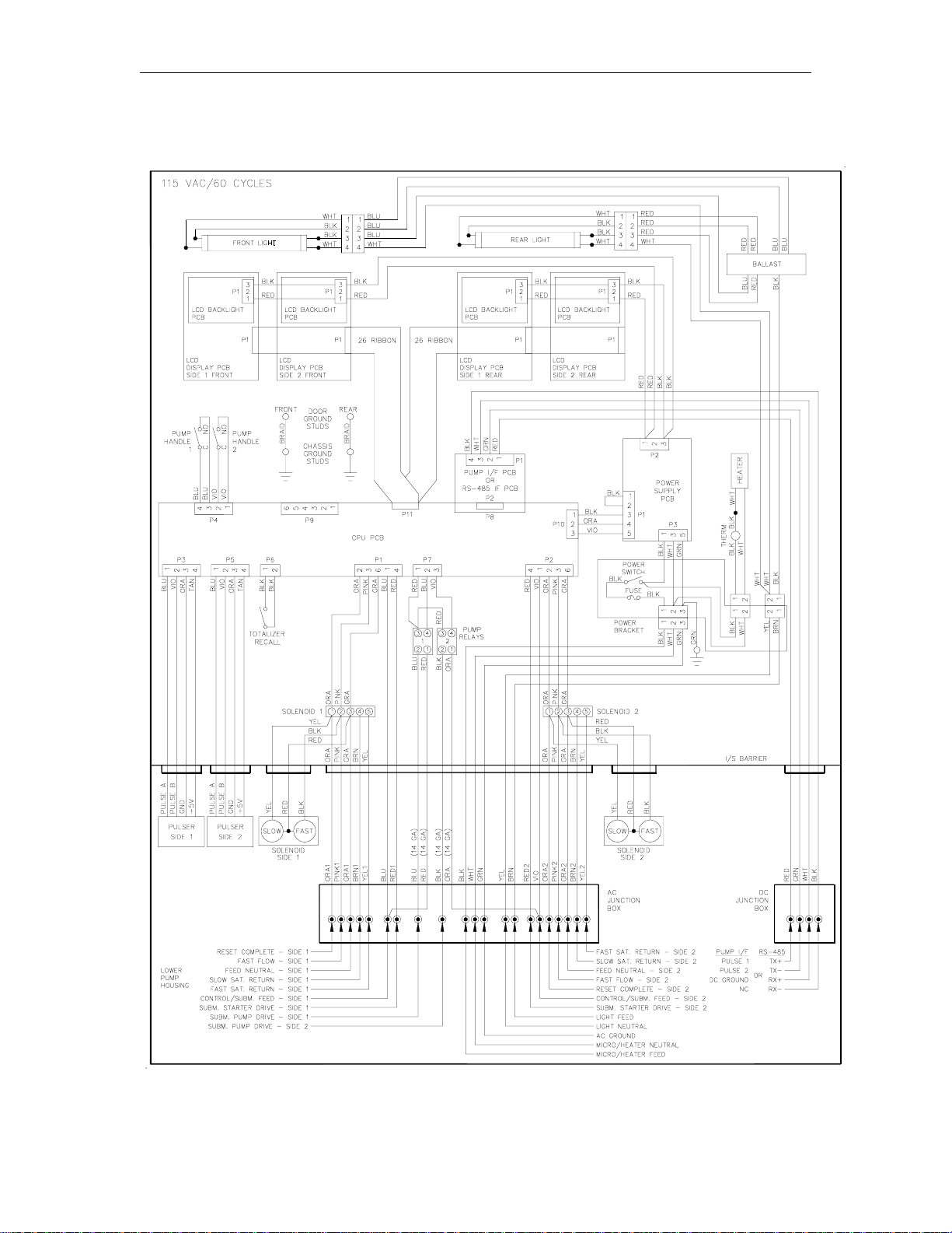
GASBOY Series 9800A
2-4 03/07/03
115VAC/60 CYCLE DISPENSER WIRING

Chassis Wiring
03/07/03 2-5
230VAC/50 CYCLE PUMP WIRING
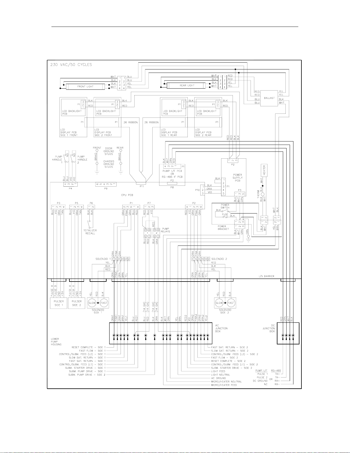
GASBOY Series 9800A
2-6 03/07/03
230VAC/50 CYCLE DISPENSER WIRING

Chassis Wiring
03/07/03 2-7
115VAC/60 CYCLE FRONT LOAD OPTION PUMP WIRING

GASBOY Series 9800A
2-8 03/07/03
115VAC/60 CYCLE FRONT LOAD OPTION DISPENSER WIRING

Chassis Wiring
03/07/03 2-9
230VAC/50 CYCLE FRONT LOAD OPTION PUMP WIRING

GASBOY Series 9800A
2-10 03/07/03
230VAC/50 CYCLE FRONT LOAD OPTION DISPENSER WIRING

Chassis Wiring
03/07/03 2-11

This manual suits for next models
20
Table of contents
Other Gasboy Dispenser manuals


Popular Dispenser manuals by other brands


Santos
Santos 34-1 User and maintenance manual

Dolphin
Dolphin Excel installation instructions

Ever Sharp Technology
Ever Sharp Technology ES2088 manual

Cornelius
Cornelius Quest Bib Option Kit installation manual

San Jamar
San Jamar Tear-N-Dry Essence quick start guide

ZEP
ZEP D-4000 Plus Service instructions


