Gasboy atlas User manual

Commercial and Retail Series
Atlas™Start-up/Service Manual
MDE-4334C

Computer Programs and Documentation
All Gasboy computer programs (including software on diskettes and within memory chips) and documentation are copyrighted by, and shall remain the property of, Gasboy. Such
computer programs and documents may also contain trade secret information. The duplication, disclosure, modification, or unauthorized use of computer programs or
documentation is strictly prohibited, unless otherwise licensed by Gasboy.
Federal Communications Commission (FCC) Warning
This equipment has been tested and found to comply with the limits for a Class A digital device pursuant to Part 15 of the FCC Rules. These limits are designed to provide
reasonable protection against harmful interference when the equipment is operated in a commercial environment. This equipment generates, uses, and can radiate radio frequency
energy, and if not installed and used in accordance with the instruction manual, may cause harmful interference to radio communications. Operation of this equipment in a
residential area is likely to cause harmful interference in which case the user will be required to correct the interference at his own expense. Changes or modifications not expressly
approved by the manufacturer could void the user’s authority to operate this equipment.
Approvals
Patents
Gasboy products are manufactured or sold under one or more of the following US patents:
Dispensers
Point of Sale/Back Office Equipment
Trademarks
5,257,720
D335,673
Gasboy, Greensboro, is an ISO 9001:2000 registered facility.
Underwriters Laboratories (UL):
UL File# Products listed with UL
MH4314 All dispensers and self-contained pumping
units
MH6418 Power operated Transfer Pump Models 25,
25C, 26, 27, 28, 72, 72S, 72SP, 72X, 73 and
1820
MH7404 Hand operated Transfer Pump Models 1230
Series, 1243 Series, 1520 and 1720 Series
MH10581 Key control unit, Model GKE-B Series
Card reader terminals, Models 1000, 1000P
Site controller, Model 2000S CFN Series
Data entry terminals, Model TPK-900 Series
Fuel Point Reader System
National Conference of Weights and Measures (NCWM) - Certificate of Compliance (CoC):
Gasboy pumps and dispensers are evaluated by NCWM under the National Type Evaluation Program (NTEP). NCWM has issued the following CoC:
CoC# Product Model # CoC# Product Model # CoC# Product Model #
95-179 Dispenser 9100 Retail Series, 8700
Series, 9700 Series 91-019 Dispenser 9100 Commercial
Series 05-002 Atlas 8700K, 8800K,
9100K,9200K,9800K
95-136 Dispenser 9800 Series 91-057 Controller 1000 Series FMS,
2000S-CFN Series
New York City Fire Department (NYFD):
NYFD C of A # Product
4823 9100A, 9140A, 9152A, 9153A,
9800A, 9840A, 9850A, 9852A,
9853A, 9140
4997 9822A, 9823A
5046 9100Q, 9140Q, 9152Q, 9153Q,
9800Q, 9840Q, 9852Q, 9853Q
5087 8753K, 8853K, 9153K, 9853K
(restricted to diesel and non-
retail gasoline sales)
5091 8752K, 9152K
5129 9122K, 9123K, 9822K, 9823K
California Air Resources Board (CARB):
Executive Order # Product
G-70-52-AM Balance Vapor Recovery
G-70-150-AE VaporVac
Registered trademarks
ASTRA®
Fuel Point®
Gasboy®
Keytrol®
Slimline®
Additional US and foreign trademarks pending.
Other brand or product names shown may be
trademarks or registered trademarks of their
respective holders.
Non-registered trademarks
Atlas™
Consola™
Infinity™
This document is subject to change without notice. · For information regarding Gasboy Literature, call (336) 547-5661
E-mail: literature@gasboy.com · Internet: http://www.gasboy.com
©2008 GASBOY · All Rights Reserved
Additional US and foreign patents pending.

MDE-4334C Atlas Start-up and Service Manual · April 2008 Page i
Table of Contents
1 – Read this First.....................................................................................................1-1
Introduction . . . . . . . . . . . . . . . . . . . . . . . . . . . . . . . . . . . . . . . . . . . . . . . . . . . . . . . . . . . . . . . . . . . . . 1-1
Purpose . . . . . . . . . . . . . . . . . . . . . . . . . . . . . . . . . . . . . . . . . . . . . . . . . 1-1
Important Information about Releases. . . . . . . . . . . . . . . . . . . . . . . . . . 1-1
Topics in this Section . . . . . . . . . . . . . . . . . . . . . . . . . . . . . . . . . . . . . . . 1-1
Who Should Use this Manual. . . . . . . . . . . . . . . . . . . . . . . . . . . . . . . . . 1-2
Service Protocol. . . . . . . . . . . . . . . . . . . . . . . . . . . . . . . . . . . . . . . . . . . 1-2
Related Documents . . . . . . . . . . . . . . . . . . . . . . . . . . . . . . . . . . . . . . . . 1-3
Abbreviations and Acronyms . . . . . . . . . . . . . . . . . . . . . . . . . . . . . . . . . 1-4
Common Terms Used . . . . . . . . . . . . . . . . . . . . . . . . . . . . . . . . . . . . . . 1-4
Model Information . . . . . . . . . . . . . . . . . . . . . . . . . . . . . . . . . . . . . . . . . . . . . . . . . . . . . . . . . . . . . . . . 1-5
Mechanical Retail Pump/Dispenser . . . . . . . . . . . . . . . . . . . . . . . . . . . . 1-5
Electronic Retail Pump/Dispenser . . . . . . . . . . . . . . . . . . . . . . . . . . . . . 1-6
Serial Number Plate and Date Codes . . . . . . . . . . . . . . . . . . . . . . . . . . 1-7
Atlas Model Number Table. . . . . . . . . . . . . . . . . . . . . . . . . . . . . . . . . . . 1-9
Options Overview. . . . . . . . . . . . . . . . . . . . . . . . . . . . . . . . . . . . . . . . . 1-10
2 – Important Safety Information...............................................................................2-1
3 – Start-up Procedures............................................................................................3-1
Introduction . . . . . . . . . . . . . . . . . . . . . . . . . . . . . . . . . . . . . . . . . . . . . . . . . . . . . . . . . . . . . . . . . . . . . 3-1
Purpose . . . . . . . . . . . . . . . . . . . . . . . . . . . . . . . . . . . . . . . . . . . . . . . . . 3-1
Important Information about Releases. . . . . . . . . . . . . . . . . . . . . . . . . . 3-1
Topics in this Section . . . . . . . . . . . . . . . . . . . . . . . . . . . . . . . . . . . . . . . 3-1
How to Use this Section. . . . . . . . . . . . . . . . . . . . . . . . . . . . . . . . . . . . . 3-1
Certificate of Conformance (CoC) Numbers . . . . . . . . . . . . . . . . . . . . . . . . . . . . . . . . . . . . . . . . . . . . 3-1
Start-up Checklists . . . . . . . . . . . . . . . . . . . . . . . . . . . . . . . . . . . . . . . . . . . . . . . . . . . . . . . . . . . . . . . 3-2
Installation Checklist . . . . . . . . . . . . . . . . . . . . . . . . . . . . . . . . . . . . . . . 3-2
Meter Calibration. . . . . . . . . . . . . . . . . . . . . . . . . . . . . . . . . . . . . . . . . . . . . . . . . . . . . . . . . . . . . . . . . 3-4
Gasboy Atlas (Gallon Unit of Measure) . . . . . . . . . . . . . . . . . . . . . . . . . 3-4
4 – Preventive Maintenance and Inspection.............................................................4-1
Introduction . . . . . . . . . . . . . . . . . . . . . . . . . . . . . . . . . . . . . . . . . . . . . . . . . . . . . . . . . . . . . . . . . . . . . 4-1
Purpose . . . . . . . . . . . . . . . . . . . . . . . . . . . . . . . . . . . . . . . . . . . . . . . . . 4-1
Important Information about Releases. . . . . . . . . . . . . . . . . . . . . . . . . . 4-1
Topics in this Section . . . . . . . . . . . . . . . . . . . . . . . . . . . . . . . . . . . . . . . 4-1
How to Use this Section. . . . . . . . . . . . . . . . . . . . . . . . . . . . . . . . . . . . . 4-1
Abbreviations and Acronyms . . . . . . . . . . . . . . . . . . . . . . . . . . . . . . . . . 4-1
Common Terms Used . . . . . . . . . . . . . . . . . . . . . . . . . . . . . . . . . . . . . . 4-2
Preventive Maintenance . . . . . . . . . . . . . . . . . . . . . . . . . . . . . . . . . . . . . . . . . . . . . . . . . . . . . . . . . . . 4-2
Maintenance Procedures and Parts. . . . . . . . . . . . . . . . . . . . . . . . . . . . 4-2
Maintenance of Vendor Supplied Parts . . . . . . . . . . . . . . . . . . . . . . . . . 4-3
Performing Inspections . . . . . . . . . . . . . . . . . . . . . . . . . . . . . . . . . . . . . . . . . . . . . . . . . . . . . . . . . . . . 4-3
Safety Warnings. . . . . . . . . . . . . . . . . . . . . . . . . . . . . . . . . . . . . . . . . . . 4-3
Replacements and Adjustments . . . . . . . . . . . . . . . . . . . . . . . . . . . . . . . . . . . . . . . . . . . . . . . . . . . . . 4-5
Filter Strainer Replacement . . . . . . . . . . . . . . . . . . . . . . . . . . . . . . . . . . 4-5
Adjusting the Belts (Suction Pumps only) . . . . . . . . . . . . . . . . . . . . . . . 4-5

Page ii MDE-4334C Atlas Start-up and Service Manual · April 2008
Preserving the Finish . . . . . . . . . . . . . . . . . . . . . . . . . . . . . . . . . . . . . . . . . . . . . . . . . . . . . . . . . . . . . .4-6
Preventive Maintenance Table. . . . . . . . . . . . . . . . . . . . . . . . . . . . . . . . . . . . . . . . . . . . . . . . . . . . . . .4-7
5 – Pump Programming............................................................................................ 5-1
Introduction. . . . . . . . . . . . . . . . . . . . . . . . . . . . . . . . . . . . . . . . . . . . . . . . . . . . . . . . . . . . . . . . . . . . . .5-1
Purpose. . . . . . . . . . . . . . . . . . . . . . . . . . . . . . . . . . . . . . . . . . . . . . . . . .5-1
Important Information about Releases . . . . . . . . . . . . . . . . . . . . . . . . . .5-1
Abbreviations and Acronyms
Common Terms Used . . . . . . . . . . . . . . . . . . . . . . . . . . . . . . . .5-1
Programming Overview . . . . . . . . . . . . . . . . . . . . . . . . . . . . . . . . . . . . . . . . . . . . . . . . . . . . . . . . . . . .5-2
Electronic Commercial Units (9800 Series) . . . . . . . . . . . . . . . . . . . . . .5-2
Electronic Retail Units. . . . . . . . . . . . . . . . . . . . . . . . . . . . . . . . . . . . . . .5-3
Mechanical Commercial Units. . . . . . . . . . . . . . . . . . . . . . . . . . . . . . . . .5-4
Configuring the 9800 Series. . . . . . . . . . . . . . . . . . . . . . . . . . . . . . . . . . . . . . . . . . . . . . . . . . . . . . . . .5-4
General Configuration Details. . . . . . . . . . . . . . . . . . . . . . . . . . . . . . . . .5-4
Configuration Steps. . . . . . . . . . . . . . . . . . . . . . . . . . . . . . . . . . . . . . . . .5-6
ATC Setup. . . . . . . . . . . . . . . . . . . . . . . . . . . . . . . . . . . . . . . . . . . . . . .5-11
Error Codes. . . . . . . . . . . . . . . . . . . . . . . . . . . . . . . . . . . . . . . . . . . . . .5-12
Programming 8800 Series Units. . . . . . . . . . . . . . . . . . . . . . . . . . . . . . . . . . . . . . . . . . . . . . . . . . . . .5-13
General Programming Details. . . . . . . . . . . . . . . . . . . . . . . . . . . . . . . .5-13
Display Conventions . . . . . . . . . . . . . . . . . . . . . . . . . . . . . . . . . . . . . . .5-15
Programming Steps for 8800 Series Units . . . . . . . . . . . . . . . . . . . . . .5-16
Level 1 Programming . . . . . . . . . . . . . . . . . . . . . . . . . . . . . . . . . . . . . .5-17
Level 2 Programming . . . . . . . . . . . . . . . . . . . . . . . . . . . . . . . . . . . . . .5-20
Level 3 Programming . . . . . . . . . . . . . . . . . . . . . . . . . . . . . . . . . . . . . .5-24
Option and Miscellaneous Programming/Data Acquisition. . . . . . . . . .5-26
Displaying Pump Totals . . . . . . . . . . . . . . . . . . . . . . . . . . . . . . . . . . . .5-27
Error Codes and Descriptions. . . . . . . . . . . . . . . . . . . . . . . . . . . . . . . .5-28
Programming 8700 Series Units. . . . . . . . . . . . . . . . . . . . . . . . . . . . . . . . . . . . . . . . . . . . . . . . . . . . .5-29
General Programming Details. . . . . . . . . . . . . . . . . . . . . . . . . . . . . . . .5-29
Programming Steps . . . . . . . . . . . . . . . . . . . . . . . . . . . . . . . . . . . . . . .5-29
6 – Electronic and Electrical Components................................................................ 6-1
Introduction. . . . . . . . . . . . . . . . . . . . . . . . . . . . . . . . . . . . . . . . . . . . . . . . . . . . . . . . . . . . . . . . . . . . . .6-1
Purpose. . . . . . . . . . . . . . . . . . . . . . . . . . . . . . . . . . . . . . . . . . . . . . . . . .6-1
Important Information about Releases . . . . . . . . . . . . . . . . . . . . . . . . . .6-1
Topics in this Section . . . . . . . . . . . . . . . . . . . . . . . . . . . . . . . . . . . . . . .6-1
How to Use this Section . . . . . . . . . . . . . . . . . . . . . . . . . . . . . . . . . . . . .6-1
Abbreviations and Acronyms . . . . . . . . . . . . . . . . . . . . . . . . . . . . . . . . .6-2
Electronics Highlights. . . . . . . . . . . . . . . . . . . . . . . . . . . . . . . . . . . . . . . . . . . . . . . . . . . . . . . . . . . . . .6-2
Retail Parts by Name . . . . . . . . . . . . . . . . . . . . . . . . . . . . . . . . . . . . . . .6-3
Retail and Commercial Parts by Number . . . . . . . . . . . . . . . . . . . . . . . .6-5
8800 Series Retail Electronics . . . . . . . . . . . . . . . . . . . . . . . . . . . . . . . .6-7
System and Component Overview . . . . . . . . . . . . . . . . . . . . . . . . . . . . .6-7
About Service Procedures . . . . . . . . . . . . . . . . . . . . . . . . . . . . . . . . . . . . . . . . . . . . . . . . . . . . . . . . . .6-8
Working on Electronic and Electrical Components. . . . . . . . . . . . . . . . . . . . . . . . . . . . . . . . . . . . . . . .6-9
Preparing for Service . . . . . . . . . . . . . . . . . . . . . . . . . . . . . . . . . . . . . . .6-9
Preventing ESD. . . . . . . . . . . . . . . . . . . . . . . . . . . . . . . . . . . . . . . . . . . .6-9
Hazardous Materials. . . . . . . . . . . . . . . . . . . . . . . . . . . . . . . . . . . . . . .6-10
Component Overview. . . . . . . . . . . . . . . . . . . . . . . . . . . . . . . . . . . . . . . . . . . . . . . . . . . . . . . . . . . . .6-11
PCAs . . . . . . . . . . . . . . . . . . . . . . . . . . . . . . . . . . . . . . . . . . . . . . . . . . . . . . . . . . . . . . . . . . . . . . . . .6-12
Atlas 9800 PCAs. . . . . . . . . . . . . . . . . . . . . . . . . . . . . . . . . . . . . . . . . .6-12
Atlas 9800 Parts. . . . . . . . . . . . . . . . . . . . . . . . . . . . . . . . . . . . . . . . . . . . . . . . . . . . . . . . . . . . . . . . .6-20
Atlas 9800 CPU Board (M06333KXXXX) . . . . . . . . . . . . . . . . . . . . . . .6-20

MDE-4334C Atlas Start-up and Service Manual · April 2008 Page iii
Atlas 9800 Power Supply (M07588A00X) . . . . . . . . . . . . . . . . . . . . . . 6-23
Atlas 9800 Serial EEPROM Board (M06656K00X) . . . . . . . . . . . . . . . 6-24
Atlas 9800 Pulse-out I/F Board with
EM Totalizer Drive (M06587A001). . . . . . . . . . . . . . . . . . . . . . . . . . . . 6-25
K-Pump RS-485 with Totalizer (M05248A001) . . . . . . . . . . . . . . . . . . 6-26
Accessing the Electronic Components . . . . . . . . . . . . . . . . . . . . . . . . . . . . . . . . . . . . . . . . . . . . . . . 6-27
Installing the Atlas 9800 Power Supply (M07588A00X) . . . . . . . . . . . . . . . . . . . . . . . . . . . . . . . . . . 6-27
Installing the Atlas 9800 CPU Board (M06333KXXXX). . . . . . . . . . . . . . . . . . . . . . . . . . . . . . . . . . . 6-28
Installing the Atlas 9800 Pulse-out I/F with EM Totalizer Drive Board (M06587A001) . . . . . . . . . . . 6-30
Jumpers JP1, JP2, and JP3. . . . . . . . . . . . . . . . . . . . . . . . . . . . . . . . . 6-30
Jumpers JP4 and JP5 . . . . . . . . . . . . . . . . . . . . . . . . . . . . . . . . . . . . . 6-30
Configurations . . . . . . . . . . . . . . . . . . . . . . . . . . . . . . . . . . . . . . . . . . . 6-31
Atlas 8800 Parts . . . . . . . . . . . . . . . . . . . . . . . . . . . . . . . . . . . . . . . . . . . . . . . . . . . . . . . . . . . . . . . . 6-32
T18994 Pump Interface PCA (Atlas 8800 only) . . . . . . . . . . . . . . . . . . 6-32
T20092 Pump Controller PCA (Atlas 8800 only) . . . . . . . . . . . . . . . . . 6-33
ATC Component Overview (Atlas 8800 only) . . . . . . . . . . . . . . . . . . . 6-35
T19405-G3 ATC T-meter Module PCA (Atlas 8800 only) . . . . . . . . . . 6-36
T17549-G1 Manager Keypad (Atlas 8800 only). . . . . . . . . . . . . . . . . . 6-37
T17622-G9 (.6 inch) Display Backlight PCA (Atlas 8800 only) . . . . . . 6-38
T17701-G1 LCD Display (.6 inch) (Atlas 8800 only) . . . . . . . . . . . . . . 6-38
Power Supplies . . . . . . . . . . . . . . . . . . . . . . . . . . . . . . . . . . . . . . . . . . . . . . . . . . . . . . . . . . . . . . . . . 6-39
T19868-G1 Main Power Supply. . . . . . . . . . . . . . . . . . . . . . . . . . . . . . 6-41
T19428-G1 IS Barrier Assembly ATC . . . . . . . . . . . . . . . . . . . . . . . . . 6-43
Q10131-03 Fuse . . . . . . . . . . . . . . . . . . . . . . . . . . . . . . . . . . . . . . . . . 6-43
Electro-mechanical Registers and Totalizers . . . . . . . . . . . . . . . . . . . . . . . . . . . . . . . . . . . . . . . . . . 6-43
About Displays . . . . . . . . . . . . . . . . . . . . . . . . . . . . . . . . . . . . . . . . . . . 6-43
Electronic Totalizer Display . . . . . . . . . . . . . . . . . . . . . . . . . . . . . . . . . 6-44
Electro-mechanical Totalizer Assembly . . . . . . . . . . . . . . . . . . . . . . . . 6-46
Pulsers. . . . . . . . . . . . . . . . . . . . . . . . . . . . . . . . . . . . . . . . . . . . . . . . . . . . . . . . . . . . . . . . . . . . . . . . 6-47
About Standard Pulsers . . . . . . . . . . . . . . . . . . . . . . . . . . . . . . . . . . . . 6-47
Testing Pulsers and IS Barriers . . . . . . . . . . . . . . . . . . . . . . . . . . . . . . 6-48
Pulser Drive Assembly. . . . . . . . . . . . . . . . . . . . . . . . . . . . . . . . . . . . . 6-49
About Ultra-Hi Pulsers . . . . . . . . . . . . . . . . . . . . . . . . . . . . . . . . . . . . . 6-49
7 – Hydraulic/Mechanical Components ....................................................................7-1
Introduction . . . . . . . . . . . . . . . . . . . . . . . . . . . . . . . . . . . . . . . . . . . . . . . . . . . . . . . . . . . . . . . . . . . . . 7-1
Purpose . . . . . . . . . . . . . . . . . . . . . . . . . . . . . . . . . . . . . . . . . . . . . . . . . 7-1
Important Information about Releases. . . . . . . . . . . . . . . . . . . . . . . . . . 7-1
Topics in this Section . . . . . . . . . . . . . . . . . . . . . . . . . . . . . . . . . . . . . . . 7-1
How to Use this Section. . . . . . . . . . . . . . . . . . . . . . . . . . . . . . . . . . . . . 7-2
Abbreviations and Acronyms . . . . . . . . . . . . . . . . . . . . . . . . . . . . . . . . . 7-2
Common Terms Used . . . . . . . . . . . . . . . . . . . . . . . . . . . . . . . . . . . . . . 7-2
Hydraulic and Mechanical Highlights. . . . . . . . . . . . . . . . . . . . . . . . . . . . . . . . . . . . . . . . . . . . . . . . . . 7-3
2-stage Solenoid Valve . . . . . . . . . . . . . . . . . . . . . . . . . . . . . . . . . . . . . 7-3
Meter . . . . . . . . . . . . . . . . . . . . . . . . . . . . . . . . . . . . . . . . . . . . . . . . . . . 7-4
General Service Procedures . . . . . . . . . . . . . . . . . . . . . . . . . . . . . . . . . . . . . . . . . . . . . . . . . . . . . . . . 7-6
Working on Hydraulic Components . . . . . . . . . . . . . . . . . . . . . . . . . . . . 7-6
About Servicing Hydraulic Components. . . . . . . . . . . . . . . . . . . . . . . . . 7-7
Servicing Seals, O-Rings, and Gaskets. . . . . . . . . . . . . . . . . . . . . . . . . 7-8
Pipes and Hydraulic Plumbing . . . . . . . . . . . . . . . . . . . . . . . . . . . . . . . . 7-8
Torque Specifications. . . . . . . . . . . . . . . . . . . . . . . . . . . . . . . . . . . . . . . 7-9
Purging Air from the System . . . . . . . . . . . . . . . . . . . . . . . . . . . . . . . . . . . . . . . . . . . . . . . . . . . . . . . 7-11
About the Purging System . . . . . . . . . . . . . . . . . . . . . . . . . . . . . . . . . . 7-11
Purging Product Lines (New Installations) . . . . . . . . . . . . . . . . . . . . . . 7-11

Page iv MDE-4334C Atlas Start-up and Service Manual · April 2008
Purging Pumps and Dispensers (with Fuel in Product Lines). . . . . . . .7-12
Measuring the Flow Rate . . . . . . . . . . . . . . . . . . . . . . . . . . . . . . . . . . . . . . . . . . . . . . . . . . . . . . . . . .7-14
Measuring Pressure and Vacuum . . . . . . . . . . . . . . . . . . . . . . . . . . . . . . . . . . . . . . . . . . . . . . . . . . .7-15
Using the Pressure Gauge . . . . . . . . . . . . . . . . . . . . . . . . . . . . . . . . . .7-15
Pressure Measuring Locations on Unit. . . . . . . . . . . . . . . . . . . . . . . . .7-16
Measuring Pressure Drop for Pumps and Dispensers . . . . . . . . . . . . .7-17
Analyzing Pressure Drop for Dispensers and Pumps. . . . . . . . . . . . . .7-18
Measuring Vacuum for Pump . . . . . . . . . . . . . . . . . . . . . . . . . . . . . . . .7-20
About Vacuum Readings . . . . . . . . . . . . . . . . . . . . . . . . . . . . . . . . . . .7-20
Measuring Dry Vacuum for Pump. . . . . . . . . . . . . . . . . . . . . . . . . . . . .7-20
Measuring Wet Vacuum and Pressure for Pump . . . . . . . . . . . . . . . . .7-21
Meter Calibration . . . . . . . . . . . . . . . . . . . . . . . . . . . . . . . . . . . . . . . . . . . . . . . . . . . . . . . . . . . . . . . .7-23
About Calibrating Meters. . . . . . . . . . . . . . . . . . . . . . . . . . . . . . . . . . . .7-23
CFT Meter Calibration Adjustment for Standard, Hi-Flow,
and Super-Hi Models (All Models Excluding 9850K and 9850KX) . . . .7-24
LC Meter Calibration Adjustment for Ultra-Hi Models 9850K
and 9850KX . . . . . . . . . . . . . . . . . . . . . . . . . . . . . . . . . . . . . . . . . . . . .7-26
Meters. . . . . . . . . . . . . . . . . . . . . . . . . . . . . . . . . . . . . . . . . . . . . . . . . . . . . . . . . . . . . . . . . . . . . . . . .7-27
About Meters. . . . . . . . . . . . . . . . . . . . . . . . . . . . . . . . . . . . . . . . . . . . .7-27
CFT Meters. . . . . . . . . . . . . . . . . . . . . . . . . . . . . . . . . . . . . . . . . . . . . .7-28
Repairing CFT Meters. . . . . . . . . . . . . . . . . . . . . . . . . . . . . . . . . . . . . .7-29
Replacing Cylinder Cover and Gasket (Cylinder Cover Leaks) . . . . . .7-30
Replacing O-Rings (Body and Cover Leaks) . . . . . . . . . . . . . . . . . . . .7-31
Calibrating Wheel Parts Repair. . . . . . . . . . . . . . . . . . . . . . . . . . . . . . .7-32
Replacing Piston Cups . . . . . . . . . . . . . . . . . . . . . . . . . . . . . . . . . . . . .7-32
Removing/Replacing the Shaft Seal and Gasket (Upper Seal Leaks) .7-34
LC Meters . . . . . . . . . . . . . . . . . . . . . . . . . . . . . . . . . . . . . . . . . . . . . . .7-35
Removing/Replacing LC Meters . . . . . . . . . . . . . . . . . . . . . . . . . . . . . .7-36
Filters and Strainers . . . . . . . . . . . . . . . . . . . . . . . . . . . . . . . . . . . . . . . . . . . . . . . . . . . . . . . . . . . . .7-37
About Filters . . . . . . . . . . . . . . . . . . . . . . . . . . . . . . . . . . . . . . . . . . . . .7-37
Servicing Filters. . . . . . . . . . . . . . . . . . . . . . . . . . . . . . . . . . . . . . . . . . .7-38
About Strainers . . . . . . . . . . . . . . . . . . . . . . . . . . . . . . . . . . . . . . . . . . .7-40
Servicing Strainers . . . . . . . . . . . . . . . . . . . . . . . . . . . . . . . . . . . . . . . .7-41
Hanging Hardware . . . . . . . . . . . . . . . . . . . . . . . . . . . . . . . . . . . . . . . . . . . . . . . . . . . . . . . . . . . . . . .7-41
About the Hanging Hardware . . . . . . . . . . . . . . . . . . . . . . . . . . . . . . . .7-42
Hoses and Flow Restrictors . . . . . . . . . . . . . . . . . . . . . . . . . . . . . . . . .7-42
Breakaway Valves. . . . . . . . . . . . . . . . . . . . . . . . . . . . . . . . . . . . . . . . .7-44
Testing Hose and Hanging Hardware Continuity . . . . . . . . . . . . . . . . .7-47
Internal Hose Retrievers and Clamps. . . . . . . . . . . . . . . . . . . . . . . . . .7-49
Pumping Unit . . . . . . . . . . . . . . . . . . . . . . . . . . . . . . . . . . . . . . . . . . . . . . . . . . . . . . . . . . . . . . . . . . .7-50
GPU Pumping Unit . . . . . . . . . . . . . . . . . . . . . . . . . . . . . . . . . . . . . . . .7-50
Servicing the Strainer Check Valve. . . . . . . . . . . . . . . . . . . . . . . . . . . .7-53
Servicing the Pressure Control Valve (PCV). . . . . . . . . . . . . . . . . . . . .7-55
Servicing the Bypass/Pressure Relief Valve (PRV) . . . . . . . . . . . . . . .7-56
Servicing the Rotor and Shaft Assembly. . . . . . . . . . . . . . . . . . . . . . . .7-58
XU2A Pumping Unit for 9850K . . . . . . . . . . . . . . . . . . . . . . . . . . . . . . .7-59
Sump for 9850K . . . . . . . . . . . . . . . . . . . . . . . . . . . . . . . . . . . . . . . . . .7-62
Pump Motor . . . . . . . . . . . . . . . . . . . . . . . . . . . . . . . . . . . . . . . . . . . . . . . . . . . . . . . . . . . . . . . . . . . .7-63
About Electric Motor for Self-contained Pump Units. . . . . . . . . . . . . . .7-63
Belts and Pulleys. . . . . . . . . . . . . . . . . . . . . . . . . . . . . . . . . . . . . . . . . .7-64
Belt Adjustment. . . . . . . . . . . . . . . . . . . . . . . . . . . . . . . . . . . . . . . . . . .7-65
Valves. . . . . . . . . . . . . . . . . . . . . . . . . . . . . . . . . . . . . . . . . . . . . . . . . . . . . . . . . . . . . . . . . . . . . . . . .7-66
Solenoid Valves . . . . . . . . . . . . . . . . . . . . . . . . . . . . . . . . . . . . . . . . . .7-66
Solenoid Valve and Filter Manifold . . . . . . . . . . . . . . . . . . . . . . . . . . . .7-68
Solenoid Valves for 9x40, 9850 and 9x53 with Satellite Outlet Piping .7-70

MDE-4334C Atlas Start-up and Service Manual · April 2008 Page v
Meter Check Valve. . . . . . . . . . . . . . . . . . . . . . . . . . . . . . . . . . . . . . . . 7-71
Shear Valves . . . . . . . . . . . . . . . . . . . . . . . . . . . . . . . . . . . . . . . . . . . . 7-72
T-52A Pressure Regulator Valve Option . . . . . . . . . . . . . . . . . . . . . . . 7-74
Vapor Recovery Stage 2 Balance Type . . . . . . . . . . . . . . . . . . . . . . . . . . . . . . . . . . . . . . . . . . . . . . 7-74
Troubleshooting . . . . . . . . . . . . . . . . . . . . . . . . . . . . . . . . . . . . . . . . . . 7-75
Mechanical Computers . . . . . . . . . . . . . . . . . . . . . . . . . . . . . . . . . . . . . . . . . . . . . . . . . . . . . . . . . . . 7-75
8 – Troubleshooting Tables ......................................................................................8-1
Introduction . . . . . . . . . . . . . . . . . . . . . . . . . . . . . . . . . . . . . . . . . . . . . . . . . . . . . . . . . . . . . . . . . . . . . 8-1
Purpose . . . . . . . . . . . . . . . . . . . . . . . . . . . . . . . . . . . . . . . . . . . . . . . . . 8-1
Important Information about Releases. . . . . . . . . . . . . . . . . . . . . . . . . . 8-1
Topics in this Section . . . . . . . . . . . . . . . . . . . . . . . . . . . . . . . . . . . . . . . 8-1
How to Use this Section. . . . . . . . . . . . . . . . . . . . . . . . . . . . . . . . . . . . . 8-1
Troubleshooting Tables (Commercial Electronic and Retail Electronic Units) . . . . . . . . . . . . . . . . . . 8-2
Sample Troubleshooting Form. . . . . . . . . . . . . . . . . . . . . . . . . . . . . . . . 8-3
Priority Codes. . . . . . . . . . . . . . . . . . . . . . . . . . . . . . . . . . . . . . . . . . . . . 8-3
Table 1: Communications to the Console . . . . . . . . . . . . . . . . . . . . . . . 8-4
Table 2: Fuel Delivery (All Units) . . . . . . . . . . . . . . . . . . . . . . . . . . . . . . 8-5
Table 3: Electronic Displays, Electric Reset and Calibration . . . . . . . . 8-6
Table 4: Error Codes 10-44 . . . . . . . . . . . . . . . . . . . . . . . . . . . . . . . . . . 8-7
Table 5: Handle Responses, Leaks, Noise, and Presets (All Units) . . . 8-8
Table 6: Repeated Problems and STPs. . . . . . . . . . . . . . . . . . . . . . . . . 8-9
9 – Wiring and Configuration ....................................................................................9-1
Introduction . . . . . . . . . . . . . . . . . . . . . . . . . . . . . . . . . . . . . . . . . . . . . . . . . . . . . . . . . . . . . . . . . . . . . 9-1
Purpose . . . . . . . . . . . . . . . . . . . . . . . . . . . . . . . . . . . . . . . . . . . . . . . . . 9-1
Important Information about Releases. . . . . . . . . . . . . . . . . . . . . . . . . . 9-1
Topics in this Section . . . . . . . . . . . . . . . . . . . . . . . . . . . . . . . . . . . . . . 9-1
Cable Block Diagrams. . . . . . . . . . . . . . . . . . . . . . . . . . . . . . . . . . . . . . . . . . . . . . . . . . . . . . . . . . . . . 9-1
Block Diagram K-Pump Retail M04885 . . . . . . . . . . . . . . . . . . . . . . . . . 9-1
Block Diagram K-Pump Commercial M05193 . . . . . . . . . . . . . . . . . . . . 9-1
Atlas Hydraulics, Bezel and Door Configurations . . . . . . . . . . . . . . . . . . . . . . . . . . . . . . . . . . . . . . . . 9-2

Page vi MDE-4334C Atlas Start-up and Service Manual · April 2008
This page is intentionally left blank.

MDE-4334C Atlas Start-up and Service Manual · April 2008 Page 1-1
Introduction Read this First
1 – Read this First
Introduction
Purpose This section contains a general introduction, service protocol, safety and model number
information.
Sections of this manual combine to provide start-up and service information for Atlas pumps
and dispensers. This manual is a general service guide and not a replacement for Gasboy Atlas
Certified Training. Certified Training includes instructions in safety procedures, use of test
equipment and common tools, wiring requirements, and electrical service procedures. The
sections in this manual cover the following topics.
Topics Page
Read this First 1-1
Important Safety Information 2-1
Start-up Procedures 3-1
Preventive Maintenance and Inspection 4-1
Pump Programming 5-1
Electronic and Electrical Components 6-1
Hydraulic/Mechanical Components 7-1
Troubleshooting Tables 8-1
Wiring and Configuration 9-1
Important Information about Releases
Sections of this manual may be released independently of each other to supply the most
current data. Information about release date and version for independently released sections
will be included in the section title and footer of the document. Refer to the Gilbarco Online
document resource “GOLD” for the latest update.
This section was last updated in January 2007.
Topics in this Section
Topic Page
Model Information 1-5

Read this First Introduction
Page 1-2 MDE-4334C Atlas Start-up and Service Manual · April 2008
Who Should Use this Manual
This manual is intended for Gasboy Atlas Authorized Service Contractors (ASCs) who have
been trained and certified by attending Gasboy Certified Training classes. These ASCs should
be aware of the safety requirements and basic troubleshooting techniques, such as reading a
volt/ohmmeter, reading pressure, and so on, and understand the differences between various
Gasboy Atlas products, options, and functionalities.
If you have not attended the Gasboy training, contact the Gasboy Training Department. See
Whom to Contact at Gasboy below for contact information.
Service Protocol
Requesting Further Technical Assistance
A Service Technician requesting technical assistance should do the following:
1Be available at the site.
2When placing the call, ensure that the following are available:
• Unit model and serial number
• Site name and telephone number
• Your technician number
• Problem description and history
• All required recommended spare parts
• Manuals available for reference
3Call the Technical Support department (1-800-444-5529). Refer to the Customer Service
Report (CSR) number, if previously assigned.
Using Replacement Parts
Use only genuine Gasboy Atlas replacement parts. Use of other parts will void warranty and
could affect unit conformance to various national, local, or state codes.
Whom to Contact at Gasboy
Information Required Contact Details
Schedule training Gasboy Training Department
TechnicalT[email protected]
Technical Assistance, Customer Service and
Warranty Service Gasboy Technical Support at
1-800-444-5529
Helpdesk@gasboy.com
Explanation of Gasboy’s warranty policy Contact your local Gasboy Distributor for assistance.
Technical literature, parts manuals, and other
documents Gasboy Literature Department at (336) 547-5661

MDE-4334C Atlas Start-up and Service Manual · April 2008 Page 1-3
Introduction Read this First
Related Documents
The following documents may be helpful when servicing the Gasboy Atlas equipment.
See P-7001 for a complete listing of documents available. Contact the Literature Department
(336-547-5661) for information regarding Gasboy Atlas documentation.
Document Number Description
C35963 CFN Islander II Installation Manual
FE-356 Atlas Dispenser Wiring Diagram
FE-357 Atlas Pump Field Wiring Diagram
FE-361 Atlas Satellite Field Wiring Diagram
Handbook 44 NIST Handbook 44
MDE-4255 Gasboy Warranty
MDE-4319 TopKAT Installation Manual
MDE-4331 Atlas Installation Manual
MDE-4333 Atlas Site Preparation Manual
MDE-4363 Atlas Owner’s Manual
MDE-4403 Atlas Operator’s Programming Quick Reference Card
MDE-4404 Atlas Technician Programming Quick Reference Card
PT-1949 Atlas Illustrated Parts Manual
PT-1950 Atlas Recommended Spare Parts Manual
RP100 PEI Recommended Practices for Underground Liquid Storage Systems
RP400 PEI Recommended Procedures for Testing Electrical Continuity of Petroleum
Dispensing Systems
Note: In addition to these documents, Gasboy Atlas marketing and information sheets are also
sources of information.

Read this First Introduction
Page 1-4 MDE-4334C Atlas Start-up and Service Manual · April 2008
Abbreviations and Acronyms
Term Description
ASC Authorized Service Contractor
CFN Cash Flow Network
CFR Code of Federal Regulations
MOC Major Oil Company
NIST National Institute of Standards and Technology
NEC National Electrical Code
NFPA National Fire Protection Association
OSHA Occupational Safety and Health Association
PIN Personal Identification Number
POS Point of Sale. Console or register that controls the pump dispenser for retail applications.
PPU Price Per Unit (that is, price per gallon or liter)
STP Submerged Turbine Pump
W&M Weights and Measures
Common Terms Used
Term Description
Dispenser Unit supplied by a Submerged Turbine Pump (STP)
Dual Hose Same as Twin Hose
Pump Unit that contains a self-contained pumping unit
Two-wire Proprietary communication system for Atlas 8800 series units

MDE-4334C Atlas Start-up and Service Manual · April 2008 Page 1-5
Model Information Read this First
Model Information
Mechanical Retail Pump/Dispenser
The following illustration displays the external components of a Gasboy pump/dispenser
(Mechanical Retail Unit). Mechanical units have mechanical type displays as opposed to
electronic digital type displays. In units that are Commercial instead of Retail, the external
components are the same, with the exception that they do not have a Monetary Sale amount, a
Price Per Unit (PPU) display, or Monetary Totalizer display.
Figure 1-1: Atlas Mechanical Retail Unit
Boot Area Total Monetary Sale Display
Volume Dispensed Display
Access Door
Door Lock
Nozzle and
Pump Handle
On/Off Lever
Control
Warning Labels
PPU Display
Mechanical Retail Unit
Monetary Totalizer Volume Totalizer
Read this First Model Information
Page 1-6 MDE-4334C Atlas Start-up and Service Manual · April 2008
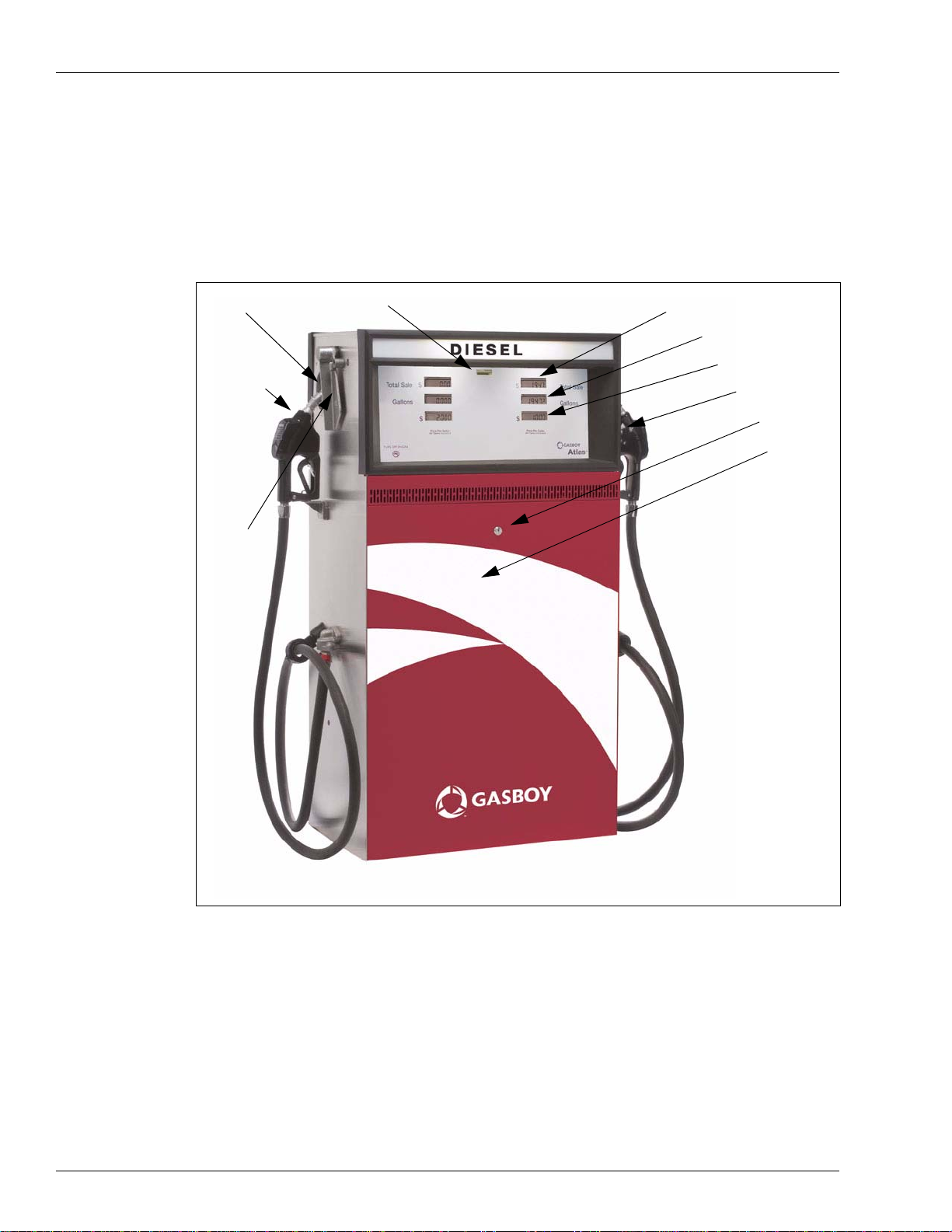
Electronic Retail Pump/Dispenser
The following illustration displays the external components of a Gasboy pump/dispenser
(Electronic Retail Unit). Electronic units have digital displays as opposed to mechanical
displays. In units that are Electronic Commercial instead of Retail, the external components
are the same, with the exception that they do not have a Monetary Sale amount, a PPU display,
or Monetary Totalizer display.
Figure 1-2: Atlas Electronic Retail Unit
Boot Area Digital Main Display
Price Per Unit
Warning Label
Door Lock
Access Door
Nozzle and
Pump Handle
Electro-mechanical Totalizer
Electronic Retail Unit Volume Dispensed Display
On/Off Lever
Control

MDE-4334C Atlas Start-up and Service Manual · April 2008 Page 1-7
Model Information Read this First
Serial Number Plate and Date Codes
A two-letter date code is stamped on the serial number plate before the serial number. This
code shows the month and year of manufacture. For warranty purposes, refer to the date code
to determine the age of the equipment. The serial number plate is located on the “A” side at the
bottom of the unit attached to the inside of the frame.
Refer to the following tables to determine the date code on a Gasboy pump or dispenser:
Month Codes
A = January E = May J = September
B = February F = June K = October
C = March G = July L = November
D = April H = August M = December
Year Codes
P = 2005 U = 2009
R = 2006 W = 2010
S = 2007 X = 2011
T = 2008 Y = 2012
Figure 1-3: Serial Number/Model Identification
Serial Number
Model Number
For example: A serial number plate stamped “BP AT000199” contains the following
information:
• Date code [BP] - This unit was manufactured in B=February, P=2005.
• Serial Number [AT000199]

Read this First Model Information
Page 1-8 MDE-4334C Atlas Start-up and Service Manual · April 2008
Listing of Atlas Model Suffixes
The following is a list of options that are available on some models. See Atlas Model Number
Table on page 1-9 for information on options that are available for a particular unit.
• CX - 10:1 Pulser, Quantity
• CC - 100:1 Pulser, Quantity
• CM - 100:1 Pulser, Money
• D9 - TopKAT Mounting Kit
• F - Internal Filter Adapter
• I - Internal Hose Retrievers
• J - Manual Reset (Export only)
•K-HandCrank
• L - Lighted Display Panel
• PP - Slowdown Valve
• PPS - Satellite Internal Piping - 9850K
• R - Liters Registration
• S - Internal Satellite Piping
• SS - Stainless Steel - All Panels
• SSA - Stainless Steel - Front & Back
• SSTS - Stainless Steel - Top & Sides
• TW1 - Dual Hose Single Product
• TW2 - Dual Hose Dual Product
• TW3 - Satellite Combo Unit
• X - Remote Dispenser
• X B - Display Battery Backup
• 25 - 230VAC, 50 Hz
• 35 - 380VAC, 50 Hz
• 36 - 380VAC, 60 Hz
Model Series
Series Description
9100K Mechanical Commercial Pumps & Dispensers
9800K Electronic Commercial Pumps & Dispensers
8700K Mechanical Retail Pumps & Dispensers
8800K Electronic Retail Pumps & Dispensers
Model Flow Rates
Series Designation (digits 1 and 2) Flow Rate Designation (digits 3, 4
and 5) Flow Rate Quantity
91/98/87/88 52K 15 GPM (57 LPM)
91/98/87/88 53K 22 GPM (83 LPM)
91/98/87/88 40K 40 GPM (151 LPM)
98 50K 50GPM (190 LPM)
Note: The flow rates shown are under ideal conditions and will vary depending upon the
hanging hardware involved, Submerged Turbine Pump (STP) sizing, number of units
dispensing at the same time, and inlet piping to the unit. These are not guaranteed flow
rates.

MDE-4334C Atlas Start-up and Service Manual · April 2008 Page 1-9
Model Information Read this First
Atlas Model Number Table
The Atlas model number uses a series of four numbers and five letters stamped into the serial
plate to denote the machine type and configuration. Refer to the following table to determine
the dispenser/pump type that is denoted on the serial plate.
Gasboy Atlas Model Code
RETAIL MODEL
CODE
BREAKDOW
COMMERCIAL
MODEL CODE
BREAKDOWN
8 X X X X X X X X 9 X X X X X X X X
Product Name: Product Name:
ATLAS 8ATLAS 9
Product Series: Product Series:
- Retail,
Mechanical 7- Commercial,
Mechanical Non-
Computing
1
- Retail, Electronic 8- Satellite 2
Type: - Commercial
Electronic 8
- Full Size Cabinet 5Type:
Flow Rates: - Narrow 1
- Ultra-Hi
Gallonage (40 to
50 gpm)
0- Compact Cabinet 2
- Not used 1- Full Size Cabinet 4
- Std Gallonage
(10 to 15 gpm) 2- Full Size Cabinet 5
- Hi Gallonage (18
to 22 gpm) 3Flow Rates:
Hydraulic Series - Ultra-Hi
Gallonage(40 to50
gpm)
0
- Murray A- Not used 1
- Gasboy
Hydraulics with
Gibarco C meter
Q- Std Gallonage 10
to 15 gpm) 2
- Gilbarco®
Hydraulics with
CFT meter
K- Hi Gallonage 18
to 22 gpm) 3
- Tokheim®
Hydraulics E- Variable (10 to 50
gpm) 5
Pump or
Dispenser - 21 6 High Speed
Satellite 6
- Pump Blan
kHydraulics Series:
- Dispenser X- Murray A
Hydraulic
Configuration - Gasboy Q
- 1 Grade, 1 Hose Bla
nk Bla
nk Bla
nk - Improved Gasboy K
- 1 Grade, 2 Hose T W 1 - Tokheim
Hydraulics E

Read this First Model Information
Page 1-10 MDE-4334C Atlas Start-up and Service Manual · April 2008
Options Overview
TopKAT™
The TopKAT Fuel Management System (FMS) can be ordered factory mounted on any 9800
unit. This Plug and Play option increases the ease of installation and provides customers with a
user-friendly fuel reporting system. The TopKAT system is also available as a pedestal
mounted unit and for use with mechanical pumps.
Electric Keytrol (EK)
The Electric Keytrol can be ordered factory mounted on the 9100 series. The EK provides
each customer with a personal key slot and totalizer to record their fueling amounts.
Configurations are available for both single and twin units.
Vapor Recovery
Balanced Vapor Recovery kits will be available for all K pump units. There will be two kits
available: Vapor Recovery Complete and Vapor Recovery kit. The Vapor Recovery Complete
kit will provide everything needed for a balanced system from the high hose retriever to the
splitter, all the way to the nozzle. The Vapor Recovery kit is a retrofit kit used when providing
your own vapor recovery system. This kit will provide a new nozzle boot and hook to allow a
stage two nozzle to be mounted on the dispenser.
High Hose Retriever
High Hose Retrievers are also available for standard hoses. Hose clamps are available for a
variety of hose sizes, up to lengths of 15".
Internal Hose Retriever
Internal Hose Retrievers are also available for all Atlas Pump models.
Satellite Piping
Satellite Piping is available on all remote dispensers and the 9850 pump. This option will
provide the internal piping needed to connect to a 9215 or 9216 satellite dispenser.
Hand Crank
Hand Cranks are available for installations in locations where power availability is a concern.
This option is only available for suction pumps.
- 2 Grades, 2
Hoses T W 2 Pump or Dispenser
- Combo T W 3 - Pump 0
- Dispenser X
Hydraulic
Configuration
- 1 Grade, 1 Hose Blank Blank Blank
- 1 Grade, 2 Hoses T W 1
- 2 Grades, 2
Hoses T W 2
- Combo T W 3
Gasboy Atlas Model Code

MDE-4334C Atlas Start-up and Service Manual · April 2008 Page 1-11
Model Information Read this First
Solenoid Valve
A two-stage slow down valve is available for units in retail applications. This option is
standard on all remote dispensers.
Pulse Output
Pulse Output is available for all 9800 pump models and some 8800 models. The pulse output
board for the 8800 model will be different from the 9800 model. Veeder-Root pulsers will be
provided for mechanical units when specified. An additional Pulse Output board must be
ordered when connecting an electronic unit to an FMS requiring mechanical type pulses.
Factory installation as well as field retrofit kits will be available for all Pulse Output options.
RS-485 Interface
When connecting a 9800 model to a Gasboy Cash Flow Network (CFN) or TopKAT system,
an RS-485 interface board must be installed in the unit. The interface can be ordered and
installed at the factory. Field installations kits are also available.
Note: The RS-485 interface board is not available for the 8800 model.
Battery Backed Power Supply
The battery backed power supply is available on all 9800 models. This option is required for
units being used in a retail application. If power is lost to the unit, the battery will allow the
last transaction amount to remain on the display for a period of time specified by weights and
measures. The 8800 series unit display is backed by a super cap that performs a similar
function.
Manual Reset
Manual resets are available for mechanical units and export orders only.

Read this First Model Information
Page 1-12 MDE-4334C Atlas Start-up and Service Manual · April 2008
This page is intentionally left blank.
Other manuals for atlas
1
Table of contents
Other Gasboy Dispenser manuals


Popular Dispenser manuals by other brands

ASI
ASI 0338 Installation & operation instructions

Graco
Graco E-Flo iQ Operation guide

Lantheus Medical Imaging
Lantheus Medical Imaging CALIDOSE DISPENSER Operation instructions

rosseto
rosseto EZ-PRO 1W quick start guide

DR.SCHUMACHER
DR.SCHUMACHER SPE 500 operating instructions

Bradley
Bradley 6A01-110000 quick start guide


