GasDog GD-600 User manual
www.gasdog.com +86 773-280-9002
GD-600 User Manual
Industrial Fixed Detector
Please read carefully before using
1
Foreword
You are welcome to use the instrument of this product, and hope that this manual will bring
you convenience when you use the instrument. If you find any unclear, wrong or excessively
lengthy place in this manual, please contact the agent or after-sales service department in time.
Before you perform any operation on this instrument, please read this operation manual
carefully, and keep the manual properly so that you can refer to it in time for help in the future.
It is forbidden to disseminate all the contents of this manual without permission;
this manual only provides relevant information.
The company is committed to continuous improvement of product performance, and the
company reserves the right to improve any content in the manual without prior notice.
Please refer to the actual product for the color and style of the product and product.
www.gasdog.com +86 773-280-9002
2

Foreword
1. Instructions before use
2. Attentions
3. Product Description
4. Product features
5. Attachment configuration list
6. Technical Parameters
7. Instrument installation
8. Remote control instruction
9. Function Description
1. Power On/Off
1.1 Power On
1.2 Power Off
2. User Interface
2.1 Detection interface description
2.2 Main menu interface operation
2.3 Calibration
2.3.1 Fresh air/zero calibration
2.3.2 Span Calibration
2.4 Alarm set
2.4.1 High alarm value, low alarm value
2.5 Monitor
2.5.1 Pump On/Off
2.5.2 Address
2.5.3 Current Setting
2.5.4 Relay
2.5.5 Reset
2.5.6 Language Setting
2.6 Info
2.6.1 Monitor Info
2.6.2 Sensor Info
2.6.3 Firmware Upgrade
10. Common faults and solutions
11. Terms of Service
12. National standards for product development, design
and production
14
15
15
15
15
16
16
17
17
17
18
20
20
21
21
21
22
22
23
24
24
24
24
24
25
25
26
---------------------------------------------------
------------------------------------
---------------------------------------------
--------------------------------------
------------------------------------------
----------------------------
------------------------------------
-----------------------------------
------------------------------
----------------------------------
------------------------------------------
----------------------------------------------
----------------------------------------------
------------------------------------------
------------------------
------------------------
-------------------------------------------
--------------------------
-----------------------------------
---------------------------------------------
------------------
------------------------------------------------
-----------------------------------------
----------------------------------------------
---------------------------------------
-------------------------------------------------
-------------------------------------------------
-----------------------------------
---------------------------------------------------
-------------------------------------------
-------------------------------------------
------------------------------------
---------------------------
------------------------------------------
-----------
2
4
4
6
6
6
7
8
Contents
www.gasdog.com +86 773-280-9002
3

1` Please read carefully before using
Anyone who may use, maintain or repair the instrument should read this operating
manual carefully and only follow the operating manual to achieve the design level. Otherwise
the instrument will not work properly and will cause malfunction and damage to the
instrument.
Warning:
●Before using the instrument, please read the product manual carefully.
●It is strictly forbidden to open the cover when the power is on at the scene.
●It is strictly forbidden to replace the sensor with power on.
●The installation, debugging, setting and other operations must be carried out by
professionals.
● Gas calibration inspection should be carried out regularly, and the sensors that have
exceeded the valid period of use and have faults should be replaced in time.
●It is strictly forbidden to input gas with a gas concentration higher than the measuring
range to impact the sensor.
●Prevent the instrument from falling from a high place or subject to severe shocks.
●It is strictly forbidden to expose the instrument to a high-concentration corrosive gas
environment to work for a long time to prevent damage to the sensor.
●It is strictly forbidden to use it under high temperature and high humidity. If the humidity is
high, it must be equipped with a filter dehumidification device.
●Users are not allowed to repair or replace parts without authorization.
●Man-made damage is not covered by the warranty.
●It is not allowed to change the components or structures that affect the explosion-proof
performance at will, so as not to affect the explosion-proof performance.
www.gasdog.com +86 773-280-9002
4

2` Attentions
●Electricity safety: Ensure that the instrument shell is properly grounded.
●For safety reasons, this product can only be operated and maintained by professionals,
and this manual must be fully read and understood before operation and maintenance.
●Because the instrument is a bit heavy, at least two people are required when installing
it, pay attention to it, and carry it carefully. Otherwise, it may cause physical injury.
●When carrying the instrument, please wear gloves, otherwise it may cause
injury.
●During the installation process, be careful not to allow wire heads or other debris to enter
the left channel port of the instrument, otherwise it may cause fire, malfunction, or
malfunction.
Calibration warning:
●The gas detection instrument is a safety and life-saving measuring instrument. In order to
ensure the accuracy of measurement, toxic and catalytic combustible gas sensors should
be calibrated at least once every six months, and infrared sensors should be calibrated
once a year.
●The gas detector needs to be carefully tested or calibrated after an alarm
occurs.
www.gasdog.com +86 773-280-9002
5
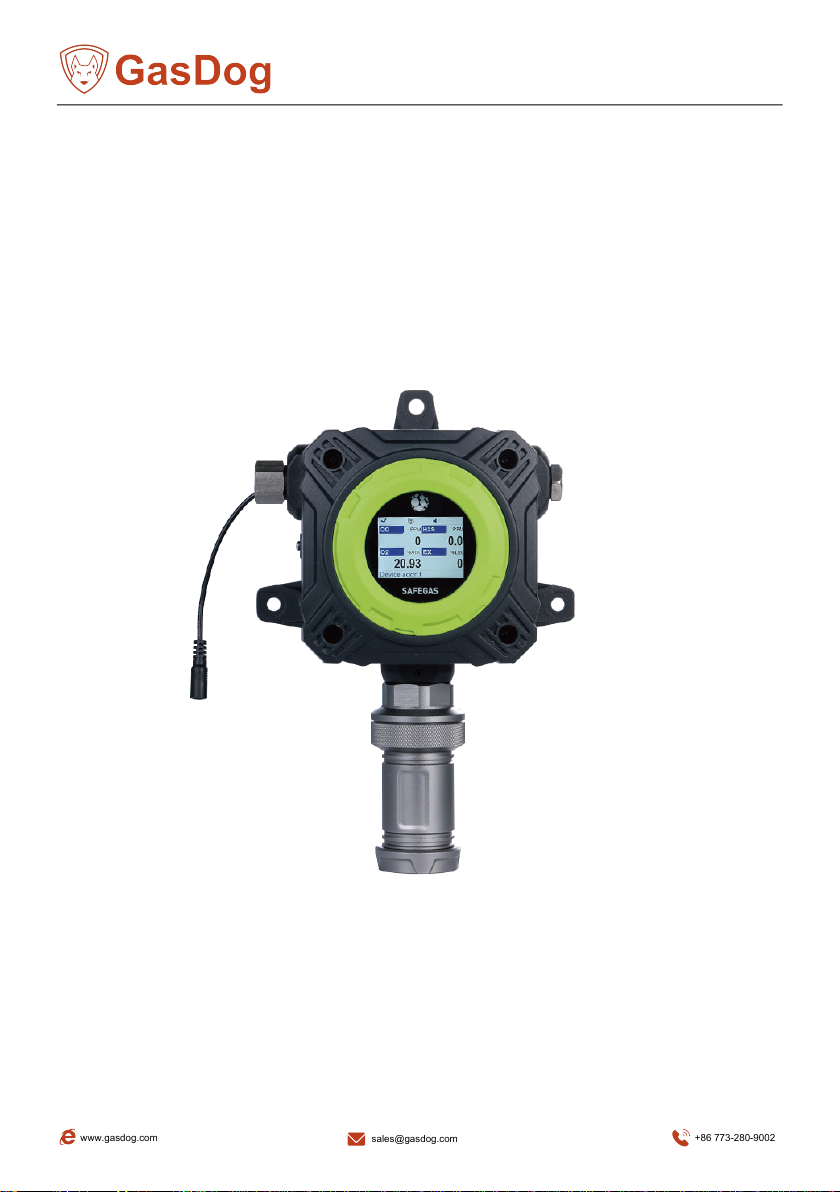
3` Product Description
GD700 Industrial Fixed Detector is a fixed pump suction detection instrument used in
complex working environments such as emission gas, oil and gas industry,
pipelines,laboratories, etc. Its built-in brushless pump and suction sampling method make the
detection fast and accurate. It committed to providing users with a reliable, accurate and safe
gas detection program.
4` Product features
2.4-inch high-definition color screen, wide viewing angle, low power
consumption Built-in micro sampling pump
4-20mA current signal, RS485 digital signal, 1 set of relay signal output
Infrared remote control, convenient and quick
Supports multiple gas units switch
5` Attachment configuration list
Standard accessories:
(1) One gas detector
(2) One infrared remote controller
(3) One water and dust filter
(4) One manual
(5) Certificate of conformity, warranty
card (6) Packing box
Optional accessories:
(1) Switching power
supply (2) Alarm light
(3) High temperature
probe (4) Mounting
brackets
(5) Power adapter(24V
DC)(6) Other
www.gasdog.com +86 773-280-9002
6

6` Technical Parameters
Product size: 286*202*96mm (H x W x D)
Product weight: 3.4kg (3.8kg with alarm light)
Sensor: Electrochemical principle, PID principle, infrared principle, catalytic combustion
principle Gas measurement range: To be specified
Resolution: To be specified
Precision: ≤±5%F.S or ≤±10%F.S (depend on sensor type)
Pump flow: 0.6(±0.1)L/Min
Display: 2.4-inch high-definition color display
Display content: gas molecular formula, concentration, unit, pump status, etc.
Alarm: buzzer, alarm status prompt on the display
Power supply: 12~24V DC
Installation method: wall-mounted
Working hours: 24 hours uninterrupted monitoring
Language: Chinese and English
Expansion: PC software
Humidity: 0~95%RH (non-condensing) (optional external filter will be needed if the humidity
is too high)
Temperature: -10℃~ +55℃ (optional sampling probe will be needed if the temperature is
too high) Explosion-proof grade: Ex d IIC T6 Gb
www.gasdog.com +86 773-280-9002
7

7` Instrument installation
Product structure
Wire connection
port
Shell ground
terminal
Screw fixing
hole
Alarm light
(optional)
Gas inlet
Gas chamber
Display
Status indicator
Infrared signal
receiving port
Wire
connection
port
Gas outlet
Screw fixing hole
Water and dust filter
www.gasdog.com +86 773-280-9002
8

* As shown in the figure, the housing grounding
mark " ", the instrument must be
properly grounded to avoid personal safety
accidents or instrument damage caused by
leakage or static electricity.
Installation types
GD700 is a pump suction detector, which can be connected to tube/hose for
detection, and the installation position can be selected flexibly.
Wall-mounted: This installation method is often selected for normal indoor inspection.
According to the nuts and spring washers, and then use 6x30mm nuts and spring washers to
fix the expansion bolts on the wall, as shown.
size of the hole of the detector (above), fix three 6mm expansion bolts on the wall, fix them
with screws,
Note: The installation location must be well
grounded or insulated. Leakage of electricity may
cause the detector to work abnormally.
*Other installation methods such as horizontal pipe,
vertical pipe can be adjusted according to site conditions
286.85
125.00
237.00
180.00
3-φ8.00
96.50
The detector installation avoids the following environmental influences:
●Environment temperature over device working temperature range.
●Environment humidity over device working humidity range.
●Environment pressure over device working pressure range
●High wind speed.
●Mechanical vibration.
●Strong electromagnetic radiation environment.
●high voltage environment.
●Electricity leakage.
Installation size
The upper and lower spacing of the three fixed holes of the instrument and the size of the
device are as shown in the figure below.
The left side is the wiring area, and the right side is the alarm.
www.gasdog.com +86 773-280-9002
9

-10-
Gas outlet
Sampling tube
Sampling side
Sampling tube selection
The sampling tube should be made of materials that have no chemical reaction with the
gas to be detected and no adsorption, and the tube should not exceed 50 meters.
Sampling point selection
The sampling point should be close to the leak source within a distance of 1 m or the
area where workers stay.
To detect toxic gases lighter than the air index, the sampling point should be installed
above the use environment, and the smaller the detection point, the higher.
To detect harmful gases heavier than the air index, the sampling point should be installed
below the operating environment.
Commonly, gas weight is similar to air, their sampling point installation height should be
1.5 meters above the ground .
Filter
www.gasdog.com +86 773-280-9002
10
Warning: The wire connection must be operated by professionals, otherwise it may
cause electric shock or damage the instrument.
*Note: During the wire connection process, it is forbidden to power on.
Cable selection:
1. RS485 transmission cable: Please use shielded twisted pair cable, the theoretical maximum
transmission distance is about 1200m, and the actual transmission distance is less than the
theoretical value. If long-distance transmission is required, signal transmission repeaters can
be used, but no more than 8 repeaters on one wire (repeaters need to be purchased
separately).
2. 4-20mA transmission cable: Please use shielded cable with a core diameter of 0.75mm or
more.
*The transmission distance of 4-20mA is determined by the load resistance. The
maximum load of this
detector is 500Ω (when powered by 24V). The load resistance includes the input resistance of
the control system (controller, PLC, DCS, etc.) and the internal resistance of the cable.Under
the condition that the input resistance of the control system remains unchanged, the
transmission distance is calculated with reference to the following formula:
Reference distance = (500-Rc) ÷ Rm
*Rc-input resistance of control system, Rm-resistivity of transmission cable.
Wire connectioninstructions
In outdoor areas with a lot of dust, rain or water mist, dust-proof, moisture-proof and
rain-proof treatment (such as installing a rain cover) is required, and the wiring is
recommended as shown in the picture below, which can prevent rain from pouring back and
affect the internal circuit board of the instrument.
≥30CM
≤2CM
Cable
www.gasdog.com +86 773-280-9002
11
24V DC
SSR
(AC/DC)
220V/10A
external load
M
+-+-
220V(AC/DC)
Solid State Relays
J1 relay
COM NO
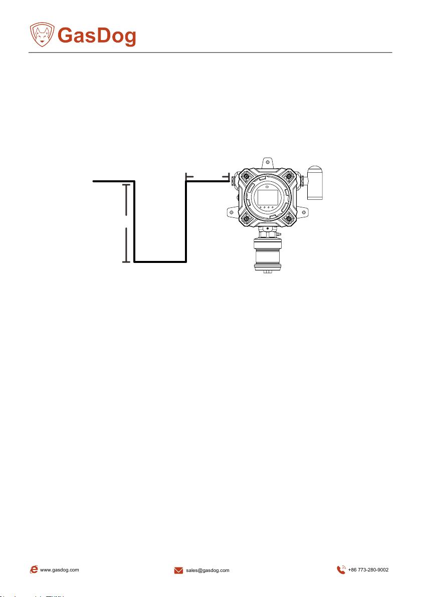
Application example: At the site, the detector detects harmful gas and reaches the alarm
value. The detector screen and indicator lights prompt an alarm, and if an optional alarm light is
installed, there will be an audible and visual alarm. At this time, the normally open end of the
relay closes the circuit, (as shown in the figure below), which can drive the fan for ventilation or
drive the alarm system.
Warning: When the instrument alarms, you must leave the workplace as soon
as possible. Otherwise, serious personal injury or personal injury may be caused.
Please re-calibrate and check the detector afterwards to avoid the expansion of
equipment errors and cause false alarms.
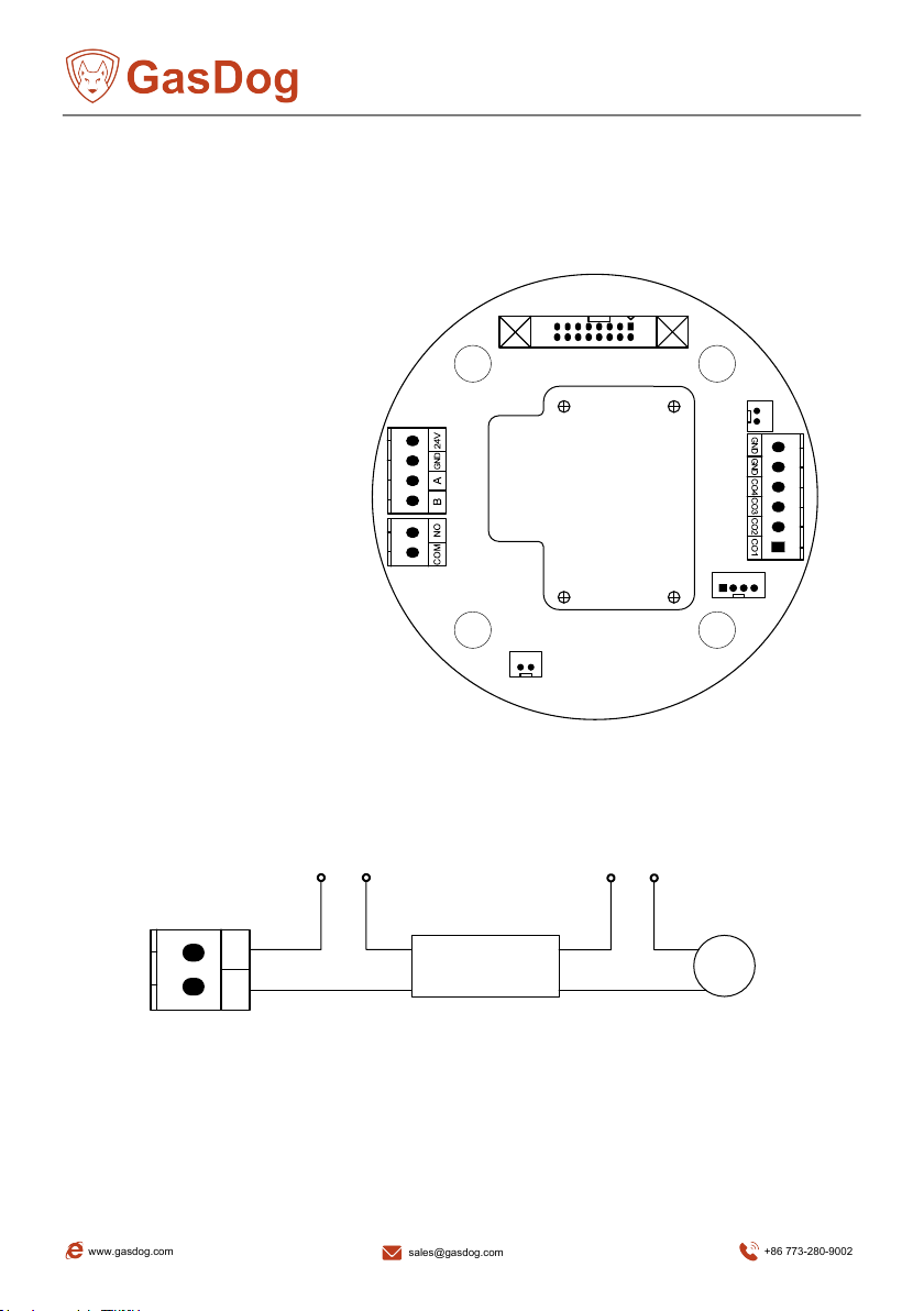
Wiring interface
J1 on left is the relay control interface: COM (common end), NO (normally open end).
J2 terminal on left, the interfaces from top to bottom are: 24V (DC power-positive), GND
(power ground), A (RS485A-positive end), B (RS485B-negative end).
JP5 Alarm light interface
JP2 terminal on right is the 4-20mA
interface
JP3 terminal on right is the
digital probe interface, from top to
bottom are:
GND (power ground), followed
by sensor channels COM4, COM3,
COM2, COM1.
Pump
J1 Relay
Power supply
RS485
Sensor
connection port
Alarm
JP2
JP3
J2
JP6
JP5
JP1
4~20mA
www.gasdog.com +86 773-280-9002
12

Connection diagram of multiple instruments
4-20mA current signal output mode and RS485 digital signal output mode are different in
wiring; the following example power supply connection mode is for reference only, and the
power supply mode can be selected according to the actual situation during installation.
A. 4-20mA current signal output connection mode. (must be grounded together)
GND
A. RS485 digital signal output connection mode 1. (can be independently
grounded)
C. RS485 digital signal output connection mode 2. (can be independently grounded)
Control panel,
DCS or PLC
Channel 2
Channel 1
24V
Channel N
4-20mA
4-20mA
4-20mA
GND
RS485B
RS485A
GND
PC software
RS485-USB
adapter
12N
24V
GND
RS485B
RS485A
GND
24V
GND
12N
12N
Control panel,
DCS or PLC
www.gasdog.com +86 773-280-9002
13

8` Remote controller instruction
Note: When using, please aim at the infrared receiving port above the display screen to
operate. The instrument is equipped with a remote controller with a total of 11 buttons. as
the picture shows.
MENU
PUMP BACK
OK
1. MENU key: enter the menu (in the detection interface).
2. Mute key: Turn off the alarm sound of the instrument (in the detection interface).
3. PUMP key: switch the pump on and off (in the detection interface).
4. BACK key: cancel; return to the previous menu or detection interface,Double-click the
BACK button on the detection interface to switch the unit (only μmol/mol and PPM).
5. OK key: confirm; enter the next level menu.
6. Up key: Move the cursor up.
7. Down key: Move the cursor down.
8. Left key: move the cursor to the left; select the position to modify the data.
9. Right key: move the cursor to the right; choose to modify the data position.
10. Add key: increase the value.
11. Minus key: decrease the value.
Key
MENU
Mute
PUMP
BACK
OK
↑
↓
←
→
+
-
Function
Enter the menu
Turn off the sound
Power on or off the pump
Cancel/Return/Unit Switch
Confirm
Shift Up
Shift Down
Shift left
Shift Up right
Plus
Minus
www.gasdog.com +86 773-280-9002
14
9` Function Description
1 Power On/Off
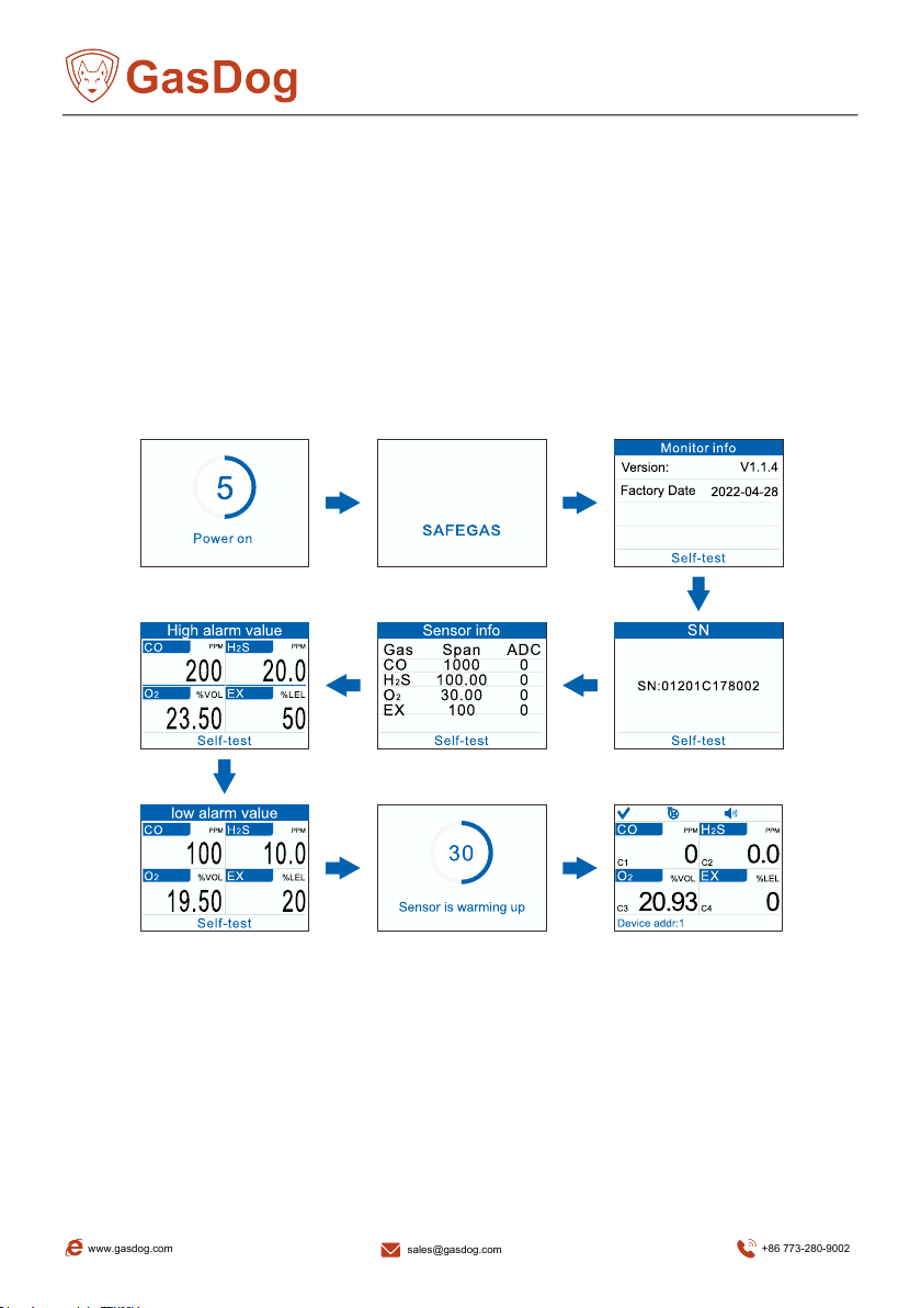
1.1 Power On
1) In the power-off state, check whether the power cord on the left side of the instrument is
in good condition and has no foreign objects.
2) When connect with the power, the instrument power on.
When the instrument power on, it will initially display "Power On" (if it cannot be displayed
normally, the instrument may be faulty, please contact the agent or after-sales service
department at that time), then enter the self-test, and then enter the instrument preheating
countdown.
After the startup is complete, the reading and various function icons will be displayed on the
screen.
1.2 Power Off
In the normal measurement state or when there is power, just disconnect
the power.
www.gasdog.com +86 773-280-9002
15

2 User Interface
2.1 Detection interface description
The detection interface on the instrument displays the sensor type, indication and other
functional status information.
The top are: self-test status (passed "√", failed "×"), air pump (pump running-blue dynamic;
pump stop-gray), alarm (on-blue; off-gray)
1)
Self-test status: blue √ self-test is successful and the device is normal; gray X means the
device is abnormal in self-test, please contact the manufacturer.
2) Air pump status: blue on, gray off.
3) Sound status(Optional): blue on, gray off. It's the optional function. If detector with alarm
light, then have this function.
4) Gas name: The name of the gas type is in the blue box.
5) Gas unit: Small black characters are gas units.
6) Channel number: Corresponding to output 4-20mA interface CO1, CO2, CO3, CO4 (page
12).
7) Concentration reading: The black characters are the gas concentration readings.
8) Address number: detector address
When the following screen appears, please check the device.
Loss of signal: The detector is not connected or has poor contact. After the reconnection is
correct, the interface still appears, please contact the manufacturer.
www.gasdog.com +86 773-280-9002
16
2.2 Main menu interface operation
In the gas detection interface, short press the "MENU" button, the instrument will enter the
main menu interface immediately; press the "BACK" button in the main menu interface to return
to the gas detection interface.
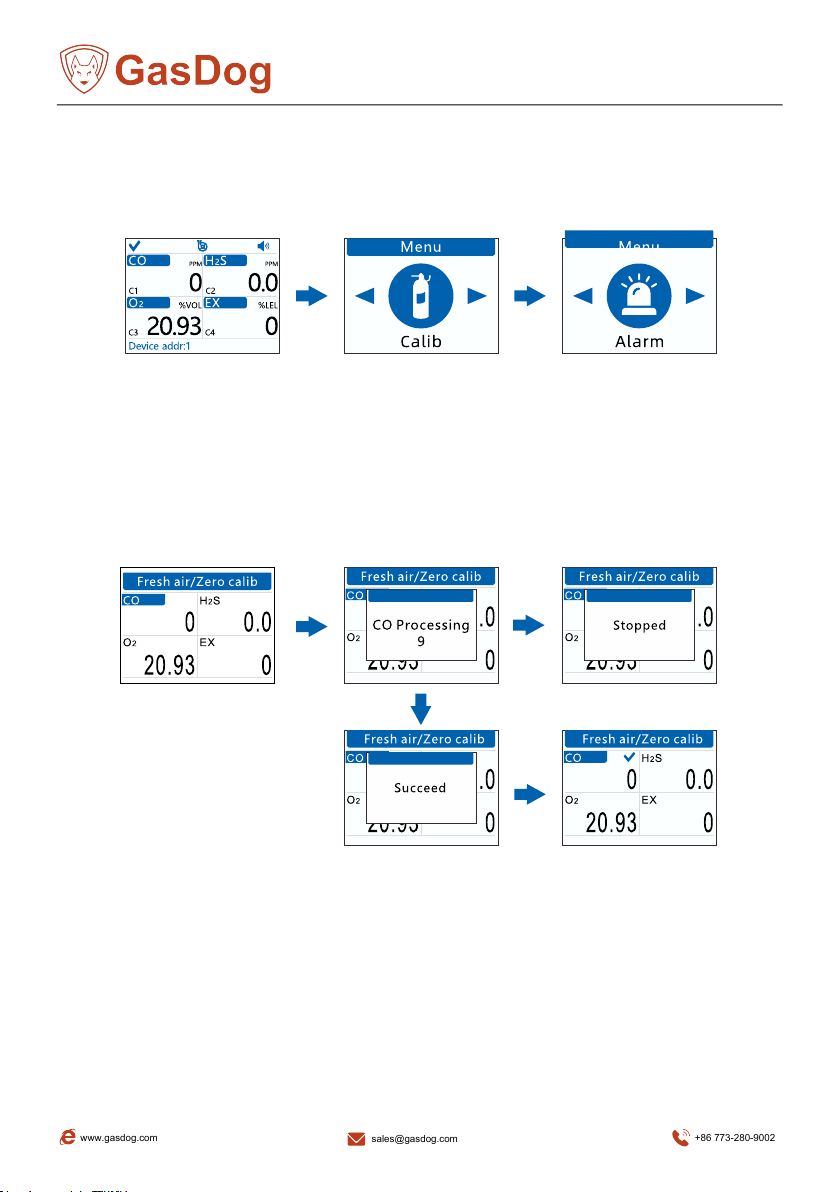
2.3 Calibration
2.3.1 Fresh air/zero
calibration
In the fresh air/zero point calibration interface, press the "←" and "→" keys to select the
sensor to be calibrated, and then press the "OK" key to enter the calibration state, and then
enter the 30-second countdown. During the calibration countdown period, you can press
"BACK" Key to cancel zero calibration..
* In the "fresh air/zero point calibration" interface, you can press the "BACK" key to return to
the previous menu.
Notice:
1. For gases originally existing in the air (such as carbon dioxide, oxygen, nitrogen), the
instrument is calibrated as 450PPM for carbon dioxide; 20.93% VOL for oxygen; 78.1%
VOL for nitrogen.
2. Before do this operation, it is recommended to start up and warm up for 10~20 minutes.
3. When performing this operation, please turn on the instrument and place it in pure air for
3-5 minutes, and wait for the value to stabilize before proceeding, otherwise the displayed
data will be inaccurate.
www.gasdog.com +86 773-280-9002
17
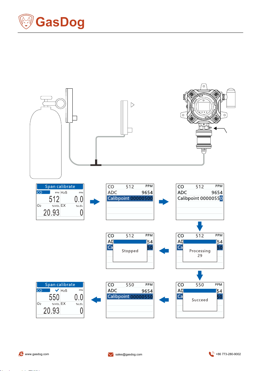
2.3.2 Span Calibration
The pump flow of YT-98H is about 0.6(±0.1)L/min. The instrument must be connected to
the standard gas cylinder through a T-shaped calibration tube (tee joint), and the other end is
connected to the flow meter. During ventilation calibration, ensure that the emptying of the
bypass flow meter is above 100mL/min.
In the span calibration interface, press the "OK" key to enter the span calibration sub-interface.
Calibration
gas
T-tube
PTFE tube
Pressure
reducing
valve
flowmeter
Flowmeter
Emptying
Ensure
normal
exhaust
www.gasdog.com +86 773-280-9002
18

There is an option in the span calibration sub-interface. At the same time, the gas type,
real-time concentration value, unit and ADC value are displayed at the top.
The span calibration process is as follows (the following example assumes that the
calibration gas is 550PPM CO):
After the instrument is turned on and enters the span calibration interface, connect a
calibration gas with a known concentration to the the instrument through a PTFE tube.
According to the actually used calibration gas concentration value (550PPM), use the "↑" and
"↓" keys to move the cursor to select the closest calibration point.
Press the "OK" key to enter the parameter setting mode, use the "←" and "→" keys to move
the cursor to select the pre-modified number, and the "+" and "-" keys to modify the selected
number, and set the value on the right (set fixed value) is modified to be the same as the
calibration gas used.
Open the valve of the calibration gas cylinder, and input the calibration gas into the instrument
at a flow rate of 0.9L/min (ml/min) or more. After the real-time concentration (upper middle)
displayed on the instrument is basically stable (about 1-3 minutes, The stabilization time of
different sensor is different), press the "OK" button, then the instrument enters the 30-second
countdown for calibration, the calibration operation is completed after the screen displays ”
success”.
Notice:
1. During the calibration countdown period, you can press the "BACK" key to terminate
the standard gas calibration.
2. When performing calibration, please confirm that the standard gas pipeline has been
connected. Please perform calibration after the value displayed is stable,
otherwise will cause inaccurate measurement.
3. Setting value: the actual concentration of the calibration gas currently input.
4. When selecting the calibration point, please follow the principle of "zero point <
calibration point≤ range", otherwise the calibration will be failed.
www.gasdog.com +86 773-280-9002
19

2.4 Alarm set
2.4.1 High alarm value, low alarm
value
There are 2 alarm values, high alarm value and low alarm value, take the high reporting limit
as an example. In the alarm setting interface, press the "←" and "→" keys to move the cursor to
select and enter the high alarm limit setting interface.
High alarm value set:
● Press the "OK" key to confirm the input, and then press the "+" and "-" keys to modify
the value.
● Press the "←" and "→" keys to move the cursor.
● After entering the value, press the "OK" key to confirm.
Notice:
1. The high alarm value cannot be lower than the low alarm value.
2. The low alarm value or the high alarm value cannot
be higher than the range.
*Indicator status:
Power: After power on, the green light is on.
Low alarm : no low alarm, light is off; low alarm,
red light is on.
High alarm: no high alarm, light is off; high alarm,
red light is on.
Fault: no fault, no light; self-test fault, orange light
on.
www.gasdog.com +86 773-280-9002
20
Table of contents
Other GasDog Gas Detector manuals


