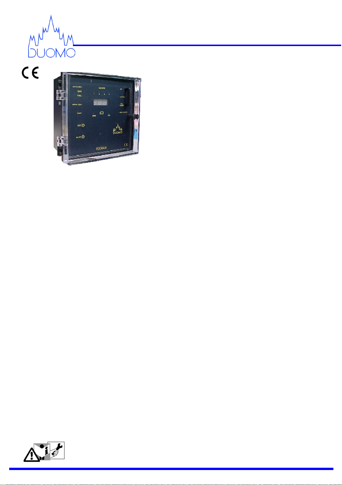
Duomo BX444 User manual

BX444 Gas Detector
Detects Carbon Monoxide,Natural Gas & L.P.G.
230V and 12V DC.
One, two, three or four Zone.
Self Diagnostic
Manual or Automatic Reset
Adjustable Pre-Alarm
Catalytic and Electrochemical Sensors
Audible Alarm
Sensor Fault Alarm
Manual Test Function
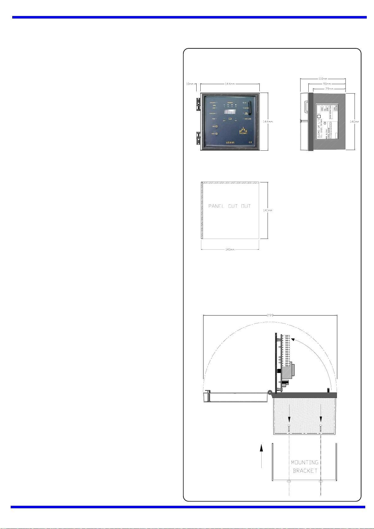
144 x 144 DIN Enclosure
Panel or wall Mounting
1 Year Guarantee
Duomo is recognised within the Gas industry for
providing a comprehensive range of low cost, high
reliability gas detection for many applications. We
have installed and commissioned Natural gas and
carbon monoxide sensors in applications such as
boiler rooms, kitchens, car parks, aircraft hangars,
factories and shopping centres.
Application
The BX444 has been designed to meet all European
Normative proposals for the detection of Natural Gas,
LPGandCarbonMonoxideGasDetectors.TheBX444
is provides protection from gas leakage in areas such
as Boiler Rooms Roof spaces unventilated voids. Car-
bon Monoxide is an invisible, odourless gas which in-
hibits the bodies ability to process Oxygen. The BX444
protects against this in underground or poorly venti-
lated car parks, boiler rooms, vehicle servicing areas
etc. Remote sensors are installed in the areas which
requireconnectedtoremotesensorslocatedinthepro-
tected area. The 144 x 144 enclosure is wall or panel
mounting.
Operation
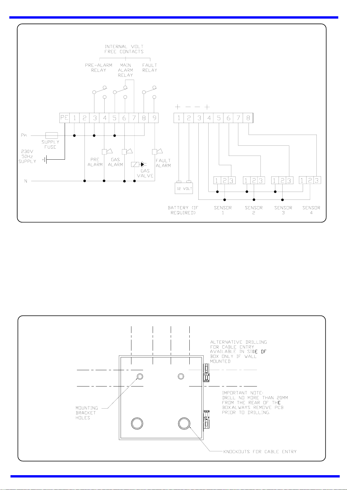
If the remote sensors sense the presence of Gas the
detector operates a pre-alarm relay - used for remote
sirens or extract fans; if the level of gas continues to
rise then the main alarm relay is activated to, either in
the case of explosive gases, break the electrical sup-
plyto the Safety Shut OffValveorforCOsound a Gen-
eral Alarm to allow evacuation of the area.
Features
The Pre-Alarmcanbeadjusted, inthecaseofNatu-
ral Gas or LPG, from 8% to 15% of the Lower Ex-
plosive Level (LEL). For Carbon Monoxide, it can
be adjusted from 120ppm to 250ppm. The Main
Alarm thresholds are not adjustable and are fixed at
20% LEL for explosive gas and 300 ppm for Car-
bon Monoxide. The detectors can be set for either
toxic or explosive Gas. Or both.
It is possible to set one zone for explosive gas such
as Natural Gas or LPG and another for toxic gas for
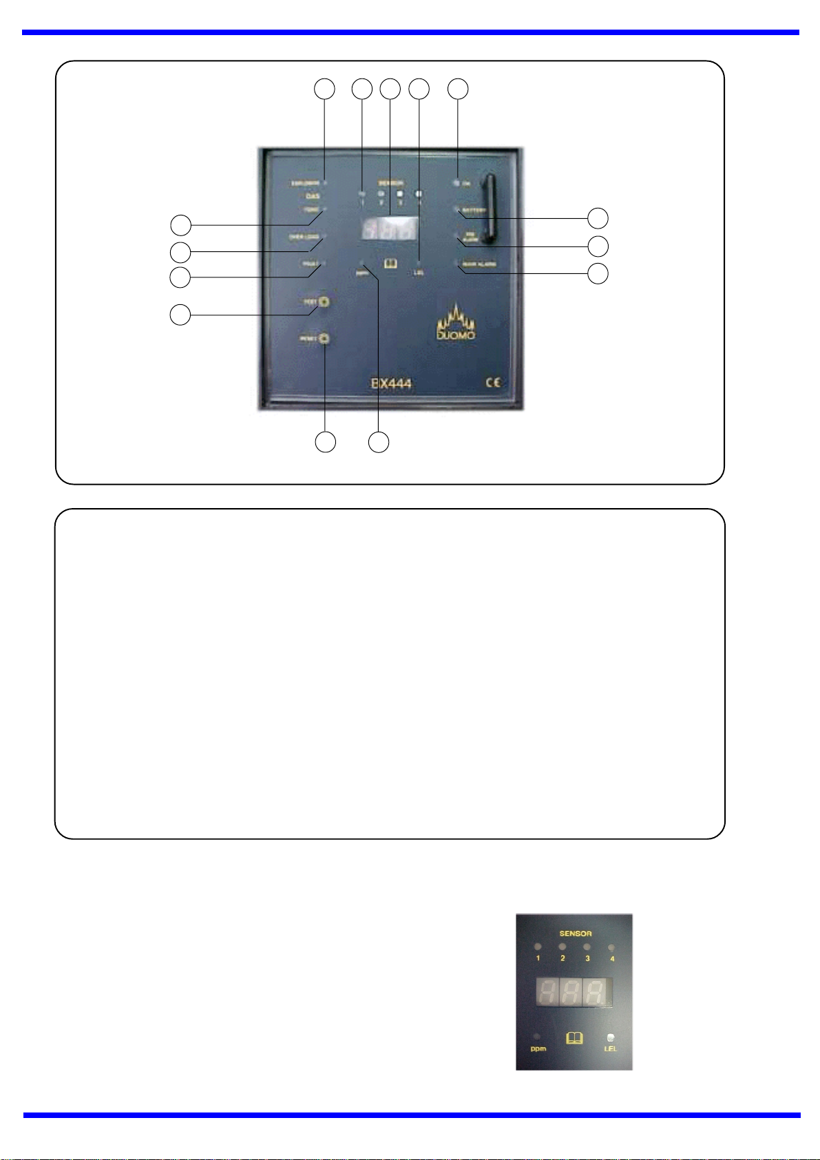
example Carbon Monoxide. An LED display on the
fascia indicates the levels of detected gas in either:-
parts per million (ppm) or percentage of Lower Ex-
plosive Level (%LEL). Lights above the display indi-
cate which sensor the Numeric LED display refers
to. It is possible to use the detector as a one, two,
three or four zone by enabling or disabling each
channel.
A ‘TEST’ button on the facia, when pressed, checks
the complete function of the BX444 and sensors. A
permanent diagnosticcheckismadeofsensorfunc-
tion. If any sensors should become faulty or be con-
nected incorrectly the ‘FAULT’ light will illuminate
and the detector will fail safe.
CAUTION!
Carefully read the following instructions prior to installation of this device. Always
keep this pamphlet for future reference. Ensure that the gas detection system is
wired correctly, the appropriate sensor is installed and used only for the purpose
which it is intended.
BX444 Four Zone
Gas Detector

Key
1EXPLOSIVE - Indicates when the natural gas & LPG function is selected.
2SENSOR LED’s - These show which sensor the displayed levels refer to.
3 Numeric LED display - This shows the concentration of detected gas in either ppm or as %LEL.
4LEL - This shows that the numeric display refers to % LEL .
5ON - indicates external power source is healthy.
6BATTERY - 12V battery connected rather than mains supply.
7PRE-ALARM - Indicates when the gas level has reached the selected pre-alarm threshold.
8MAIN ALARM- Indicates when the concentration of gas reaches 20% LEL Methane or 300ppm of
Carbon Monoxide.
9PPM - The LED numeric display refers to parts per million of the detected gas.
10 RESET - Press to reset alarm. This resets the detector memory.
11 TEST- Push button. Provides full function test of detector.
12 FAULT - Flashes when the sensor is either faulty, connected incorrectly or not selected.
13 OVERLOAD - Power consumption of the BX444 is too high.
14 TOXIC - Indicates that the Carbon Monoxide function is selected.
BX444 Facia
6
7
8
9
10
11
12
13
14
1 2 3 4 5
Digital Display
This shows the quantity of gas detected by each sensor.
The display can be configured to display values in parts
per million (ppm) percentage of the lower explosive level
(LEL). As the blue lights marked 1 to 4 illuminate, the
value shown on the display corresponds to the gas levels
detected by sensors 1 to 4 respectively. During the Reset
procedure the explosive, toxic, sensor 1,2,3 and 4 lights
will flash. The display will scroll through numbers up to
990 for each zone and then will stabilize at 000.

Installation
Mounting the detector
The BX444 can be wall mounted or panel
mounted. See fig.(2) for panel cutout dimen-
sions . When panel mounted the support
bracket supplied loose should be fitted as shown
in fig.(3)
Cable gland entries are provided in the form of 2
pre-moulded 20mm ‘knockouts’ in the back of
the BX444 box. Alternatively it is possible to
carefully drill into the sides of the box. Note: See
fig.(4) for suitable drill positions. Always ensure
that the printed circuit board will clear the cable
gland when closed. It is recommended that the
PCB facia assembly is removed prior to drilling
for gland entry.
Positioning Sensors
The SG590 (Methane) and CO100 (Carbon
Monoxide) Sensors should be mounted in
accordance with the following considerations.
Do not position next to burners, heaters or
ovens where temperatures above the room
ambient may be experienced. It is, if possible,
better to mount the sensors on the opposite
wall. This is, of course, dependant on the size of
the protected area.
Natural Gas is lighter than air and therefore will
obviously rise, therefore the SG590 (methane)
sensor should be mounted 300mm from the
ceiling of the protected area.
For LPG (Propane and butane) the SG590 LPG
must be connected. LPG is heavier than air so
the sensor must be located 300mm from floor
level.
Carbon Monoxide has specific gravity of 0.97
and is therefore slightly lighter than air. However
for positioning purposes at the concentrations of
CO relating to the detector alarm thresholds the
resultant combination of CO and air will neither
rise or fall. The best position to mount the
C0100 is 1.6m above ground level.
If you require assistance regarding locating sen-
sors please call our Droitwich Factory on (01905)
797989 alternatively fax a drawing of your appli-
cation to (01905) 774296 and we will advise ac-
cordingly.
Fig.2
Fig.3
Fig.1

Typical External Wiring Diagram for BX444
Electrical Connection
The sensor can be located up to 100m from the gas
detector. Cable size should be 1mm CSA. If the
sensor cables are run separately in specific conduit it
is not essential to use screened cable but if the cables
are routed through conduit or trunking containing other
wiring the use of screened cable is advisable. The
wiring should be performed by a qualified person in
accordance with current regulations.
Fig.4
Cable Entry Points
The plug in terminal rail makes installation easy and
quick.
Note: It is essential that enough length is left in the
cable loom to allow the facia to be hinged open as
shown in fig (3). The wiring must be checked prior to
powering up the system.

Configuring the detector
How Many zones....?
The BX444 can be configured to provide one, two,
three or four zone protection. Sensors are enabled
and disabled by switching the zone select switches on
and off. To disable a zone move
the switch to the ON position. The
switches shown are in the zone
enabled position. When you have
made the switch change press the
reset on the BX444 fascia.
Gas or Carbon Monoxide...?
If the gas to be sensed is Explosive you must first
ensure that the correct sensor is connected to the
system. For instance, for Natural Gas SG590. Each
pair of switches shown
below corresponds to a
sensor. From left to
right, 1 to 4. To select
the Explosive Indication
on the fascia for a
particular sensor move
switch 1 to the ON
position and switch 2 to the off position. If another
zone is being used to sense carbon monoxide, again
ensure that the correct sensor is connected to that
zone for example CO200.
Pre-alarm adjustment
ppm/LEL & auto/ manual
reset selectors
Zone selectors
Explosive or Toxic
selectors
Terminal block 1
Terminal block 2
Continuous/pulsed main alarm
jumper
Printed Circuit board Layout
Select Toxic indication by moving switch 2 to the ON
position and switch 1 to the off position. In the above
picture this shows zone 1 Toxic, zone 2 explosive, zone 3
toxic, zone 4 explosive.
Pre-Alarm Sensitivity Adjustment
The Pre-Alarm can be adjusted, in the
case of Natural Gas or LPG, from 8% to
15% of the Lower Explosive Level (LEL).
For Carbon Monoxide, it can be adjusted
from 120ppm to 250ppm. Adjustment is
made using the pre-alarm potentiometer
marked PT1. To increase the sensitivity
turn the potentiometer away from the
central point either left or right. i.e. Central Position is 15%
LEL. Left or right 8% LEL.
Setting Main Alarm Memory function
The Main Alarm thresholds are not adjustable and are
fixed at 20% LEL for Natural Gas or LPG and 300 ppm
for Carbon Monoxide. The main alarm can be configured
to provide either a latching or an auto reset relay
actuation. For example to turn off gas valves or to boost
ventilation in car parks or areas containing carbon
monoxide. Should gas be sensed in boiler rooms
laboratories etc. the gas valve supplying the room will be
turned off by the detector. This must only be manually
reset following an alarm. However if the BX444 is being
used to control the levels of carbon monoxide in car parks
as long as the ventilation is boosted and the levels of
Carbon Monoxide drop there is no requirement to
maintain the alarm so the unit can be allowed to
automaticallyreset.

INCASE OF AN ALARM
1PUT OUT ANY NAKED FLAMES
2CLOSE THE MANUAL GAS VALVE SUPPLYING THE PROTECTED AREA
3DONOT TURN ANY ELECTRICAL DEVICES ON OR OFF.
4O
PEN ALL WINDOWS AND DOORS TO INCREASE VENTILATION
5IFTHE ALARM STOPS IT IS NECESSARY TO FIND THE CAUSE OF THE ALARM BEFORE ATTEMPTING
TO RESET THE DETECTOR. THIS MUST BE CARRIED OUT BY ARESPONSIBLE, QUALIFIED PERSON.
6I
FTHE ALARM CONTINUES AND THE CAUSE IS NOT EVIDENT OR POSSIBLE TO ELIMINATE, LEAVE
THE ROOM AND CONTACT YOUR GAS PROVIDERS’ EMERGENCY LINE. THEY WILL ADVISE
ACCORDINGLY.
The installation of this gas detector does not release the user from observing all the regulations concerning
the characteristics , installation and the use of gas appliances; the ventilation of the environment and the
elimination of combustion products in accordance with local recommendations, regulations and byelaws.
For any damage caused to people, property or animals resulting from incorrect connection, installation or
application of this gas detector Duomo will not be held responsible or liable.
This Gas detector is a safety device and therefore should only be maintained and installed by qualified
persons. To ensure correct function after installation Duomo provide a commissioning service using cali-
brated test gases. For the service call 01905 797989.
Warning
To make the main alarm a latching
operation, move switch 1 shown to
the off position. (This is the factory
setting).
For an auto-reset function move
switch 1 to the ON position. It is
then necessary for the BX444 to be
reset in order for this change to take effect.
Note: This setting should only be made by a qualified
technician.
The BX444 can also be set to give a pulsed or continuous
main alarm function. This is mainly used to extend battery
back up time. For example, if a manual reset solenoid
valve is used to shut off the gas the 12V supply does not
need to be continuously applied. The valve will only
require a trigger
pulse to close it. This
setting is made by
moving the jumper
shown below to the I
position. The factory
setting is
continuous. It is
again necessary to
press the reset to
implement this
change.
Setting Main Alarm Memory function

Faults - symptoms and solutions
When power is applied to the unit no lights or displays are lit.
Check the power supply.
Check that the terminal plug on the reverse of the pcb is wired properly.
Check that the terminal plug is pushed securely into the socket.
Fault light is illuminated and the BX444 is in alarm.
Has the correct number of sensors been selected on the p.c.b. See configuring the operation of the BX444.
Is the green Light illuminated on the sensor?
Check sensor connections.
Is the connector plug in the sensor secure?
Check that there is no interruption to the cable supply to the sensor.
The alarm function isn’t latching. When gas levels indicated drop below the main alarm threshold the main
relay resets.
Check the position of the alarm function Switch. There are two modes. i) Auto reset ii) Latch with manual Reset.
When you have selected the correct memory function you must press the reset button so that this change takes
effect. The main alarm relay changes over the volt-free relay and then with the Main Alarm light still on the relay re-
energises.
Check the position of the Jumper link JP1. This is located between the two terminal plugs. When in the ‘C’ position
the relay will stay on, either until the level of detected gas drops if set for auto reset or until the level of gas drops
and the BX444 is manually reset. If the jumper is set to ‘I’position the relay will de-energise momentarily then
automatically return to the on position. This function is used when the detector is connected to a manual reset valve
which only needs a trigger pulse to close it. This also extends battery backup time as solenoid valves do not need to
be constantly powered. Check local regulations recommendations regarding manual reset gas valves and their
control.

Unit 5 Judge Court, North Bank, Berryhill Industrial Est. Droitwich, Worcestershire, England, UK, WR9-9AU
2”BSP G621 with lockable
bypass
GS100 Single Zone
Gas Detector. 230V
AC or 12 VDC
Supply.
SG500 Single Zone
Gas Sensor. IP30
SG580 EX Certified
Gas Sensor for
Natural Gas and
LPG.
Gas Solenoid Valves
from1/2”BSPto4”
Flanged EN161
approved.
GS150K Single Zone
Gas Detector . 230V
AC or 12 VDC
Supply.
GS300 Three Zone
Gas Detector. 230V
AC or 12 VDC
Supply.
SG590 Catalytic
Nat Gas or LPG
Gas Sensor. IP55.
12 VDC Supply.
4-20mA output.
CO100 Catalytic
Carbon Monoxide
Gas Sensor. IP55.
12 VDC Supply.
4-20mA output.
CO200 and 230 Catalytic
Carbon Monoxide Gas
Sensor with digital display
and Change over Relay.
30ppm CO. IP55.
Product
Overview
Gas
Detection
CO200A CO Sensor
for Car Parks. 12 or
24VDC supply
4-20mA Output. IP55
Gas
Safestart
Guarantee
This device is guaranteed for a period of 12 months from the date of purchase.
Conditions. Substitution free of charge of any component recognized as being faulty from production. The
unit must be delivered to the resaler or directly to Duomo.
KS21 Keystart Control Panel
The Duomo Gas Safestart is...
aweepbypass assemblywhich provesthat therearenogas
taps open or serious leakages in gas pipe-work which relies
on manually operated gas valves as the only means of
isolation.
Fact:
Manual gas valves do get left on and will be operated by
unauthorised individuals.
for Kitchens and Laboratories
Table of contents
Other Duomo Gas Detector manuals
Popular Gas Detector manuals by other brands

Dräger
Dräger VarioGard Instructions for use

BEINAT
BEINAT SGM595-H2CH Installation and user guide

Thermo Scientific
Thermo Scientific GLD PRO user manual

PNI
PNI SAFE HOUSE 200 user manual

International Gas Detectors
International Gas Detectors TOC-635 Installer's guide

GASTRON
GASTRON GTD-1000Tx instruction manual