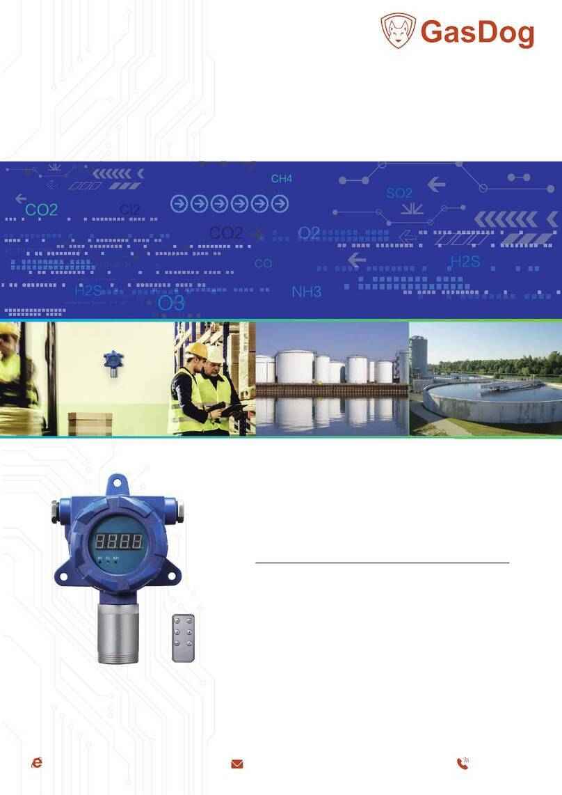
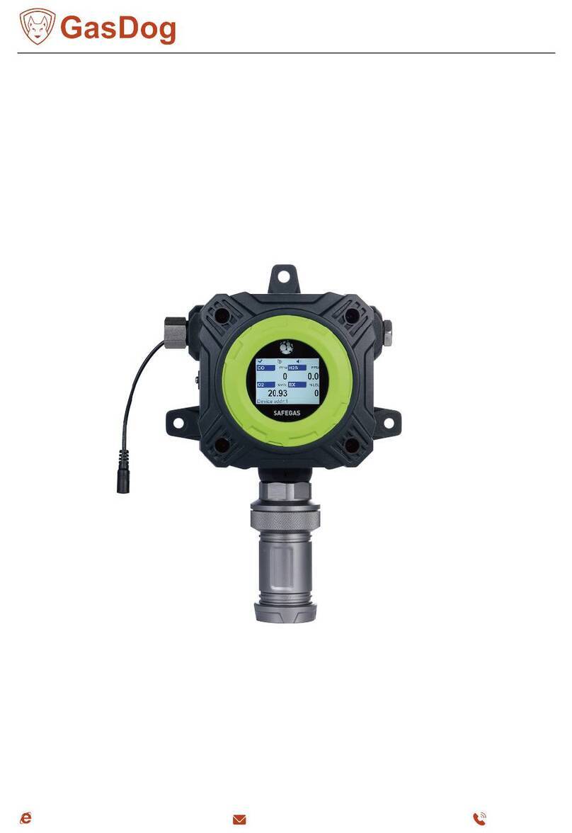
GasDog GD300 Series User manual

Online Fixed Gas
Detector
GD300:XX
Instruction Manual
Notice to Reader
Please read this instruction manual before using the detector
1

1 Read before operation
1)All operators who operate and test the instruments must read the instruction manual carefully
before operation. The instruments can only work properly when they are operated in accordance with
the company's instructions for use.
2) The use of the instruments must be operated in accordance with the procedures determined in the
manual.
3) The maintenance of the instrument and the replacement of parts are handled by our company or
local maintenance stations.
4. If the user does not follow the above instructions to repair or replace parts without authorization, the
operator is responsible for the reliability of the instrument, and our company is no
longer responsible for the warranty.
5) The instrument should be calibrated at least once a year (it is recommended to calibrate every 3-6
months); the explosion-proof disc of the sensor should be cleaned regularly (purging with low-pressure
compressed air) according to the applicable scene, otherwise dust and impurities will block the protective
hole, which will affect the detection sensitivity.
6) The use of the instruments should also comply with the laws and regulations of relevant domestic
departments and the management of instruments in the factory.
Warranty
The instruments produced by our company have a 12-month warranty period and lifetime
maintenance. The warranty period starts from the date of delivery. During use, the user should follow
the instructions. The damage to the instrument due to improper use by the user or poor working
environment is not covered by the warranty. The user should keep the factory certificate properly, and
the warranty period is subject to the date on the certificate. Please pay attention to attach the factory
certificate when returning for repair.
2

Contents
------------------------------------------------------ 3
---------------------------------------------------------- 5
----------------------------------------------------------- 5
----------------------------------------------------------- 8
----------------------------------------------------------- 11
-----------------------------------------------14
------------------------------------------------16
----------------------------------------------------16
-------------------------------------------------------------------------17
1 Read before operation
2 Structure diagram
3 Installation method
4 Wiring Instructions
5 Calibration method
6 Remote controller operation
7 Common faults and repairs
8 Instrument configuration
9 Appendix
3

2 Structure diagram
1,Power supply and Signal line entrance and exit
2,Circuit board
3,Terminals
4,Sound and light alarm interface
5,Sensor head
6,Sensor head interface
7,Connect the claw socket to the mainboard
3 Installation method
Select the installation location
The installation position is very important to achieve the best detection effect.
When determining the location, it is necessary to comprehensively consider the following factors:
such as the density of the gas leak point, the specific gravity of the gas to be measured, the influence of
the surrounding buildings, the age of the production equipment, the wind direction and the weather
conditions all year round, etc. The location of doors and windows should also be considered indoors.
The following suggestions are for users' reference:
A. Appropriate distance should be maintained between the instrument and the possible leakage point of
the gas to be tested. If it is too close, the reaction speed will be very fast, but if the leakage is frequent, it will
cause too many alarms, or the long-term alarm state will make people paralyzed; if it is too far, the reaction
speed will be too slow, or even no response.
B. The instrument should be installed in the downwind direction of the leakage point.
C. When installing indoors, if the leakage source is outdoors, the instrument should be installed at
the air inlet.
D. The installation height should be determined according to the specific gravity of the measured gas and
air.
E. The number of instruments should be selected according to the possible leakage points of the gas to
be measured, the frequency of personnel appearance and the residence time, so as to achieve the best
detection effect.
F. If the equipment is outdated, it can be considered to increase the measured points.
G. The instrument should be prevented from being radiated by a high temperature heat source. Too
high or too low temperature will affect the use effect and lifetime of the sensors.
≥30CM
≤2CM
Cable
Figure H
IR ALAH
8.8.8.8
H. The instrument should be protected
from damp and rainwater inflow, which will
affect the internal circuit board.
The wiring recommendations are shown
in the diagram below.
Ground
connection port
5
6
123
4
7
4

四、技术性能及参数
1、技术性能
检测误差:≤±5%FS或±10%(视具体气体类型而定)
工作温度:-20~50℃
工作湿度:0~95%RH
传感器工作原理:氧气及有毒气体为电化学式,可燃性气体为催化燃烧
式。
传感器寿命:视具体检测环境而定
2、其它技术参数
检测方式:扩散式
工作方式:固定式二十四小时连续工作
工作电压:12~24V,DC
功 率:<4W
输出信号:三线制4~20mA标准信号、RS485信号
继 电 器:标配一个(可选配扩展一个),
用户自行外接其他负载需增加单独固态继电器进行隔离
外型结构:压铸铝壳体
外型尺寸:206X179X90mm(无安装支架)、
206X179X110mm(带支架)
重 量:无安装支架~1.2kg,带支架~1.6kg
连接距离:<1000m
防护等级:IP65
管道螺纹尺寸:M45XP2.0
安装方式:壁挂式、管道式
防爆形式:隔爆型
防爆等级:Ex d IIC T6 Gb
进 线 口:六角型锁紧螺母
Select the installation type
1) Wall-mounted type: This type of installation is usually selected for normal indoor inspection.
According to the size of the outer hole of the mounting bracket (optional), fix two or four 6mm expansion
bolts on the wall, and fix the bracket and the detector with screws, nuts, spring washers and flat washers.
Then use 6x30mm nuts and spring washers to fix the expansion bolts on the wall, see the picture
below.
Note: The installation location must be well grounded or insulated. Leakage of electricity may cause the
detector to work abnormally.
2)
Pipe-mounted type: The installation thread size of the instrument is M45*P2.0. During the
installation process, hold the detector with both hands so that the sensor is parallel to the installation
thread, align the screw mouth, rotate the detector clockwise, and then install the detector on the target
position. In order to prevent air leakage at the threaded interface, suitable raw tape can be wrapped
around the threads on the sensor head before installation.
Note: The pipe-mounted type requires that the inside of the pipeline is normal temperature and
pressure (temperature -20~50℃, pressure 0.1mPa) and humidity ≤95%RH. If the above conditions are
not met and this installation method is required, please contact the manufacturer for a solution.
5

Instrument Dimensions and Mounting Hole Map
●Apperance and installation hole map
118.00
φ8.00
140.00
φ8.00 φ8.00
102.30
206.00
89.00
●Apperance and installation hole map of gas detector with alarm light
φ8.00
179.00
102.00
φ8.00φ8.00
118.00
206.00
89.00
6

4 Wiring Instructions
4.1, Cable requirements:
Power lines and 4-20mA signal lines need to use shielded cables, and RS485 lines are recommended to
use twisted pairs. When using RS485 communication to connect with the controller (Under normal
conditions) , the RS485 signal transmission distance of our detector can reach more than 1000 meters.
When the signal interference is large or the transmission distance is longer, it is recommended to add an
RS485 repeater, a 120Ω/0.5W matching resistor should be connected in parallel between the A and B lines
of the farthest detector.
The power supply voltage of this series of detectors is 12~24VDC. Due to the voltage drop caused by the
impedance of the cable itself, it should be ensured that the minimum supply voltage of all detectors is
12VDC.
When the detector is powered by the controller, the power supply voltage of the controller of our
company is 24VDC. To ensure that the minimum input voltage of the detector is 12VDC, the circuit
voltage drop must be less than or equal to 12VDC, as shown in the figure below.
Maximum Loop Impedance: Rloop = (VController – VDetector(min)) / IDetector Calculated
according to the above formula.
The maximum current of combustible gas detector is 250mA, and the maximum loop resistance is
48Ω;
The maximum current of the toxic gas detector is 100mA, and the maximum loop resistance is 120Ω.
The cable cross-sectional area and the farthest transmission distance are shown in the table below
(when connected to our controller). Make sure that the actual installed cable length is shorter than the
calculated maximum cable transmission distance.
4-20mA
Maximum Loop Resistance
V Controller=24VDC V Controller=12VDC Gas detector
Controller
0VDC 0VDC
1
2
33
2
1
RL
Cross-sectional area of cable core (mm) 0.75 1.00 1.50 2.50
Resistance (ohm/km copper wire) 24.7 18.5 12.3 7.4
The longest cable distance (m)
(loop length/2)
Combustible gas 1000 1250 2000 3200
Toxic gas 2400 3200 5000 8000
Note: The above transmission distance is calculated based on the cable core with a resistivity of
1.85×10ˉ Ω·mm. If a cable of the same wire diameter with a smaller resistivity than this is used, the
transmission distance can be longer; if a cable of the same wire diameter with a higher resistivity than this is
used, the transmission distance will be shortened. The loop length indicates the total length of the positive
and negative wires of the power supply, and the actual length of the cable is equal to half of the loop length.
7

Refer to the following formula for the maximum number of detectors allowed on a single cable: N=Im/
lc=((U-12)/R)/Ic=((U-12)/(ρ×L/S))/Ic
N: Maximum number of detectors
Im: the maximum current passing through the wire(A)
Ic: the average current of a single detector at the lowest starting voltage(A)
U: controller output voltage (our controller is 24V)
R: internal resistance on the cable(Ω)
ρ: core resistivity (copper: 1.85×10ˉ Ω·mm)
L: cable length (the total length of the positive and negative lines of the power supply, if the length
of a single line is 100m, the total length of the two lines is 200m)
S: core cross-sectional area(mm)
When the detector uses our controller to supply power, taking the material as copper (the resistivity is
1.85×10ˉ Ω·mm) as an example, the maximum number of detectors allowed for a single cable can refer to
the following table:
When the detector is not powered by the controller (that is, powered by an independent power supply),
the 4-20mA transmission distance is determined by the load resistance, which includes the output resistance
of the control system (controller, DCS or PLC) and the internal resistance of the cable.
Cable distance (m) 100 200 500 1000
The maximum allowable number of
detectors when using 0.75mm wire
diameter
Toxic gas(100mA@12V) 24 12 4 2
Combustible gas(250mA@12V) 10 5 2 1
The maximum allowable number of
detectors when using 1.0mm wire
diameter
Toxic gas (100mA@12V) 32 16 6 3
Combustible gas (250mA@12V) 12 6 2 1
The maximum allowable number of
detectors when using 1.5mm wire
diameter
Toxic gas (100mA@12V) 48 24 8 4
Combustible gas (250mA@12V) 20 10 4 2
The maximum allowable number of
detectors when using 2.5mm wire
diameter
Toxic gas (100mA@12V) 80 40 15 7
Combustible gas (250mA@12V) 30 15 6 3
The maximum transmission distance refers to the following formula:
L=(R-Rc)/(ρ/S)
L: Maximum transmission distance(m)
R: Maximum load resistance(Ω) (500Ω when powered by 24V, including control system input
resistance and cable internal resistance)
Rc: input resistance of the control system (the input resistance of our controller is 50Ω) ρ:
core resistivity (copper: 1.85×10ˉ Ω·mm)
S: core cross-sectional area(mm)
8

4.2 Wiring Instructions
1: Cable requirements: use shielded cables, the wire diameter is about 0.75mm, and the copper wires at
the wiring must be tightened without burrs;
2: Different instruments, the wiring methods are different:
A. For instruments with lead wires, the following are the meanings of each connection wire (for
reference only):
Red wire: Power positive input (12 to 24V)
Black wire: power ground wire
Yellow wire: 4~20mA output or RS485A
Green wire: RS485B
B. For instruments without lead wires, the user needs to open the instrument shell and connect wires to
the inside terminals. The following figure is the description of each terminal:
Warning: The wiring work must be performed by professionals, otherwise it may cause electric
shock or damage to the instrument.
J1
24V
GND
4-20mA
GND
RS485A
RS485B
Power
Signal output
Low Alarm
Relay High Alarm
Relay
J2
Motherboard connector JP1
J3
Alarm
Digital probe port
Digital probe portDigital probe port
S1
Note: Do not connect wires with power on at any time.
NO:Normally open
COM:Common
24V:24+,positive
GND:24-,negative
4~20mA:4~20mA analog
signal
Wiring diagram
(Optional)
COM
NO
COM
NO
* High alarm relay (Optional) .
9

5 Calibration method
In order to ensure the measurement accuracy, the instrument should be calibrated regularly and
strictly recorded during use.
Calibration equipments:
One bottle of calibration gas with known concentration (Note: The instrument defaults to full scale. In
principle, the selected calibration gas concentration should be greater than 50% of the range and less than
the range.);
Pressure reducing valve;
flow meter 0~1000ml/min;
PTFE tube;
Calibration cap, etc.
Note: When the instrument leaves the factory, the alarm settings of the detector and the panel are
adjusted to the factory default values, and the user can adjust it through the remote controller according to
the situation.
Zero calibration
Make sure the instrument is in clean air environmrnt (do not do this in a non-clean air environment).
Note: After the zero point calibration, the instrument reading will automatically return to zero
(oxygen 20.93% VOL, nitrogen 78.1% VOL, carbon dioxide 450ppm).
Power on when ready.
External load application (low alarm for reference)
24V DC
SSR
(AC/DC)
220V/10A
External load
M
+-+-
220V
(AC/DC)
Low Alarm
Relay High Alarm
Relay
J2
COM
NO
Solid state relay
*High alarm relay (Optional) .
10

The zero calibration steps are as follows:
1: Press the "MENU" key on the remote controller, then
instrument displays F-01.
2: Press "+" key or "-" key to adjust to F-04.
3: Press the "OK" key to display the current gas concentration
reading. Wait until the instrument value is stabilize, press the "OK" key
again, then detector reading will display "PASS", indicating that the
calibration is successful.
IR ALAH
IR ALAH
IR ALAH
4: If the zero calibration is successful, it will automatically return to
the detection interface.
IR ALAH
Span calibration
Connect the calibration gas cylinder of known concentration to the calibration cap (Optional) of the
instrument(as shown in the figure below) through PTFE pipe.
This operation is mainly divided into two steps: [Set Calibration Point] and [Span Calibration].
Note: After the calibration, please remove the calibration cap. Do not install the calibration cap
on the detector during testing.
PRV
PTFE PIPE
Empty
Gas
detector
Standard gas
Flowmeter
Calibration
cap
11

●Set the calibration point
Make sure the detector is connected correctly, power on until the
output of the detector is stable.
1. Press the "MENU" key on the remote controller, the detectorr
displays F-01.
2. Press the "+" key or the "-" key to adjust to F-07.
3.
Press the "OK" key to enter the gas concentration value display interface. The value can be
modified by the "+" and "-" keys to make the value consistent with the calibration gas concentration .
Press the "OK" key to display "PASS" briefly.
IR ALAH
IR ALAH
IR ALAH IR ALAH
IR ALAH
IR ALAH
2.
Press the "+" key to display F-08,
●Span calibration
1.
Press the "BACK" key to exit, the detector will display F-07.
IR ALAH
3.
Press the "OK" key again to enter the function interface. After adjusting the "0" displayed on the
interface to “1 " by the "+" key, press the "OK" key again to display the current detection reading.
IR ALAH
12

4.
At this time, pass in the calibration gas at 300±20ml/min. When
the value of the instrument is stable, press the "OK" key. The instrument
will be automatically calibrated and display "PASS" for a short time. At
this time, the measured concentration value is consistent with the value
set in "F-07" (concentration value of calibration gas). IR ALAH
Note: Pass the calibration gas into the detector. After the output is
stable, adjust and correct the display value of the detector to be the
same as the calibration gas value, and then cut off the gas. Observe
whether it can return to the zero point (in a pure air environment) or
the starting point, and then repeat it again, and the calibration can be IR ALAH
completed with a small difference between the two values (within the
basic error range). If there is a big difference, repeat the above method to calibrate until the calibration
specification is met (the detector is usually adjusted to "20.93% VOL" for oxygen in the air environment, and
the detector is usually adjusted to "78.10% VOL" for nitrogen in the air environment).
Remote controller key function
OK
BACK
MENU RESET
6 Remote controller operation
1: Press the MENU key once to enter the F-01 address code setting menu, press the "OK" key to enter
the modification, press the "+" and "-" keys to modify the instrument address code, and press the "OK" key to
save after the modification is completed. Press the "BACK" key to cancel.
2: Press the "+" key to enter F-02 to enter the low alarm point setting menu, and press the "OK" key to
enter the modification. Press the "+" or "-" key to modify the low alarm value of the instrument. After the
modification is completed, press the "OK" key to save, and press the "BACK" key to cancel.
3: Continue to press the "+" key to enter F-03 to enter the high alarm point setting menu, and press the
"OK" key to enter the modification. Press the "+" and "-" keys to modify the high alarm value of the
instrument. After the modification is completed, press the "OK" key to save, and press the "BACK" key to
cancel.
4: In the parameter setting state, if the remote controller is not operated for 10 seconds, the
instrument will automatically return to the gas detection state, and the parameters being modified
(without pressing the "OK" key to confirm the operation) will not be saved in the EEPROM. The
parameters used are still the previous values when restarted again.
Key Function
MENU Enter the parameter setting state from the
detection state
RESET Cancel the alarm state
+ Displayed parameter increase 1
- Displayed parameter minus 1
OK Confirm the operation
BACK Cancel operation/return
13

F-0X function table
Note: F-06 and below operations do not need to be operated under normal circumstances, and only
professionals can operate when necessary. F-11 to F-19 are reserved functions, please consult the
manufacturer for details.
F-01 address settings RS485 communication address modification
F-02 low alarm value setting The setting value cannot exceed the high alarm value
F-03 High alarm value setting
F-04 Zero calibration
The setting value cannot be lower than the low alarm value
Calibration after stable reading in clean environment
F-05 4MA current trimming
C-04, 4mA output (modifiable)
C-08, 8mA output (cannot be modified)
C-12, 12mA output (cannot be modified)
C-16, 16mA output (cannot be modified)
C-20, 20mA output (modifiable)
F-06 ADC value Cannot be modified
F-07 Set calibration point Span calibration concentration value
F-08 Span calibration Change 0 to 1, press the OK key, the real-time concentration value will
be displayed, and then press the OK key to calibrate as the value set in
F-07
F-09 Production date cannot be modified
F-10 Communication
protocol
0:Standard version
1:Non-standard version (old protocol)
14

7 Common faults and repairs
Trouble
phenomenon Reasons Solution
Detector has no
output
Reconnect correctly
Detector
reading is low
Detector
reading is high
Detector
reading is not
stable
Wrong wire connection
Circuit failure
Calibration expired Detector
range is set too high Sensor
failure
Calibration expired Detector
range is set too low Sensor
failure
Not enough warm-up time
Sensor failure
Circuit failure
Send back for repair
recalibrate
Reset the detector range
Replace the sensor
recalibrate
Reset the detector range
Replace the sensor
Power on and waiting
Replace the sensor
Send back for repair
Display“----” The detector signal wire is disconnected Plug the signal wire tightly
8 Instrument configuration
1, Gas detector 1 piece
2, Instruction Manual 1 piece
3, Product certificate 1 piece
4, Remote controller 1 piece
5, Label 1 piece 1 piece
6, packing box 1 piece
15

9 Appendix
Connection diagram of multiple instruments
According to the signal type of the user's implementation site, 4-20mA current signal output and
RS485 digital signal output can be selected respectively
These two signal output modes are also different when wiring
A. 4-20mA current signal output connection mode. (must be grounded together)
B. RS485 digital signal output connection mode 1. (can be independently grounded)
Control panel
DCS or PLC
24V,DC
GND
GND
12N
4-20mA
IN
Ch-1
Ch-2
Ch-N
Control panel
DCS or PLC
RS485B
RS485A
GND
24V,DC
GND
12N
16

C. RS485 digital signal output connection mode 2. (can be independently grounded)
RS485B
RS485A
GND
PC
software
RS485
to USB
12N
24V,DC
GND
17
This manual suits for next models
1
Table of contents
Other GasDog Gas Detector manuals
Popular Gas Detector manuals by other brands
Honeywell
Honeywell Searchline Excel Open-Path Technical handbook
Alecto
Alecto COA-26 manual
isweek
isweek CP01 Operation manual

New Cosmos Electric
New Cosmos Electric KD-12 instruction manual
Coster
Coster RFG 361 quick start guide
Critical Environment Technologies
Critical Environment Technologies CGAS-AP installation manual
