GASTRON GIR-3000W User manual

GIR-3000W
Instruction Manual
Headquarters / Engineering research laboratory :
23 Gunpo Advance d Industry 1-ro(Bugok-dong), Gunpo-si, Gyeonggi-do
Tel +82-31-490-0800 Fax +82-31-490-0801
Yeongnam business office / Plant :
55 Gonghangap-gil 85beon-gil, Gangseogu, Busan Metropolitan City
Tel +51-973-8518 Fax +51-973-8519
www.gastron.com
Read in detail for correct use.

Gas & Flame
Detection System
GIR-3000W
Instruction Manual
www.gastron.com
02_03
We sincerely thank you for purchasing the product of Gastron Co. Ltd.
Our Gastron Co.Ltd. is a company specialized in Gas detector and Gas Monitoring System, being recognized
by many consumers due to the best quality and use convenience. We always enable you consumers to find
desired products nearby and are ceaselessly studying and striving for development of Gas detectors satisfying
customers. From now on, solve all anguishes concerning Gas detector with the products of Gastron Co. Ltd,
We Gastron Co. will take a responsibility and give you satisfaction.
In the present instruction manual, operation method for Gas detector as well as simple methods for
maintenance and repair, etc. are recorded If you read it in detail and keep it well, for reference when you
have questions, then it will give you much help.
* KOSHA GUIDE : P-135/6-2018
Calibration should be executed periodically at periods required by the manufacturer.
When abnormalities occur after purchasing the product,
please contact the following address.
· Address : 23 Gunpo Advanced Industry 1-ro,
Gunpo-si, Gyeonggi-do
· Tel : 031-490-0800
· Fax : 031-490-0801
· URL : www.gastron.com
The present product and the product manual can be changed without advance notice for performance improvement
and use convenience of the product.
■ForaccurateoperationofGasdetector,checkupandcalibrateformorethanonceinevery6months.
( * See No. 13 of KOSHA GUIDE : P-135-2013 / 8.3 paragraph on qualification and calibration)
■ForaccurateoperationofGasdetector,checkupandcalibrationwithcalibrationgasbefore
measurement is recommended.
■Whennotcalibrated,itmaycausemalfunctionoftheequipmentduetoproblemsresultingfrom
Sensor aging.
■Whenthepresentinstrumentshouldbedismantled,thosewithprofessionalskillsforGasdetector
should conduct the operation.
■Forpowersupplycable,wirespecificationsshouldbedeterminedbyreferringtotheitemof"Length
ofinstalledcable".
■ForthecontentsoncheckupandcalibrationofGasdetector,pleaseuseourcompany'sengineering
department , e-mail, or web site.
Greetings

www.gastron.com
04_05
ContentsContents
GIR-3000W
Instruction Manual
6.2. Gas measuring state (Measuring Mode) ·········································································································· 21
6.3. Operation Flow ·················································································································································· 22
6.4. Menu Configuration Table ································································································································ 23
7. System Mode ······························································································································································ 25
7.1. PROGRAM MODE ············································································································································· 25
7.2. CALIBRATION MODE········································································································································· 26
7.2.1. Zero Calibration··································································································································· 26
7.2.2. Span Calibration·································································································································· 27
7.3. ALARM MODE··················································································································································· 28
8. Troubleshooting·························································································································································· 30
8.1. Fault List ····························································································································································· 30
8.2. Recovery List······················································································································································· 31
9. Interface configuration·············································································································································· 32
9.1. MODBUS RS485 ················································································································································ 32
9.1.1. Interface setting ·································································································································· 32
9.1.2. MODBUS RS485 Register map ··········································································································· 32
10. Outline drawing and Dimensions···························································································································· 33
10.1. Standard Type ···················································································································································· 33
10.2. Warning light GTL-100 ····································································································································· 34
10.3. Upon coupling of warning light ······················································································································· 35
10.4. GIR-3000W Remote Type·································································································································· 36
11. Notes before installation··········································································································································· 37
11.1. Selection of installation place(Data from occupational safety and health regulations) ·································· 37
11.2. Selection of installation place (Data from safety management regulations for high-pressure gas) ··············· 37
11.3. Notes upon installation······································································································································ 38
12. Revision record···························································································································································· 39
1. Overview ······································································································································································ 6
2. Structure······································································································································································· 6
3. Specification ································································································································································ 7
3.1. Basic Specifications ············································································································································ 7
3.2. Mechanical Specifications ································································································································· 7
3.3. Electrical Specifications (Standard Type)··········································································································· 8
3.4. Environmental Specifications ···························································································································· 8
4. Name and description of each part ························································································································ 9
4.1. Components of transmitter······························································································································· 9
4.2. Components of infrared sensor ························································································································ 11
4.3. Components of GTL-100 ·································································································································· 12
4.4. Description of LAMP functions ························································································································· 13
5. Installation···································································································································································· 12
5.1. Separation of Housing Cover ··························································································································· 12
5.2. Configuration of Main PCB ······························································································································· 12
5.3. Configuration of power supply and 4-20mA terminal····················································································· 14
5.3.1. Wire connection diagram of driving method for 4~20mA Source ··················································· 14
5.3.2. Wire connection diagram of driving method for 4~20mA Sink························································ 14
5.3.3. Wire connection diagram of driving method for 4~20mA 3Wire Sink············································· 16
5.4. Configuration of Relay terminal and communication terminal········································································ 16
5.4.1. Configuration of terminal ··················································································································· 16
5.4.2. Setting for Relay mode························································································································ 17
5.4.3. Setting for RS485 MODBUS ··············································································································· 17
5.5. Configuration of sensor connecting terminal ·································································································· 18
5.6. Configuration of Remote Type connection······································································································ 19
5.7. Length of installed cable···································································································································· 20
6. Operation Flow for sensor······································································································································ 21
6.1. Initial operation state (Power On) ····················································································································· 21

www.gastron.com
06_07
ITEMS SPECIFICATION
Measuring Type Diffusion type
Measuring Value Display
- LCD or OLED Display
- Green, Red, Yellow LED
- Sound Output(95dB)
Measuring Method Non-Dispersive Infrared(NDIR)
Detectible Gas
Combustible Gas
Carbon dioxide(CO2)
Carbon monoxide(CO)
Measuring Range
Combustible: 0~9,999ppm / 0~100% LEL /
0~100% VOL
CO₂: 1.0% ~ 100% VOL
CO: 5% ~ 100% VOL
Accuracy ≤±3%/FullRange
Zero Drift ≤2%/FullRange
Response Time 90% of full scale in less than 10 sec
Approvals Classification
KCs: Ex d llC T6,T4
ATEX/IECEX: II 2 G Ex d IIC Gb T4,T6
SIL2, MED, ABS, DNV
Interface Analog 4-20mA current interface
HART Interface HART REV7(Option)
Option HART Board
MODBUS RS485 Board
Warranty Body(Transmitter and Lamp) 2Year
Sensor 1Year
3.2. Mechanical Specifications
ITEMS SPECIFICATION
Explosion Proof type Pressure-resistant and explosion-proof enclosure
Dimension - Transmitter: 156(W) × 322(H) × 110(D) mm
- Lamp: 83.8(W) × 85(H) × 48(D) mm
Weight including Sensor and Lamp App. 3.7kg
Mounting type Wall mount
Mounting Holes Ø7±0.1
Cable inlet 3/4"PF(1/2"or3/4"NPT)
Body material
Body (Transmitter) aluminum alloy
Sensor Stainless Steel (STS316)
Lamp Cover PC
Lamp Body Stainless Steel (SUS304)
GIR-3000W
Instruction Manual
[Figure 1. GIR-3000W Overview]
Infrared Gas
Sensor Module
(GSA920)
Warning Light
(GTL-100)
Main Board
(Transmitter)
+24V DC
4-20mA Analog
Signal Output
Display Board
(User Interface)
Transmitter enclosure
Safety Power Supply Unit
(24VDC)
Safety Controller
(PLC or DCS)
GIR-3000W Gas Detector
Hazardous Area (Filed) Safe Area
GIR-3000W infrared Gas detector has been developed to prevent accidents beforehand by detecting various leaked
gases generated in industry fields such as plants producing or using combustible gas, carbon monoxide, carbon dioxide,
gas storage place, manufacturing processes, etc.
GIR-3000 infrared Gas detector is installed in areas with a risk of gas leakage to display measured values with LCD, OLED
installed in the detector by continuous detection of gas leakage, providing DC 4~20mA standard output, Isolation RS-
485 communication signal, HART communication, and Relay contact signal of gas Alarm, and warning light is coupled
allowing transmission of Alarm state by visual and audio signals.
Also,DC4~20mAstandardoutputcanconnectuptothemaximumof500m(uponusingCVVSorCVVSB1.5sq↑Shield
Cable) in transmission distance of output signals of Gas detector and receiving unit while RS-485 communication signal
can be transmitted up to1,000m (upon using RS-485 exclusive line).
GIR-3000 body is made of aluminum alloy material in a structure of complete pressure-resistant explosion-proof type(Ex
d IIC T6), can be installed in the areas with a risk of leakage and explosion of all combustible gases, displaying leakage
situation of gas at the installed field by embedding LCD, OLED in the Gas detector. Inside structure is comprised of liquid
crystal unit displaying measured values, connector unit outputting measured values (DC 4~20mA) or Isolation RS-485
communication (Option) Signal, HART communication signal, and Alarm Signal to outside, and 2 PCB Boards. Outside
structure is comprised of Sensor unit for detection of gas leakage and Cable lead-in unit, and warning light. Warning
light is also made of SUS material in complete pressure-resistant, explosion-proof structure. Maintenance and repair
operations are convenient since calibration operation can be conducted outside of the Gas detector body by using
Magnet-bar.
2. Structure
1. Overview
3.1. Basic Specifications
3. Specications

www.gastron.com
08_09
4. Name and description of each part
4.1. Components of transmitter3.3. Electrical Specifications (Standard Type)
ITEMS SPECIFICATION
Input Voltage(Standard)
※CustomersuppliedPSUmustmeet
requirements IEC1010-1 and CE
Marking requirements.
Absolute min:
Nominal:
Absolute max:
Ripple maximum allowed:
18V
24V
31V
1V pk-pk
Wattage Max. wattage:
Max. current:
9.6W @+24 VDC
400mA @+24 VDC
Analog output Current
0-20mA(500 ohms max load)
Allreadings±0.2mA
Measured-value signal:
4mA(Zero) to 20mA(Full Scale)
Fault:
0-100% LEL:
100-109%LEL:
Over 110% LEL:
Maintenance:
0mA
4mA - 20mA
21.6mA
22mA
3mA
Analog output current ripple & noise max ±20uA
Relay contact Alarm1, Alarm2, Fault Relay
Rated 1.0 A @ 30VDC or 0.5 A @ 125 VAC
Wiring requirement
Power CVVS or CVVSB with shield
Analog CVVS or CVVSB with shield
RS485 STP(Shielded Twisted Pair)
Signal transmission distance
(Cable Connection Length)
Analog 2500m
RS485 1000m
EMC Protection: Complies with EN50270 No ITEMS SPECIFICATION
1Housing Protect PCB Board embedded inside Sensor and
Housing from change of outside environments and impact.
2Main PCB
Amplify output signals produced by Sensor, and convert to standard output of DC 4~20mA for
transmission, and output Isolation RS- 485 communication Signal and
Alarm relay contact signal. Also, send Data to be displayed in Display unit.
3Display PCB Display Data received from MAIN PCB in LCD or OLED, and
display the current Event situations by Power lamp, Alarm lamp, Trouble lamp
4Power/Signal
Terminal
CN12 is comprised of power supply of DC18-31V and
DC 4~20mA standard output Connection terminal (VISO, +V, mA, -V, ETH).
5Alarm signal
Terminal
CN8 is Alarm signal connection terminal, as a terminal where
Trouble, Alarm1, Alarm2 Relay contact are outputted.
6RS-485 signal terminal CN3 is Isolation RS-485 communication signal connection terminal(A, B).
7Sensor terminal CN10 is Sensor connection terminal. (RD, WH, BK, BE)
8Program Downloading
Connector Connector that allows downloading of product program.
3.4. Environmental Specifications
ITEMS SPECIFICATION
Operation Temperature main body -40to80℃
sensor -40to80℃
Storage Temperature main body -40to80℃
sensor -40to80℃
Operation Humidity main body 5 to 99% RH (Non-condensing)
sensor 5 to 99% RH (Non-condensing)
Pressure Range 90 to 110KPa
Max. air velocity 6m/s
[Figure 2. Components of GIR-3000W Transmitter]
3. Specications
GIR-3000W
Instruction Manual
www.gastron.com
10_11
4.1. Components of transmitter
No ITEMS SPECIFICATION
9Power lamp Lamp is lighted when power switch is turned On
10 Trouble lamp Lighted when abnormality occurs in circuit or sensor sensitivity, etc.
11 Alarm1 lamp Lighted when gas is leaked to become higher than Alarm1 level
12 Alarm2 lamp Lighted when gas is leaked to become higher than Alarm2 level
13 Function key
When contact is made for more than 2sec by using Magnet-bar upon parameter setting, it is
converted to Program mode. (Program mode, Calibration mode, Test mode, etc.) Also, it is used
when Data is inputted for setting.
14 Reset key
Converted when cancelled during parameter setting or touched for more than once by using
Magnet bar to return to the previous state. (Converted to the previous mode by one stage at a
time upon every touch.
15 ↑(Up)key Converted or transformed by one stage at a time when touched once by using Magnet-bar upon
mode conversion or figure transformation (transformed to the higher stage)
16 ↓(Down)key Converted or transformed by one stage at a time when touched once by using Magnet-bar upon
mode conversion or figure transformation(transformed to the lower stage)
17 External earth - Outside grounding for protection from outside noise or strong electric field
- For grounding cable, use conductor larger than 4mm upon coupling connection
18 Mount hole Hole to mount Gas Detector onto outer wall and other installation place.
19 Cover fixed screw(M4) Fix with a hexagonal lens bolt to prevent drop-off due to outside impacts after assembly of
Detector Housing Body and Detector Housing Cover
20 Sensor thread Mounting port for mounting of infrared gas sensor (Detector)
21 Cable inlet Basically PF 3/4” is provided for power supply to Gas detector and lead-in of measurement output
signals upon installation operation.
22 Internal earth - Inside grounding of Detector for protection from outside nose or strong electric field
- For grounding cable, use conductor larger than 4mm upon coupling connection.
23 RS-485 Module /
HART Module
Connector to connect Isolation Type RS-485 communication Module for communication with PC
or PLC and HART communication Module. For RS-485 communication, communication Address
should be set, and the basic value is set for No.1. For HART communication, Polling-Address and
Tag No. etc. should be set. (Optional specifications)
24 Relay Contact
Type Selection
Configured so as to allow selection of A, B contact. If not in ENERGIZER MODE, it operates as
contact A (Normal Open) when Jumper is connected to the part displayed as silk A, while it
operates as contact B (Normal Close) when Jumper is connected to the part displayed as silk B.
On the contrary, if in ENERGIZER MODE, it operates as contact B when Jumper is connected to A,
while it operates as contact A when Jumper is connected to B.
25 Warning Light
Connector Connecting connector when the warning light is used(Optional)
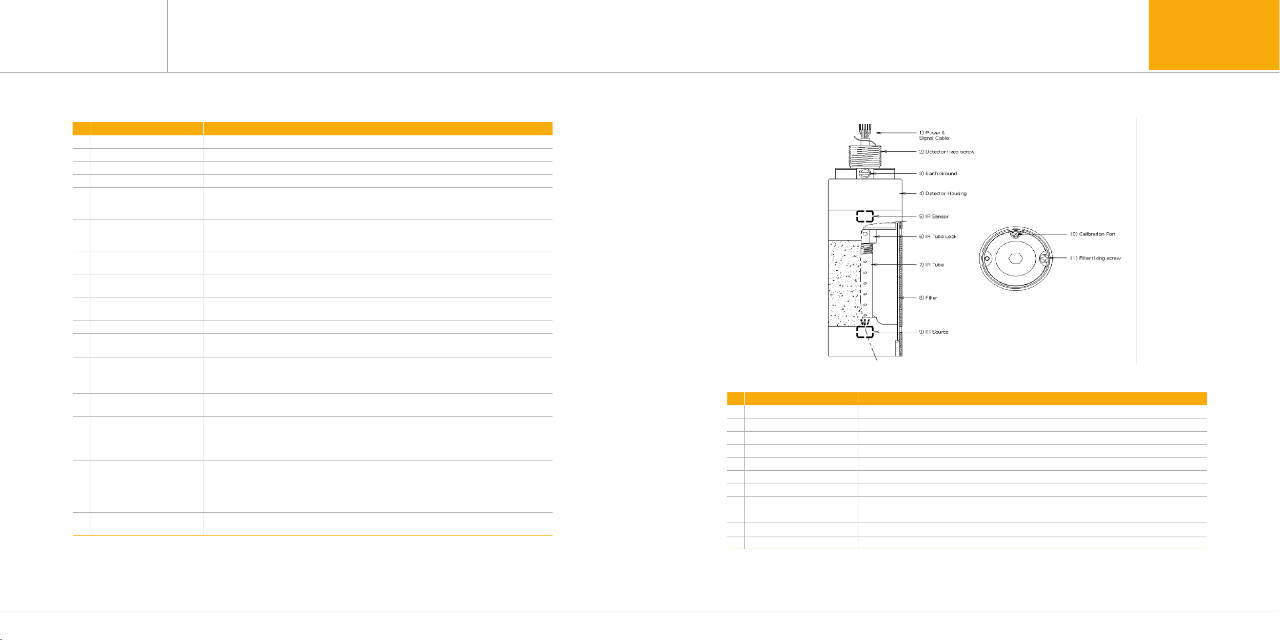
No ITEMS SPECIFICATION
1Power & Signal cable Comprised of power supply input, 4-20mA analog signal, and transmitter communication cable.
2Detector fixed screw Screw processing part for mounting of transmitter
3Earth Ground Outside grounding for protection from outside noise or strong electric field
4Housing Protect PCB Board embedded inside from change in outside environment or impact
5IR Sensor Sensor device for transformation of IR wavelength to electric signals
6IR Tube Lock Screw for fixing of IR tube
7IR Tube Optical path passing infrared wavelength generated in IR lamp
8Filter Filter device for protection of inside optical paths from outside contaminants
9IR Source Lamp for generation of infrared signals
10 Calibration port Inlet for calibration gas upon gas calibration
11 Filter fixing screw Screw for fixing of filter
[Table 1. Components of GIR-3000W]
[Figure 3. Components of GIR-3000W Sensor]
[Table 2 Description on components of GIR-3000W]
GIR-3000W
Instruction Manual
4.2. Components of infrared sensor
4. Name and description of each part4. Name and description of each part

www.gastron.com
12_13
GIR-3000W
Instruction Manual
4.3. Components of GTL-100 4.4. Description on LAMP function
■InthecaseofNormalstate,greenLEDislightedforthewarninglight,andBuzzerdoesnotsound.
■WhensignalsofAlarm-1arereceived,redLEDblinksatanintervalof1second,andBuzzersounds
at an interval of 1 second.
■WhensignalsofAlarm-2arereceived,redLEDislighted,andBuzzersoundscontinuously.
■WhenTroublesignalsarereceived,yellowLEDislighted,andBuzzerdoesnotsound.
[Table 3. Description on main parts of Main PCB]
No NAME DESCRIPTION
1FRONT CASE Explosion-proof CASE made of plastic material, with a transparent window that disperses LED
light to outside.
2CASE RING FRONT CASE that plays the role of cover for prevention of breakaway.
3SEXANGLE BOLT Fastened with headless bolt for prevention of breakaway after assembly of CASE RING
4CASE BODY Body that protects BUZZER and other parts inside.
5BUZZER Generate alarm sound by receiving signals upon occurrence of abnormality.
6FIXED RING Prevent breakaway of sintered filter upon outside impact
7FLAME ARRESTER Shut off inflow of dust, foreign objects, water, GAS, and transmit alarm sound of BUZZER to
outside
8ARREST CAP Protect sintered filter from outside impact
9LED COVER LEDPCBASS'Ycouplingunitcoatedwithmolding.
10 LEDPCBASS'Y Displaystatesbymulti-colorLED's
11 NUT Play the role of fastening to the counterpart assembly item.
12 SHAFT BODY Play the role of fastening to the counterpart assembly item.
13 CABLE WIRE Supply power and transmit DATA.
[Figure 4. Components of GIR-3000W Lamp]
4. Name and description of each part4. Name and description of each part
[Table 4. Description on major parts of Main PCB]
www.gastron.com
14_15
5. Installation5. Installation
GIR-3000W
Instruction Manual
5.2. Configuration of Main PCB
Absolutely no one other the approved users or those of the headquarters in charge of installation and repair should be
allowed to install in the field, open or operate Cover of the installed gas leakage detector. Otherwise serious damages
to life and property may be inflicted. Also, make sure to shut off the power supply and conduct operation after checking
whether explosive GAS remains or flammable substances are present in the surroundings.
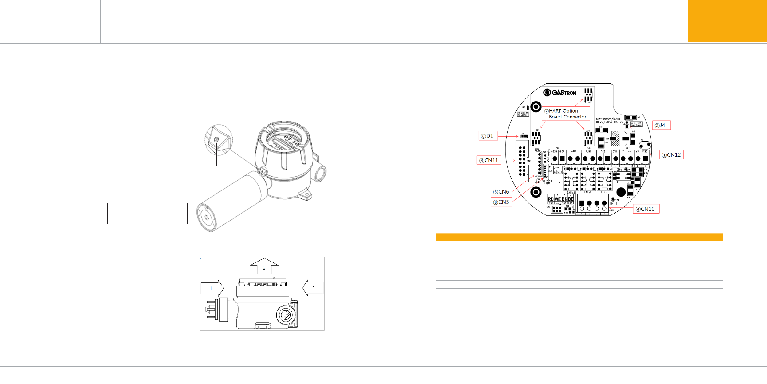
■WhenDisplayPartsareseparated,thelayoutdiagramforMainPCBterminalasfollowscanbeseen.
■ByusingOC1,OC2,OC3oftheabovelayoutdiagram,HARTOptionorRS485MODBUSboardcanbemounted,
and is fixed by using 3 Ø Screw hoe on the to[ left side of Option board.
No NAME DESCRIPTION
1CN12 Power & Output Signal Terminal
2J4 4~20mA Source / Sink selection jumper(ON: Source Type, OFF: Sink Type)
3CN11 Display LCD Connector
4CN10 Sensor Connector
5CN6 Program download Connector
6D1 Status LED (Blinks by the unit of 11 sec in the case of normal operation)
7OC1, OC2, OC3 HART Option Board Connector
8CN5 Warning light (GTL-100) Interface Connector
[Figure 3. Components of GIR-3000W Sensor]
5.1. Separation of Housing Cover
■<Warning-Donotopenduringcurrentsupply.>
■Covercanbeseparatedwhenthecoverforgas
leakage detector is turned counterclockwise after
slotted set
■screwforfixingofbody'scover(M4x1ea)isturned
3~4 turns clockwise by using a hexagonal wrench (M2).
When Cover is separated, LCD unit is displayed.
Slotted set
screw (M4)
Figure when infrared
Sensor(Detector) is mounted
[Figure 3. Slotted set screw]
■WhenCoverisseparated,separateDisplayPartsinthe
following order.
① Simultaneouslypushinwardthefixingchainson
left side and right side on the front face of LCD unit.
② SeparatefromGasdetectorbodybypullingDisplay
Parts forward in the pushed state.
③ MainPCBisinstalledbelowDetectorBodyafter
separation of Display Parts .
[Figure 6.Separation method for Display Part]
5.3. Configuration of power supply and 4-20mA terminal
■<Warning-Conductoperationaftershuttingoffthepowersupplyuponconnectionofpowersupplyterminal.>
■WhenDisplayPartsareseparated,TerminalBlockinMainPCBcanbeseenasshowinthefollowingfigure,
which is separated from Main PCB when held by hand and pulled up.
■Loosenbyturningcounterclockwisetheterminal-fixingscrewsat5placesintheupperpartoftheseparated
TerminalBlockCN12(VISO,+V,mA,-V,ETH)ConnectorbyusingΘdriver,connectDC18-31Vpowersupply
to +, - , and Signal Cable to mA , followed by locking terminal-fixing screws at 5 places clockwise to prevent
terminal from breaking away, and fit it in Main PCB as before separation.
www.gastron.com
16_17
5. Installation5. Installation
GIR-3000W
Instruction Manual
No PCB Silk PIN NAME DESCRIPTION
4~20mA Source Drive (J1 Jumper ON) 4~20mA Sink Drive (J1 Jumper OFF)
1VISO VIS N.C 4~20mA Sink In(+)
2+V ++24V / POWER (+)
3mA mA 4~20mA Source Out 4~20mA Sink Out(-)
4-V -GND / POWER (-)
5ETH ET EARTH
[Table 5. Detailed description on CN8 terminal]
[Figure 8. Configuration of CN11 terminal]
Terminal-fixing Screw
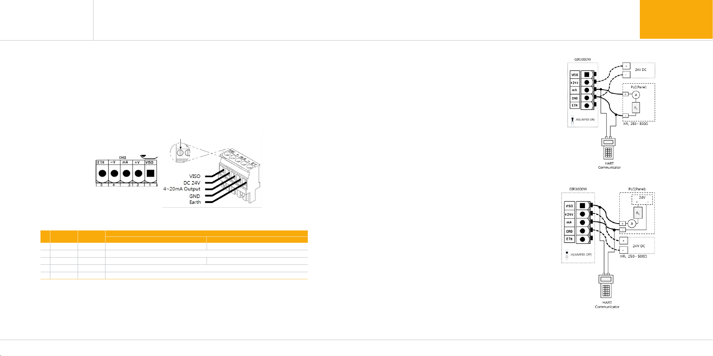
■UponconfiguringtheTerminal,useCVVSorCVVSB2.0sq↑ShieldCable.
■Toconnect4PinTerminaloftheexistingold-styleGIR-3000,fastentheterminalbasedon+24VasNo.2plate.
[Figure 9. Configuration of 4-20mA Source]
[Figure 10. Configuration of 4-20mA Sink]
5.3.2. Wire connection of driving method for
4~20mA Sink
■Connect4-20mASignalterminalonPLCsideto
GIR-3000의'mA',whileGNDterminalisusedin
common with the power supply. And then turn
the J1 Jumper ON.
■HARTCommunicatorcanbeusedonlyinthemodel
using HART Option board
■Connect4-20mASinkoutput(+)terminalonPLC
sidetoVISOterminal,and(-)terminalto'mA'
terminal. And then turn the J1 Jumper OFF.
■HARTCommunicatorcanbeusedonlyinthemodel
using HART Option board.
5.3.1. Wire connection diagram of driving method for
4~20mA Source

5.4.2. Setting for Relay mode
www.gastron.com
18_19
5. Installation5. Installation
GIR-3000W
Instruction Manual
[Figure 11.Configuration of 4-20mA 3Wire Sink]
[Figure 12. Relay and RS485 Terminal]
■FordrivingofRelayofGIR-3000Wproduct,2typesofNormalopenandNormalcloseareoperated.Toallow
settingofMainPCB에Relaydrivingmethod,Jumperisconfiguredwithoperationsettingasfollows.
TER. NO. PIN NO. TERMINAL NAME MODE SETTING
CN8
1TRB OUT J3 A-C connect : A contact ( Normal Open )
J3 B-C connect : B contact ( Normal Close )
2TRB COM
3AL1 OUT J2 A-C connect : A contact ( Normal Open )
J2 B-C connect : B contact ( Normal Close )
4AL1 COM
5AL2 OUT J1 A-C connect : A contact ( Normal Open )
J1 B-C connect : B contact ( Normal Close )
6AL2 COM
[Table 7. Setting for Relay Mode]
5.4.3. Setting for RS485 MODBUS
■MODBUSofGIR-3000WproductisanOptionalitem,andisconnectedtothereceiverunitbythefollowingmethod.
TER. NO. PIN NO. TERMINAL NAME RECEIVER TERMINAL NAME NOTE
CN3 7485A 'TRXD+'or'A'or'P'
8485B 'TRXD-'or'B'or'N'
[Table 8. Description on RS485 terminal]
[Figure 13. Setting for Relay Mode]
■Connect4-20mASinkoutput(+)terminalonPLC
side to VISO terminal, and (-) terminal to (24V DC)
(-)terminal.Connect'mA'terminalofGIR-3000to
'GND'terminal.ThenconnectturntheJ1Jumper
OFF.
5.4.1. Configuration of terminal
5.3.3. Wire connection diagram of driving method for
4~20mA 3Wire Sink
5.4. Configuration of Relay terminal and communication terminal
TER. NO. PIN NO. TERMINAL NAME DESCRIPTION
CN8
1TRB OUT Output mode is determined by TROUBLE RELAY OUTPUT terminal and J3 Jumper setting
2TRB COM TROUBLE RELAY COMMON terminal
3AL1 OUT Output mode is determined by ALARM1 RELAY OUTPUT terminal, J2 Jumper setting.
4AL1 COM ALARM1 RELAY COMMON terminal
5AL2 OUT Output mode is determined by ALARM2 RELAY OUTPUT terminal and J1 Jumper setting.
6AL2 COM ALARM2 RELAY COMMON terminal
CN3 7RS485 A RS485 A terminal
8RS485 B RS485 B terminal
[Table 6.Description on Relay and RS485 terminal]

www.gastron.com
20_21
5. Installation5. Installation
GIR-3000W
Instruction Manual
5.5. Configuration of sensor-connecting terminal
■IRsensormodule(tobereferredtoasGSA920Ahereafter)isconnectedtothetransmitterbyusingCNNo.10terminal ■ ToremotelyconfigureGSA920A,thesensorisinstalledbyusingJunctionBox(GDH-1010)ofthefollowingform,
and connection is made to GIR-3000 transmitter by using component terminal inside Junction Box.
5.6. Configuration of Remote Type connection
TER. NO. PIN NO. TERMINAL NAME 센서케이블 색상 NOTE
CN10
1+SV RED + 24V Sensor Power
2DAT WHITE Transmitter and sensor communication
3-SV BLACK Sensor power GROUND
4ETH BLUE EARTH
[Table 9. Description on sensor-connecting Terminal]
[Figure 15. Configuration of GSA920A connection]
■Configurationofthecablewithwireconnectionto
GSA920A is as follows.
- GSA920A module allows configuration of
extension cable, and is connected by using
CN10 terminal of transmitter.
- GSA920A Option1 is an exclusive output of
4-20mA, while the relevant option is used
upon sole installation of GSA920A
- GSA920A Option2 is an exclusive Zero port,
while the relevant option is used upon sole
installation of GSA920A.
[Figure 14. Sensor-connecting Terminal]
[Figure 16. Configuration of GSA-920A Remote Type]
Wire connection
diagram for Cable terminal
(GSA-920A)
Wire connection
diagram for Cable
terminal
(Receive Unit)
www.gastron.com
22_23
6. Sensor operation Flow
GIR-3000W
Instruction Manual 5. Installation
5.7. Length of installed cable
[Table 10. Installation length for GIR-3000W power supply cable]
PIN NO. mm
2
COPPER RESISTANCE(ohms/m) METERS
12 3.31 0.00521 1439
14 2.08 0.00828 905
16 1.31 0.01318 569
18 0.82 0.02095 357
20 0.518 0.0333 225
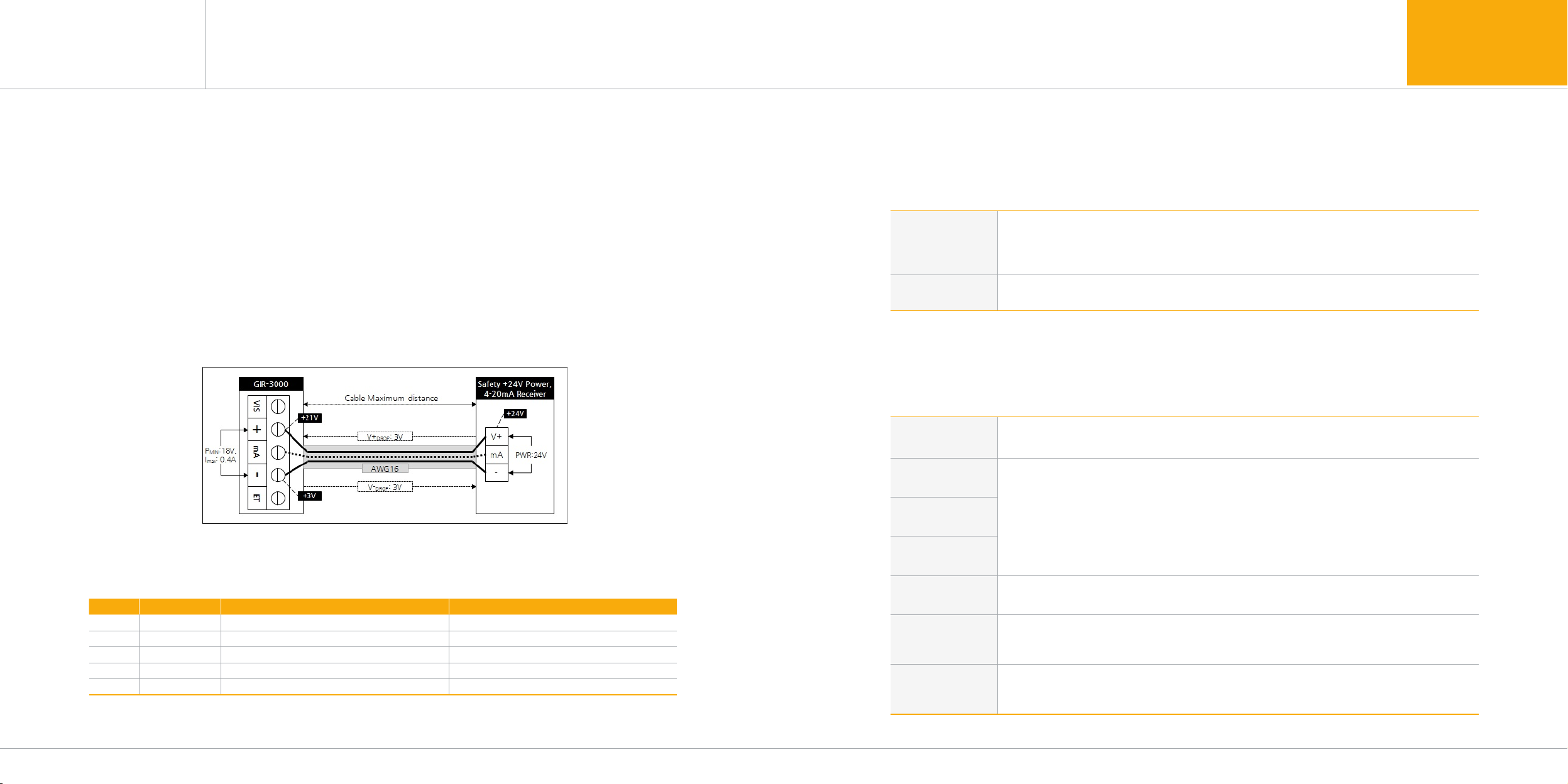
[Figure 17. Calculation of length of installed cable for GIR-3000W]
■ThemaximumlengthbetweenGIR-3000Wandpowersupplyisdeterminedbythewirespecifications.
■Maximuminstallationlength=VMAXDROP÷IMAX÷WIRER/m÷2
■VMAXDROP:MaximumPowerLoopVoltageDrop(=PowerSupplyvoltage-minoperatingvoltage)
■IMAX:MaximumcurrentvalueofGIR-3000W
■WIRER/m:Theresistanceofthewire(ohms/metervalueavailableinwiremanufacturer's
specification data sheet),
■Anexampleforinstallationlengthusing24Vpowersupplyand16AWGisasfollows.
■GIR-3000Wminimumoperatingvoltage=18Vdc
■VMAXDROP=24-18=6V
■IMAX=0.4A(400mA)
■6÷0.4÷0.01318÷2=569.044m≒569m
■Installationlengthofpowersupplycableaccordingtocableclassificationisasshowninthefollowingtable.
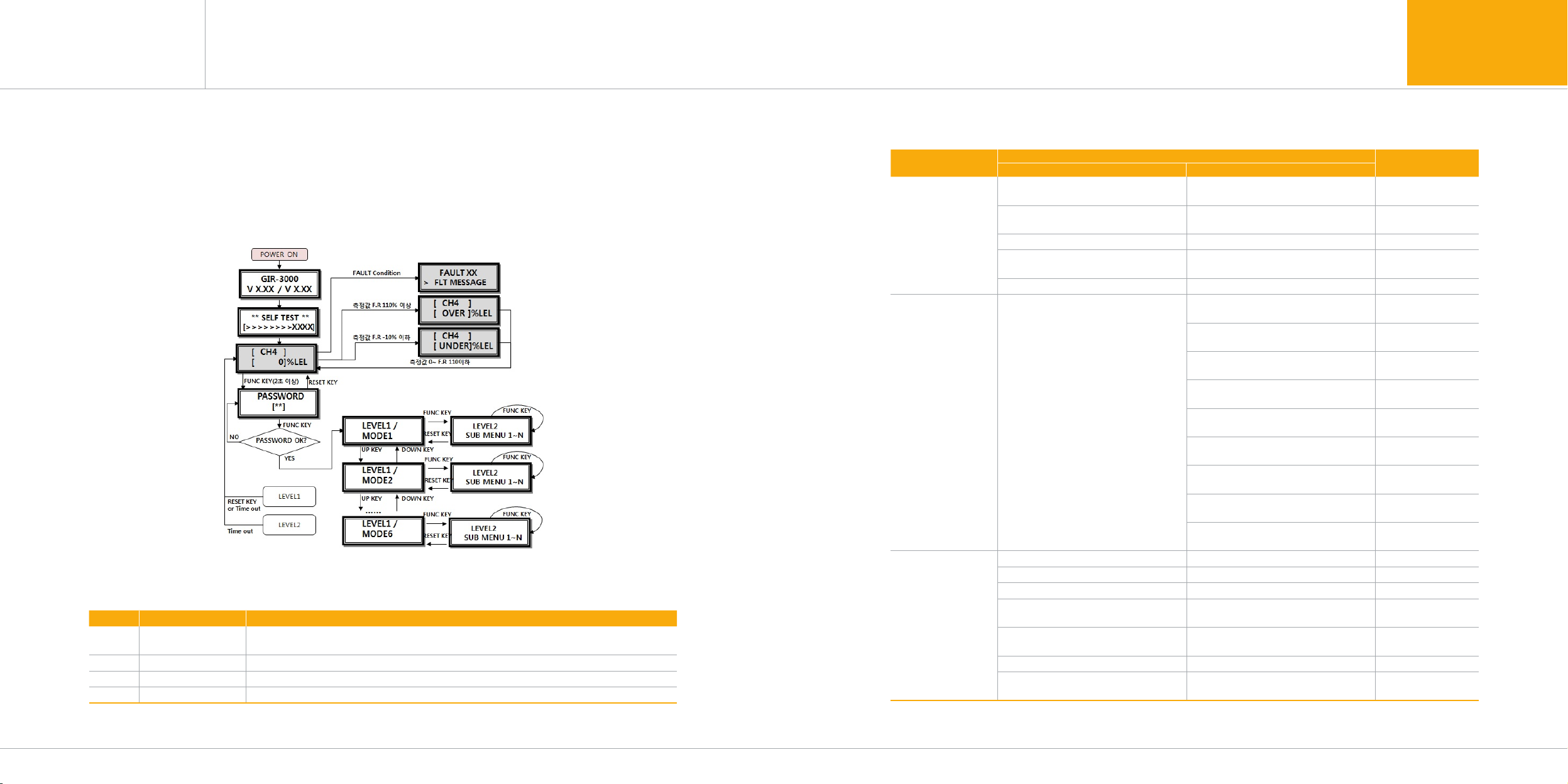
6.1. Initial operation state(Power On)
■WhenpowerissuppliedtothepowersupplyterminalonMAINPCBboardafterwiring,thefollowingcontentscan
be confirmed in the LCD unit, a stabilization time of about 30 minutes is required after initial supply of operation
power, and normal operation occurs from the time of sufficient stabilization.
GIR-3000
V X.XX / V X.XX
- When the power supply is turned ON , model name of LCD(OLED) is displayed in the 1st row, while
- firmware version of the transmitter and firmware version of the sensor unit are displayed in the 2nd row.
-WhenGSA920AfirmwareVersionisbeingRead,"Reading"ismarked,
- WhenReadfails,"Fail"ismarked.
** SELFTEST **
[>>>>>>> 0180]
-SELFTESTisexecutedfor3minutes,while'>'characterinthe2ndrowinformsprogressstatewiththe
- progress count being displayed.
[ CH4 ]
[ WAIT ]%LEL
- When the sensor unit is in waiting state even if progress occurs in a Normal state after SELF TEST,
- measuredGASNAMEisdisplayedinthe1strow,while"WAIT"isdisplayedbytheunitof1secondin
- the 2nd row.
[ CH4 ]
[ 0]%LEL - When it is in gas measurement state while being in Normal state, is operated as follows.
- Measured GAS NAME is displayed in the 1st row, while current measured value and unit are displayed
- in the 2nd row.
- ※Duringcommunicationwiththesensorunit,'#'characterisdisplayedintheleft-sidepartofGASNAME.
- ※DuringHARTcommunicationor485communication,'*'characterisdisplayedintheleft-sidepartof
the 1st row.
- ※WhenENG.ModeisturnedON,thecurrenttemperatureisdisplayedintheleft-sidepartofthe2ndrow.
# [ CH4 ]
[ 0]%LEL
*#[ CH4 ]
[ 0]%LEL
*#[ CH4 ]
[ OVER]%LEL
- When more than 10% the High Scale with setting of gas measurement value is inputted, the text of
- "OVER"isdisplayedbytheunitof1second.Atthistime,4~20mAisoperatedas22mA.
*#[ CH4 ]
[ UNDER]%LEL
-Whenthegasmeasurementvalueisinputtedaslessthan-10%.Thetextof"UNDER"isdisplayedby
- the unit of 1 second, and 4~20mA is operated as 0mA. (2mA upon use of HART)
- The relevant function operates when UNDER function is turned ON.
FAULT 04
> SEN-COMT/O
- When there is abnormality in the device, Fault No. and message are outputted.
- At this time, 4~20mA is operated as 0mA. (2mA upon use of HART)
- The left side is in Fault 4 state occurring when the sensor is not mounted.
6.2. Gas measuring state(Measuring Mode)
■WhenthereisnotabnormalityinSELFTESTafterpoweristurnedONautomaticentryoccursinthefollowingstate
of gas measurement.
www.gastron.com
24_25
6. Sensor operation Flow
GIR-3000W
Instruction Manual
6.4. Menu Configuration Table
LEVEL1 LEVEL2 DEFAULT
NAME PARAMETER
PROGRAMMABLE
MODE
GROUP OF GAS SEL
(GROUP OF GAS SELECT)
HC/PROPANE/CO/CO2/
SO2/VCM/FREON HC
UNIT & TAG SEL.
(UNIT & TAG SELECT) %/%LEL/PPM/PPB %LEL
DECIMAL POINT 0.100/1.00/10.0/100 100
HIGH SCALE ADJ.
(HIGH SCALEADJUST) 1~9999 100
PASSWORD SET 00~99 100
CALIBRATION
MODE
CALIBRATION
[ZERO& SPAN]
ZERO CALIBRATION
[NO, YES] [NO]
ZERO GAS
[0]
ZERO PROCESSING
[SUCCESS / FAIL]
CALIBRATION DATA
[ 0]
SPAN CALIBRATION
[NO, YES] [NO]
SPAN GAS VALUE
[ 0] 50% of Full Scale
[CH4] SPAN GAS
000 [ 0]
SPAN PROCESSING
[SUCCESS / FAIL ]
CALIBRATION DATA
[ 0]
ALARM PROGRAM
MODE
ALARM OPERATING [AUTO/MANUAL] AUTO
ALARM RELAY TYPE DE-ENERGIZED/ENERGIZED DE-ENERGIZED
FAULT RELAY TYPE DE-ENERGIZED/ENERGIZED DE-ENERGIZED
ALARM1 TYPE SEL.
(ALARM1 TYPESELECT) [INCREASE/ DECREASE] INCREASE
ALARM1 LEVEL ADJ
(ALARM1 LEVEL ADJUST) [1~Full Scale] 20
ALARM1 DEAD BAND [0.0~FullScale의10%] 0.0
ALARM1 RELAY CTL
(ALARM RELAY CONTROL) [ON / OFF] ON
6.3. Operation Flow
■AfterPoweristurnedOn,undergotheselfdiagnosisprocessandenterinthemeasuringmode.Atthistime
entering inside system mode is possible through the front face key operation.
■TimeoutbetweenLevel1andLevel2is10seconds,whileitisconfiguredas1hourincalibrationofandTestMode.
■When"RESET"keyistouchedinprogramModescreen,itisreturnedtomeasuringstate,whileitisreturnedtothe
upperstagewhen"RESET"keyistouchedineachprogramsettingscreen.
[Figure 18. Configuration of GIR-3000W mode]
[Table 11.Description on operation key]
ITEM NAME DESCRIPTION
FUNC Function key
Entry function for sensor Mode setting (Input with Magnet-bar for more than 2 seconds in the
measuring mode) . Entry function for the next stage ofLevel2 and saving function for setting values
RESET Reset key Move to the stage before the entered LEVEL
↑Up key Change the setting value Plus for the next stage mode configured in LEVEL1 and Level2
↓Down key Change the setting value Minus for the next stage mode configured in LEVEL1 and Level2
6. Sensor operation Flow
■Operationkeyforcontrolofsensorsystemmodeisdefinedasfollows.

www.gastron.com
26_27
7. System Mode
GIR-3000W
Instruction Manual
[Table 12. Menu Configuration Table]
6.4. Menu Configuration Table
LEVEL1 LEVEL2 DEFAULT
NAME PARAMETER
ALARM PROGRAM
MODE
ALARM1 TIME SET [0~60] SEC 01
ALARM2 TYPE SEL.
(ALARM2 TYPE SELECT) INCREASE/ DECREASE INCREASE
ALARM2 LEVEL ADJ
(ALARM2 LEVEL ADJUST) [1~Full Scale] 40
ALARM2 DEAD BAND [10% of 0.0 ~ Full Scale] 0.0
ALARM2 RELAY CTL
(ALARM RELAY CONTROL) [ON / OFF] ON
ALARM2 TIME SET [0~60] SEC 01
TEST MODE Factory Mode
IR SENSOR DATA
MODE Factory Mode
VERSION
MODE Factory Mode
MAINTENANCE
MODE Factory Mode
485MODBUS
MODE Factory Mode
DEVICE MODE Factory Mode
SYSTEM MODE Factory Mode
7.1. PROGRAM MODE
PROGRMAMMABLE
MODE
- Enter in the Level1 mode after Password checking.
-"SelectPROGRAMMABLEMODEbytouching"↑"keyor"↓"key.
- When Function key is touched at this time, PROGRAMMABLE MODE Level2 sub menu is entered in.
GROUP OF GAS SEL
[ HC ]
-ModeforsettingGasgroupwithGasnamebeingchangedwhenever"↑"keyor"↓"keyistouched.
- (HC/PROPANE/CO/CO2/SO2/VCM/FREON)
TYPE OF HC
[ CH4 ] -ModeforsettingGasnamewithGasnamebeingchangedwhenever"↑"keyor"↓"keyistouched.
TYPE OF HC
[ CH4 ]
- Mode for setting Gas measurement unit with the Gas measurement unit being changed whenever
- "↑"keyor"↓"keyistouched.(%/%LEL/PPM/PPB).
DECIMAL POINT
[ 100 ]%LEL
- Mode for setting position of decimal point with the position of decimal point being changed whenever
- "↑"keyor"↓"keyistouched.(0.100/1.00/10.0/100)
HIGH SCALE ADJ.
[ 100 ]%LEL
- Mode for setting High scale value to be displayed at the time of Full Range with the scale value being
- increasedordecreasedwhenever"↑"keyor"↓"keyistouched.(1~9999)
PASSWORD SET
[00] - Mode for setting Password , which is checked upon entering in the Program Mode. ( 0~99 )
6. Sensor operation Flow

www.gastron.com
28_29
GIR-3000W
Instruction Manual 7. System Mode7. System Mode
7.2. CALIBRATION MODE 7.2.2. Span Calibration
7.2.1. Zero Calibration
CALIBRATION
MODE
- Enter in Level1 mode after Password checking.
-SelectCALIBRATIONMODEbytouching-"↑"keyor"↓"key.
- Calibration Mode Level2 sub menu is entered in when Function key is touched at this time.
CALIBRATION
[ZERO]
- Calibration mode is entered in if FUC key is touched when it is [ZERO].
-ZEROandSPANcanbeselectedbytouching"↑"keyor"↓"key.
ZERO CALIBRATION
[YES] -ZeroCalibrationisexecutedifFUNCkeyistouchedwhenitis[TES]bytouching"↑"keyor"↓"key.
ZERO GAS
[ 0]%LEL
- Zero calibration is automatically executed if FUNC key is touched when the measured value is
- stabilized after clean air or 100% nitrogen as the gas is injected in the sensor unit at the flow rate of
- 1000mL/min for about 1 minute by using a calibration apparatus.
ZERO PROCESSING
>>>> - Processing state of Zero calibration is displayed.
ZERO PROCESSING
SUCCESS -WhenZerocalibrationissuccessful,"ZEROCALIBRATIONSUCCESSisdisplayedinLCDDisplayfor
- 2 seconds , and then converted to CALIBRATION DATA Mode.
-WhenZeroCalibrationisnotsuccessful,"ZEROCALIBRATIONFAIL"isdisplayedfor2seconds,
- and then converted to CALIBRATION DATA Mode.
ZERO PROCESSING
FAIL
CALIBRATION DATA
[WAIT ]%LEL
- Mode for displaying measured values after calibration, as a function for checking whether calibration
- was normal after execution of calibration.
-"WAIT"isdisplayedfor2secondsafterenteringinSubmenu,displayingthecurrentmeasurementstate.
-WhenRESETkeyistouched,itisreturnedto"CALIBRATIONMODE"
- When FUNC key is touched, Span Calibration menu is entered in.
CALIBRATION DATA
[ 0]%LEL
SPAN CALIBRATION
[YES] -SpanCalibrationModeisenteredinifFUNCkeyistouchedwhenitis[YES]bytouching"↑"keyor"↓"key.
[CH4] SPAN GAS
090 [ 50]%LEL
- Span calibration is automatically executed if FUNC key is touched when the measured value is
- stabilized after the standard gas is injected in the sensor unit at the flow rate of 1000mL/min for about
- 90 seconds by using a calibration apparatus.
SPAN GAS VALUE
[ 50]
- Mode for setting standard gas value where FUNC key is touched after the value is set by touching
- "↑"keyor"↓"key.(1~FullScale)
SPAN PROCESSING
>>>> - Processing state of Span calibration is displayed.
SPAN PROCESSING
SUCESS -WhenSpancalibrationissuccessful,"SPANPROCESSINGSUCCESS"isdisplayedinLCDDisplayfor
- 2 seconds, and then converted to CALIBRATION DATA Mode.
-WhenSpanCalibrationisnotsuccessful,"SPANPROCESSINGFAIL"isdisplayedinLCDDisplayfor
- 2 seconds, and then converted to CALIBRATION DATA Mode.
SPAN PROCESSING
FAIL
CALIBRATION DATA
[WAIT ]%LEL - Mode for displaying measured values after calibration, as a function for checking whether calibration
- was normal after execution of calibration.
-"WAIT"isdisplayedfor2secondsafterenteringinSubmenu,displayingthecurrentmeasurementstate.
-When"RESET"keyor"FUNC"keyistouched.itisreturnedto"CALIBRATIONMODE".
CALIBRATION DATA
[50]%LEL
■DuetothecharacteristicsofGasdetector,astabilizationtimeofatleastabout30minutesisrequiredaftersupplyof
power, and the management criteria may be varied with field conditions..

www.gastron.com
30_31
GIR-3000W
Instruction Manual 7. System Mode7. System Mode
7.3. ALARM MODE 7.3. ALARM MODE
ALARM PROGRAM
MODE
- Enter in Level1 mode after password checking.
-SelectALARMMODEbytouching"↑"keyor"↓"key.
- ALARM MODE Level2 is entered in when Function key is touched at this time.
ALARM OPERATING
[ AUTO ] -ModeforsettingResettingmethodafterAlarmoperationwithchangeto"AUTO"and"MANUAL"
- whenever"↑"keyor"↓"keyistouched.
-"AUTO"ModeisthefunctionforautomaticresettingofAlarm,while"MANUAL"Modeisthefunctionfor
- resetting of Alarm by pushing the Reset key.
ALARM OPERATING
[ MANUAL]
ALARM RELAY TYPE
DE-ENERGIZED
-ModeforsettingRelaydrivingmethodafterAlarmoperationwithchangeto"DE-ENERGIZED"and
- "ENERGIZED"whenever"↑"keyor"↓"keyistouched.
-"DE-ENERGIZED"isthefunctionfordeactivationofenergizermode,while"ENERGIZED"activatesthe
- energizer mode.
FAULT RELAY TYPE
DE-ENERGIZED
-ModeforsettingRelaydrivingmethodafterFAULToperationwithchange"DE-ENERGIZED"and
- "ENERGIZED"whenever"↑"keyor"↓"keyistouched.
-"DE-ENERGIZED"isthefunctionfordeactivationofenergizermode,while"ENERGIZED"activatesthe
- energizer mode.
ALARM1 TYPE SEL.
[INCREASE ]
-ModeforsettingoperationdirectionforAlarm1with"INCREASE"or"DECREASE"displayedwhenever
- "↑"keyor"↓"keyistouched.
-"INCREASE"ModeisthemodeoperatingwhenitislargerthanorsameasthesettingvalueforAlarm1
- while"DECREASE"Modeisthemodeoperatingwhenitissmallerthanorthesameasthesettingvalue
- for Alarm1.
ALARM1 TYPE SEL.
[DECREASE ]
ALARM1 LEVEL ADJ
[ 20]
- Mode for setting the Alarm1 level value with the Alarm 1 value increased or decreased whenever
- "↑"keyor"↓"keyistouched.
-If"FUNC"keyistouchedwhenthedesiredAlarm1valueisdisplayed,andthenextAlarmProgramitem
- is entered in.
ALARM1 DEAD BAND
-ModeforsettingtherangeforoperationofAlarm1withincreaseordecreasewhenever"↑"keyor
- "↓"keyistouched.
- Function where Alarm1 operates at the Alarm1 value plus Deadband value when Alarm1 is in
- "INCREASE"ModeandAlarm1isclearedattheAlarm1valueminusDeadbandvalue.
-If"FUNC"keyistouchedwhenthedesiredvalueisdisplayed,Deadbandvalueissetandthenext
- Alarm Program item is entered in.
ALARM 1RELAY CTL
[ ON]
-ModeforsettingwhethertocontrolRelaycontactwhenAlarm1operateswith"ON"or"OFF"displayed
- whenever"↑"keyor"↓"keyistouched.
- If it is turned ON, Relay operates upon operation of Alarm 1. When it is turned OFF, Relay does not
- operate when Alarm 1 operates.
ALARM1 TIME SET
[ 01]
-ModeforsettingdelaytimeforAlarm1withthevalueincreasedordecreasedwhenever"↑"keyor
- "↓"keyistouched.
-Displayedfigureshowsseconds,beingdisplayedfrom0to60.If"FUNC"keyistouchedwhenthe
- desired value is displayed, alarm delay time is set and then the next Alarm Program item is entered in,
ALARM2 TYPE SEL.
[INCREASE ]
-ModeforsettingthedirectionforoperationofAlarm2with"INCREASE"or"DECREASE"displayed
- whenever"↑"keyor"↓"keyistouched.
-"INCREASE"Modeisthemodeoperatingwhenitislargerthanorthesameasthesettingvaluefor
- Alarm2,while"DECREASE"Modeisthemodeoperatingwhenitissmallerthanorthesameasthe
- setting value for Alarm2.
ALARM2 TYPE SEL.
[DECREASE ]
ALARM2 LEVEL ADJ
[ 40]
-ModeforsettingthevalueofAlarm2levelwithAlarm2valueincreasedordecreasedwhenever"↑"key
- or"↓"keyistouched.
-If"FUNC"keyistouchedwhenthedesiredAlarm2valueisdisplayed,Alarm2valueisset,andthen
- Alarm Program item is entered in.
ALARM2 DEAD BAND
- Mode for setting of operation range for Alarm2, with the value increased or decreased whenever
- "↑"keyor"↓"keyistouched.
- Function where Alarm2 operates at the Alarm1 value plus Deadband value when Alarm2 is in
- "INCREASE"ModeandAlarm2isclearedattheAlarm1valueminusDeadbandvalue.
-If"FUNC"keyistouchedwhenthedesiredvalueisdisplayed,Deadbandvalueissetandthenext
- Alarm Program item is entered in.
ALARM2 RELAY CTL
[ ON]
-ModeforsettingwhethertocontrolRelaycontactwhenAlarm2operateswith"ON"or"OFF"displayed
- whenever"↑"keyor"↓"keyistouched.
- If it is turned ON, Relay operates upon operation of Alarm 2. When it is turned OFF, Relay does not
- operate when Alarm 2 operates.
ALARM2 TIME SET
[ 01]
-ModeforsettingdelaytimeforAlarm2withthevalueincreasedordecreasedwhenever"↑"keyor
- "↓"keyistouched.
-Displayedfigureshowsseconds,beingdisplayedfrom0to60.If"FUNC"keyistouchedwhenthe
- desired value is displayed, alarm delay time is set and then it returns to ALARM PROGRAM MODE.

www.gastron.com
32_33
GIR-3000W
Instruction Manual 8.Troubleshooting8.Troubleshooting
8.1. Fault List 8.2. Recovery List
[Table 13. Fault List]
FAULT MESSAGE DESCRIPTION & CONDITION CAUSE FOR OCCURRENCE
FAULT0
">TSM-MEMC/S"
When Memory(FLASH, RAM) Check Sum error occurs
inside the transmitter Transmitter inside MPU defective
FAULT1
">TSM-EEPROM"
When EEPROM Check Sum error or EEPROM operation
error occurs inside the transmitter Transmitter inside EPROM defective
FAULT2
">SEN-MEMC/S"
When Memory(FLASH, RAM) Check Sum error occurs
inside the sensor unit Sensor Unit inside MPU defective
FAULT3
">SEN-EEPROM" When operation error occurs inside the sensor unit Sensor Unit inside EEPROM defective
FAULT4
">SEN-COMT/O"
When communication between Transmitter and
Sensor Unit fails
Communication between Transmitter and
Sensor Unit defective
FAULT5
">SEN-CHANGE(DET)"
When IR Detector Channel inside the sensor unit lies
below the effective voltage range (0.1V)
1) Waveguide inside sensor Unit contaminated
2) IR sensor inside sensor unit broken down
FAULT6
">SEN-CHANGE(REF)"
When IR Reference Channel inside the sensor unit lies
below the effective voltage range (0.1V)
1) Waveguide inside sensor Unit contaminated
2) IR sensor inside sensor unit broken dow
FAULT7
">SEN-CHANGE(OPT)"
When IR Detector Channel and Reference Channel
inside the sensor unit lie simultaneously below the
effective voltage range (0.1V)
1) Waveguide inside sensor Unit contaminated
2) IR sensor inside sensor unit broken down
3) IR lamp inside sensor unit broken down
FAULT8
">CLIBRATIONERR" Calibration Error Erroneous Calibration Parameter
FAULT9
">SEN-D,RCHLOW"
When IR Detector Channel and Reference Channel
inside the sensor unit lie simultaneously below the
effective voltage range (0.1V)
1) Waveguide inside sensor Unit contaminated
2) IR sensor inside sensor unit broken down
3) IR lamp broken down
FAULT10
">SEN-TEMPERATURE"
When IR inside temperature sensor deviates from the
effectivemeasurementrange(+80~-40℃)
Surrounding temperature inspection,
temperature sensor inside sensor unit defective
FAULT11
">SEN-VERSION"
When Version of the sensor unit sensor received from
transmitter is not an effective value (0~99) Sensor Unit program error
FAULT12
">VINLOWVOLTAGE"
When the input voltage value is less than the minimum
value (17V) Inspection of input power supply for transmitter
FAULT13
">HWVERSIONERR" HW VERSION ERROR Transmitter inside MPU defective
FAULT14
">SENSORHUNTING" When the gas measurement value is repeatedly hunting Sensor output state defective or checking for
input power supply noise
[Table 14. Recovery List]
No CAUSE FOR OCCURRENCE COPING MEASURE
1MPU inside transmitter defective Replace Transmitter Main Board
2EPROM inside transmitter defective 1) Revise and recalibrate Parameter after execution of plant initialization
2) Replace Main Board when the same phenomenon occurs
3MPU inside sensor unit defective Replace Sensor Unit
4EEPROM inside sensor unit defective 1) Revise and recalibrate Parameter after execution of plant initialization
2) Replace Sensor Unit when the same phenomenon occurs
5Communication between Transmitter and
Sensor Unit defective
1) Check wire connection between Transmitter and Sensor Unit
2) Check supplied voltage for Sensor Unit when there is no abnormality in wire
connection
3) Replace Sensor Unit when there is no abnormality in supplied voltage
4) Replace Transmitter Main Board when the same error occurs
6Waveguide for sensor Unit contaminated
1) Conduct cleaning operation or replacement of waveguide or optical window
after removing the sensor filter
2) Execute recalibration after waveguide action
7IR sensor broken down Replace sensor Unit
8Erroneous Calibration Parameter 1) Execute recalibration
2) Replace sensor Unit when the same symptom is discovered after recalibration
9IR lamp broken down Execute recalibration after replacement of IR lamp
10 Temperature sensor inside sensor unit
defective Replace sensor Unit
11 Sensor Unit program error Replace sensor Unit
12 Inspection of input power supply for
transmitter Inspect the range of input power supply for transmitter

www.gastron.com
34_35
GIR-3000W
Instruction Manual 10. Outline drawing and Dimensions9. Interface conguration
9.1. MODBUS RS485 10.1. Standard Type
[Figure 19. Outline drawing for GIR-3000W Standard Type]
CLASSIFICATION ADDRESS BITS DESCRIPTION
Measured gas
concentration 30001 BIT15~0 Gas measurement value (Integer type / Decimal Point not considered)
Setting value for
High Scale 30002 BIT15~0 Setting value for High Scale (Integer type / Decimal Point not considered)
1st Alarm setting value 30003 BIT15~0 1st Alarm setting value (Integer type / Decimal Point not considered)
2nd Alarm setting value 30004 BIT15~0 2nd Alarm setting value (Integer type / Decimal Point not considered)
Gas detector
state value 10000
BIT0 Alarm 1 Active state
BIT1 Alarm 2 Active state
BIT2 Fault Active state
BIT3 Maintenance Mode state
BIT4 Test Mode state
BIT5 Calibration Mode state
BIT6 Reserved
BIT7 Toggle Bit(Bit inversion at an interval of 2 Sec)
Outside Test 3BIT0~7 Setting for Gas detector Test Mode
Outside Reset 2BIT0~7 Setting for Gas detector Test Mode
9.1.1. Interface setting
9.1.2. MODBUS RS485 Register map
■DataFormat:RTU
■Baudrate:9600bps
■Databits:8bits
■Stopbit:1bits
■Parity:Even
■Seewww.modbus.orgforotherdetails
[Table 15.Configuration of RS485 MODBUS Address]

www.gastron.com
36_37
GIR-3000W
Instruction Manual 10. Outline drawing and Dimensions
10.3. Upon coupling of warning light
[Figure 20. Outline drawing for GTL-100] [Figure 21. Outline drawing for coupling of GIR-3000W warning light]
10. Outline drawing and Dimensions
10.2. Warning light GTL-100
www.gastron.com
38_39
11. Notes before installation
GIR-3000W
Instruction Manual
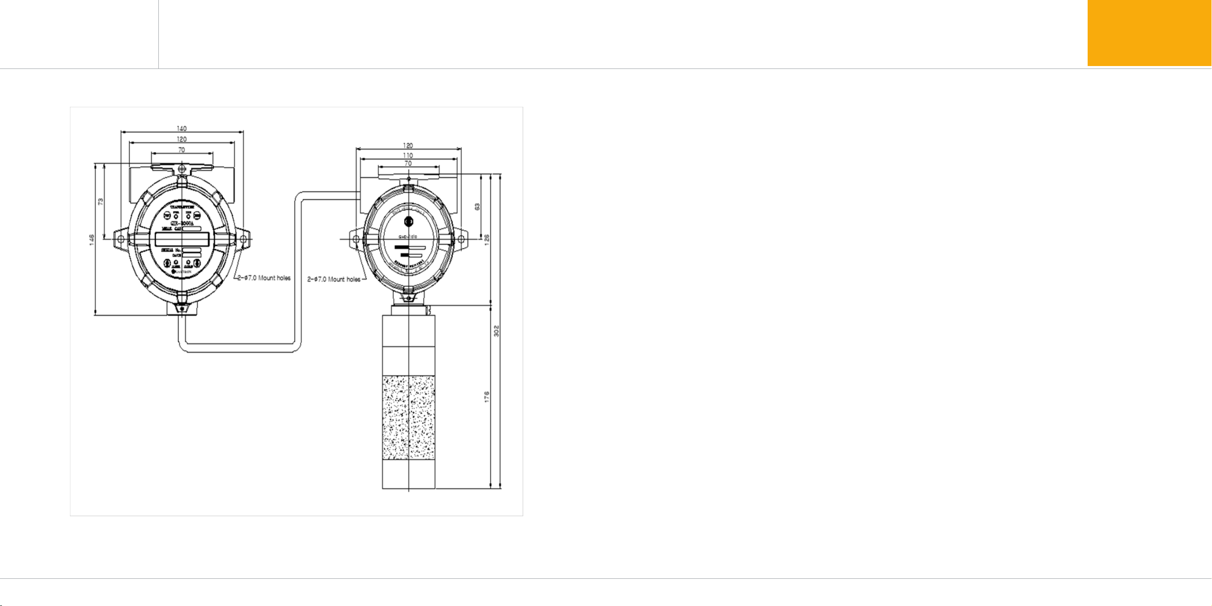
10.4. GIR-3000W Remote Type
[Figure 22. GIR-3000W remote Type]
10. Outline drawing and Dimensions
11.1. Selection of installation place (Data from occupational safety and health regulations)
11.2. Selection of installation place(Data from safety management regulations for high-pressure gas)
The place to install the gas leakage detection alarm is as follows.
■Surroundingsofchemicalequipmentoraccessoryequipmentwithariskofgasleakagesuchascompressor,
valve, reactor, piping connection part, etc. dealing with combustible and toxic substances that are installed inside and
outside buildings
■Placesforeasydwellingofgasaroundmanufacturingequipmentwithignitionsourcessuchasheatingfurnace,etc.
■Surroundingsofconnectionpartofchargingequipmentforcombustibleandtoxicsubstances
■Substation,powerdistributionpanelroom,controlroom,etc.positionedwithinexplosion-proofarea
■Otherplacesforespeciallyeasydwellingofgas
Gas detector for gas leakage detection alarm should be installed close to the leakage parts with a risk of gas leakage.
However, for the places with easy dwelling of leaked gas although direct gas leakage is not expected, it should be
installed at a spot such as No. 1 of the following places.
■Gasleakagedetectionalarminstalledoutsideabuildingshallbeinstalledataspotforeasydwellingofgasby
considering wind direction, wind velocity, specific gravity of gas, etc.
■Whenthespecificgravityofthedetectiontargetgasislargerthanthatofair,thegasleakagedetectionalarm
installed inside a building should be installed at a lower part in the building, while it should be installed near
ventilation hole of the building or at an upper in the relevant building when the gas is lighter than air.
■AlarmofthegasleakagedetectionalarmshouldbeinstalledataplacewiththeGasdetectorinstalledandplaces
for permanent residence of workers.
Table of contents
Other GASTRON Measuring Instrument manuals


