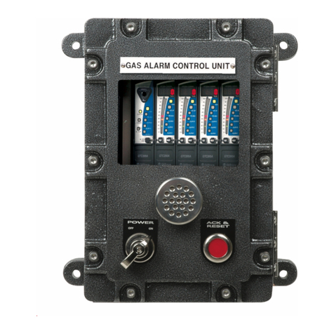
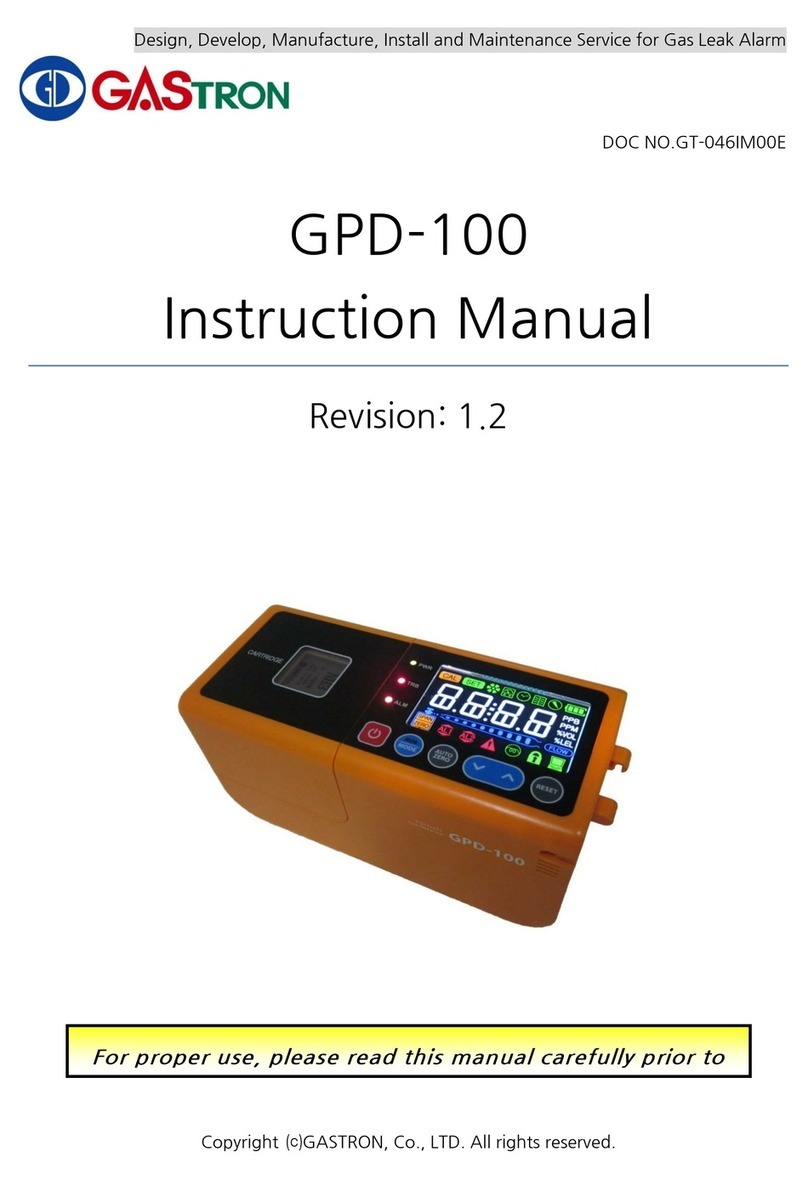
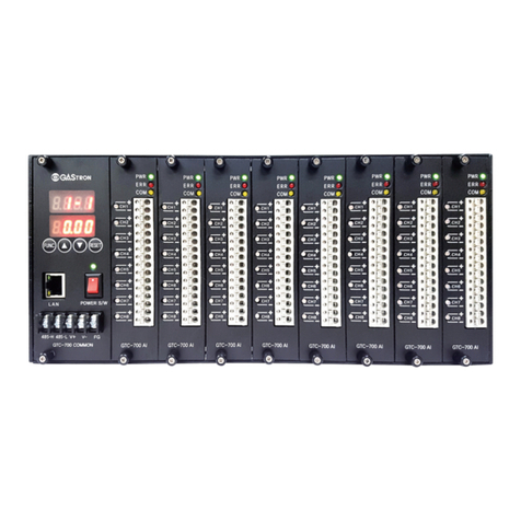
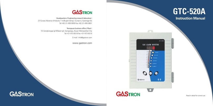
GASTRON GTD-5000 User manual

GTD-5000
Instruction Manual
Read in detail for correct use.
Headquarters / Engineering research laboratory :
23 Gunpo Advance d Industry 1-ro(Bugok-dong), Gunpo-si, Gyeonggi-do
Tel +82-31-490-0800 Fax +82-31-490-0801
Yeongnam business office / Plant :
55 Gonghangap-gil 85beon-gil, Gangseogu, Busan Metropolitan City
Tel +51-973-8518 Fax +51-973-8519
E-mail : [email protected]
www.gastron.com

Gas & Flame
Detection System
GTD-5000
Instruction Manual
www.gastron.com
02_03
Greetings
When abnormalities occur after purchasing the product,
please contact the following address.
·Address : 23 Gunpo Advanced Industry 1-ro,
Gunpo-si, Gyeonggi-do
·Tel : 031-490-0800
·Fax : 031-490-0801
·URL : www.gastron.com
·e-mail : [email protected]
We sincerely thank you for purchasing the product of Gastron Co. Ltd.
Our Gastron Co.Ltd. is a company specialized in Gas detector and Gas Monitoring System, being
recognized by many consumers due to the best quality and use convenience. We always enable you
consumers to find desired products nearby and are ceaselessly studying and striving for development
of Gas detectors satisfying customers. From now on, solve all anguishes concerning Gas detector with
the products of Gastron Co. Ltd, We Gastron Co. will take a responsibility and give you satisfaction.
In the present instruction manual, operation method for Gas detector as well as simple methods for
maintenance and repair, etc. are recorded If you read it in detail and keep it well, for reference when
you have questions, then it will give you much help.
The present product and the product manual can be changed without advance notice for performance improvement and
use convenience of the product.
■ For accurate operation of Gas detector, check up and calibrate for more than once in every 6 months.
( * See No. 13 of KOSHA GUIDE : P-135-2013 / 8.3 paragraph on qualification and calibration)
■ For accurate operation of Gas detector, checkup and calibration with calibration gas before measurement
is recommended.
■
When not calibrated, it may cause malfunction of the equipment due to problems resulting from Sensor aging.
■ When the present instrument should be dismantled, those with professional skills for Gas detector should
conduct the operation.
■ For power supply cable, wire specifications should be determined by referring to the item of "Length of
installed cable".
■ For the contents on checkup and calibration of Gas detector, please use our company's engineering
department , e-mail, or web site.
* KOSHA GUIDE : P-135/6-2018
Calibration should be executed at the periods required by the manufacturer, and should be executed
every quarter unless there are separate calibration periods.

www.gastron.com
04_05
ContentsContents
GTD-5000
Instruction Manual
7. System Mode ······················································································ 22
7.1. Mode Configuration ··········································································· 22
7.2. Detailed Menu Configuration ··································································· 22
7.3. Configuration Mode ··········································································· 24
7.4. Program setting··············································································· 26
7.5. Zero Calibration ·············································································· 27
7.6. Span Calibration ·············································································· 28
7.7. Alarm mode ·················································································· 29
8. Troubleshooting ··················································································· 33
8.1. Fault List ····················································································· 33
8.2. Warning List ·················································································· 33
8.3. Recovery List ················································································ 34
9. Interface Configuration ············································································ 35
9.1. MODBUS RS485 ·············································································· 35
9.1.1. Interface setting ········································································ 35
9.1.2. MODBUS RS485 Register map ·························································· 35
9.2. MODBUS/TCP Interface ······································································· 36
9.2.1. Interface setting ········································································ 36
9.2.2. MODBUS TCP/IP Register map ·························································· 36
10. Drawings and Dimensions ········································································· 39
10.1. GTD-5000 Standard Type ····································································· 39
10.1. GTD-5000 & PY-1000 ········································································ 40
10.2. GTD-5000 & PY-2000 ········································································ 41
11. Precautions before Installation ····································································· 42
11.1. Selecting a Place for Installation (Occupation Safety and Health Act Data) ·························· 42
11.2. Selecting a Site for Installation (High-Pressure Gas Safety Control Act Data) ························ 42
11.3. Precautions during Installation ································································· 42
11.4. Cable Wiring Work ············································································ 43
12. Revision History ··················································································· 44
1. Overview ··························································································· 6
2. Configuration ························································································ 6
3. Specification ······················································································· 7
3.1. Basic Specifications ··········································································· 7
3.2. Mechanical Specifications ····································································· 7
3.3. Electrical Specifications (Standard Type) ························································ 8
3.4. Environmental Specifications ··································································· 9
4. Name and Description of Each Part ································································ 10
4.1. Components ················································································· 10
4.2. Front Display Configuration ···································································· 12
5. Installation ························································································· 13
5.1. Detachment of Housing Cover ································································· 13
5.2. Terminal PCB Configuration ···································································· 14
5.3. Power and 4-20mA Signal Configuration························································ 14
5.3.1. Power and Signal Terminal Configuration ················································· 14
5.3.2. Power and 4~ 20mA Source Configuration ··············································· 15
5.3.3. Power and 4~ 20mA Sink Configuration ·················································· 15
5.3.4. Power and 4~20mA 3Wire Sink Configuration ············································ 15
5.4. Alarm and RS485 Signal Configuration ·························································· 16
5.4.1. RS485& Relay Terminal Configuration ···················································· 16
5.4.2. Trouble Relay Output Configuration ······················································ 16
5.4.3. Alarm1 Relay Output Configuration ······················································· 16
5.4.4. Alarm2 Relay Output Configuration ······················································· 16
5.4.5. RS-485 Terminal Configuration ························································· 17
5.5. Ethernet Signal Configuration ·································································· 17
5.6. Pyrolyzer Configuration ········································································ 18
5.7. Installation Cable Length ······································································· 19
6. Operation ·························································································· 20
6.1. Power On ···················································································· 20
6.2. Measuring Mode ·············································································· 21
6.3. Internal Mode Configuration ···································································· 21

www.gastron.com
06_07
3. Specication
GTD-5000 gas detector has been developed to detect gas leaked from industrial sites and various gases generated from
factories, gas storages, and manufacturing processes that produce or use flammable gases and to prevent accidents in
advance. GTD-5000 gas detector is a sampling type that is installed in areas with gas leak hazards. It continuously monitors
gas leak at all time, displays measurements on LCD built in the gas detector, and provides, DC 4-20 mA standard output, RS-
485 network signal, PoE (Power over Ethernet) network signal, and relay contact signal in an event of gas leak alarm. Also,
DC 4-20 mA standard output is possible for connection up to max. 2,500 m of output signal transmission distance between the
gas detector and receiver (When CVVS or CVVSB 1.5s sq↑ shield cable is used). RS-485 network signal can be transmitted
up to 1,000 m (When a cable designated for RS-485 is used) and PoE (Power over Ethernet can be transmitted up to 100 m.
3.1. Basic Specifications
ITEMS SPECIFICATION
Measuring Type Auto Sampling type
Measuring Type Flexible Numeric Display LED
Measuring Method
- Electrochemical / Cartridge
- Catalytic / Cartridge
- Semiconductor / Cartridge
- Photoionization detector(PID) / Cartridge
Detectible Gas Flammable gas, Toxic gas, Oxygen (Note1)
Measuring Range Capable to display 000.0 ~ 9999 (Note 1)
Accuracy ≤ ±3% / Full Range
Zero Drift ≤ 2% / Full Range
Response Time
Differ by sensor module. Refer to sensor specification or contact us for
special gas.
Pump Type
Diaphragm Pump
Flow Rate
100 ~ 1,000 ml (Normal 300~500ml / min)
Gas Sample Line
Within 30 m ( 1/4" Tube )
Approvals Classification CE ( EN50270:1999 )
Basic Interface Analog 4-20mA current interface
Cartridge Type Option RS485, PoE Interface, Pyrolyzer option
Warranty Transmitter 2Year
Sensor 1Year
3.2. Mechanical Specifications
ITEMS SPECIFICATION
Dimension / mm
Standard Type 70(W) × 144(H) × 160(D)
PY-1000 M Connecting Model 70(W) × 242.5(H) × 160(D)
PY-2000 M Connecting Model 70(W) × 267.5(H) × 200(D)
Weight including Sensor
Standard Type App. 1.75kg
PY-1000 M Connecting Model App. 4kg
PY-2000 M Connecting Model App. 4.75kg
Mounting type Wall mount
Vacuum Tube (Sample gas vent/inlet) 1/4" Teflon Tube
Body material Aluminum alloy
GTD-5000 case is made of steel. This product can be installed in areas with leak hazards of all toxic and flammable gases.
4-Digit LCD built in the gas detector displays gas leak status at installed site. Internal configuration consists of display part
that shows measurements, main control part that measures and controls gas concentration and flow rate, and terminal part
that output current output (DC 4-20 mA), RS-485 network signal, PoE (Power over Ethernet) network signal, or Alarm signal.
Sensor is a cartridge type that can be detached and it is designed to be easily exchanged by the user.
2. Conguration
1. Overview
GTD-5000
Instruction Manual
[Figure 1. GTD-5000 Overview]
Diaphragm Pump &
Flow Sensor
Sensor Cartridge
Terminal Unit
Main Unit
Display Unit
Safety Power Supply Unit
(24VDC)
Safety Controller
(PLC or DCS)
GTD-5000 Gas Detector
Hazardous Area (Filed) Safe Area
Legend
Control Signal
External Interface
Power Line
Gas
Measurement
Gas
Sampling & Sensor Unit
※ Note1. Refer to the measured gas list for measured gases and their ranges. Contact us for special gas.
Vacuum
Exhaust

www.gastron.com
08_09
3. Specication
3.3. Electrical Specifications (Standard Type)
ITEMS SPECIFICATION
Input Voltage(Standard)
※ Customer supplied PSU must meet
requirements IEC1010-1 and CE
Marking requirements.
Absolute min:
Nominal:
Absolute max:
Ripple maximum allowed:
18V
24V
31V
1V pk-pk
Input Voltage(PoE option) 48 VDC Power-over-Ethernet (IEEE 802.3af compliant)
Wattage(Cartridge Type) Max. wattage:
Max. current:
6.7W @+24 VDC
280mA @+24 VDC
Wattage(Cartridge and Pyrolyzer) Max. wattage:
Max. current:
12.5W @+24 VDC
520mA @+24 VDC
Analog output Current
0-20mA(500 ohms max load)
All readings ± 0.2mA
Measured-value signal:
4mA(Zero) to 20mA(Full Scale)
Fault:
0-100% LEL:
100-109%LEL:
Over 110% LEL:
Maintenance:
0mA
4mA - 20mA
20mA - 21.4mA
22mA
3mA
Analog output current ripple & noise max ±20uA
Relay contact Alarm1, Alarm2, Fault Relay
Rated 1.0 A @ 30VDC or 0.5 A @ 125 VAC
Wiring requirement
Power CVVS or CVVSB with shield
Analog CVVS or CVVSB with shield
PoE CAT5 cable or equivalent RJ45
RS485 STP(Shielded Twisted Pair)
Cable Connection Length
Analog 2500m
PoE 100m
RS485 1000m
EMC Protection: Complies with EN50270
3.4. Environmental Specifications
ITEMS SPECIFICATION
Operation Temperature Transmitter -20 to 60 ℃
Sensor Refer to Sensor Specification
Storage Temperature Transmitter -20 to 60 ℃
Sensor Refer to Sensor Specification
Operation Humidity Transmitter 5 to 99% RH (Non-condensing)
Sensor Refer to Sensor Specification
Pressure Range 90 to 110KPa
Max. air velocity 6m/s
3. Specication
GTD-5000
Instruction Manual

www.gastron.com
10_11
4. Name and Description of Each Part
[Table 1. GTD-5000 Component Description]
4. Name and Description of Each Part
GTD-5000
Instruction Manual
4.1. Components
NO NAME DESCRIPTIONS
1Case cover
Protects PCB Board built in Sensor and Housing from external environmental change and shock.
2Mounting bracket
assembly It includes mounting hole used for fixing case, cable gland, and gas in/out port, etc.
3LCD display
It displays gas concentration measurements from the sensor and setting modes during parameter
settings in numbers and icons.
(Refer to section 4.2 Front LCD display icon for detailed description of icons.)
4Power LED (Green) When power is supplied normally, LED lights on.
5Trouble LED (Yellow) It lights on when it detects the sensor and flow rate to be fault. It outputs trouble relay contact
signal externally.
6Alarm1 LED (Red)
When measured gas concentration exceeds set Alarm1 threshold, the LED lights on and relay
contact signal is outputted externally (if it is set).
(Alarm1 level can be set arbitrarily in Alarm setting mode.)
NO NAME DESCRIPTIONS
7Alarm2 LED (Red)
When measured gas concentration exceeds set Alarm2 threshold, the LED lights on and
relay contact signal is outputted externally (if it is set).
(Alarm2 level can be set arbitrarily in Alarm setting mode.)
8Function key
It is a key to convert or set a mode in function setting mode. When FUNC key is pressed for
2 sec or longer in measuring mode, it enters function setting menu mode.
(Configuration, Program, Calibration, Alarm, Time, etc.)
9Up key It is a key to increase a set value in function setting mode.
10 Down key
It is a key to decrease a set value in function setting mode. When down key is pressed for
2 sec longer in measuring mode, it enters test mode (EMS: Emergency Maintenance System).
The icon lights on then it flashes.
In stand-by mode, pressing down key for 2 sec or longer releases it.
11 Reset key
To change into menu mode or measuring mode from function setting mode, use reset key to
return.
When reset key is pressed 2 sec or longer in measuring mode, it enters lock mode and the icon
lights on. Pressing reset key for 2 sec or longer in lock mode releases it.
12 Sensor cartridge
window
It is a window for the users to visually check the sensor cartridge. Target gas name and
measuring range, etc. can be confirmed.
Sensor cartridge that detects actual gas leak converts the amount of gas leak into data and
sends it to the main body. Sensor cartridge saves all data related to the sensor. Changing sensor
cartridge automatically recognizes data for operation.
13 Cover fixed screw It is a screw that fixes the main body case and the front cover case.
14 Sample gas inlet It is sample gas inlet port. (1/4" Tube).
15 Sample gas outlet It is sample gas output port. (1/4" Tube).
16 Cable gland It is power and signal cable inlet.
17 Mount holes Holes that fix gas detector to wall or other areas.
18 PoE Connector It is RJ45 Ethernet connector for PoE (Power Over Ethernet) network.
[Figure 2. GTD-5000 Components]

www.gastron.com
12_13
[Table 2. Description of Front Display Components]
4. Name and Description of Each Part
GTD-5000
Instruction Manual
4.2. Front Display Configuration
NO NAME DESCRIPTIONS
1Setting Icon Displayed when performing function that saves setting for a specific operation.
2Calibration Icon Displayed when performing calibration.
3Run Icon Displayed when pump is in operation.
4Test Icon Displayed when gas detector is running in test mode.
5Time Setting Icon Displayed when setting gas detector internal time.
6Display Mode Icon Displayed when it is in display mode for gas detector internal setting.
7Measuring Unit Icon Displays measuring unit (PPM, PPB, %VOL, %LEL, mA)
8Flow Rate Icon Displays measured flow rate during normal measuring operation in 10 levels.
9Network Icon Displayed during RS485 and PoE MODBUS network.
10 Lock Icon Displayed when gas detector setting mode is forbidden.
11 Alarm Setting Icon Displayed when alarm output is forbidden.
12 Fault Icon Displayed when fault is detected during gas detector self-test.
13 Alarm2 Icon Displayed during alarm setting or when an alarm is detected.
14 Alarm1 Icon Displayed during alarm setting or when an alarm is detected.
15 Zero, Span Icon Displayed during calibration by Zero and Span Modes.
16 Letter Display Displays measurement and various messages.
[Figure 2. GTD-5000 Components]
5. Installation
5.1. Detachment of Housing Cover
■ <Warning - Do not open when electrical current is flowing>
■ Loosen case cover set screw located in the front part of the detector and detach the case cover. Loosen the two
main sampling pump assembly set screws and pull to detach. Terminal PCB terminal should appear.
[Figure 4. GTD-5000 Assembly Drawing]
fixing

www.gastron.com
14_15
5. Installation
GTD-5000
Instruction Manual 5. Installation
5.3.1. Power and 4~20 mA Terminal Configuration
5.3. Power and 4-20mA Signal Configuration
5.2. Terminal PCB Configuration
■ <Warning - Turn off power before connecting power terminal>
■ When using DC24V power, connect power to CN1(+24V, GND).
■ Shield cables of 1.5 sq and higher must be used.
NO Type Description
1CN4 RJ45 Ethernet Connector(PoE)
2CN1 Power & Output Signal Terminal
3J1 Selection Jumper for 4~20 mA Sink or
Source
4CN3 RS485 & Relay Contact Terminal
5J6 Power Selection Jumper
6J2 Connector for Pyrolyzer Power Supply
7J3 Selection Jumper for Alarm2 Relay NO,NC
8J4 Selection Jumper for Alarm1 Relay NO,NC
9J5 Selection Jumper for Fault NO,NC
NO Terminal Name Description
1E.+V External power input terminal when J1 sink
is selected.
2mA 4~ 20mA Output Terminal
3GND GND for mA and gas detector power
4+24V DC +24V for gas detector power
5GND Gas detector power GND
5.3.2. Power and 4~ 20mA Source Configuration
[Figure 5. Terminal PCB Configuration]
[Figure 6. CN1 Terminal Configuration]
■ Connect 4-20 mA signal terminal at PLC side to 'mA'
of GTD -5000. GND terminal is used in common with
power. Then connect the Jumper-Pin ot J1 of the
Main Board.
[Figure 7. 4~ 20mA Source Driver Configuration]
5.3.3. Power and 4~ 20mA Sink Configuration
[Figure 8. 4-20mA Sink Configuration]
■ Connect (+) and (-) terminals for 4-20 mA sink output
at PLC side to E.+V terminal and 'mA' terminal,
respectively.
Then, connect J1 Jumper to Sink side.
5.3.4. Power and 4~20mA 3Wire Sink Configuration
[Figure 9. 4-20mA Sink Configuration]
■ Connect (+) and (-) terminals for 4-20 mA sink output
at PLC side to E.+V terminal and power (24V DC) (-)
terminal, respectively. Then, connect 'mA' terminal to
'GND' terminal.
■ Then, connect J1 Jumper to Sink side.

www.gastron.com
16_17
5. Installation5. Installation
GTD-5000
Instruction Manual
5.4. Alarm and RS485 Signal Configuration
5.4.1. RS485& Relay Terminal Configuration
NO Terminal Name Description
1RS485A RS485 network A terminal
2RS485B RS485 network B terminal
3TRB-OUT Trouble relay output terminal
4TRB-COM Trouble relay common terminal
5AL1-OUT Alarm1 relay output terminal
6AL1-COM Alarm1 relay common terminal
7AL2-OUT Alarm2 relay output terminal
8AL2-COM Alarm2 relay common terminal
5.4.2. Trouble Relay Output Configuration
Terminal Name FAULT RELAY CONTACT JUMPER Setting
TRB-OUT Normal Close Mode J5 Jumper NC on
Normal Open Mode J5 Jumper NO on
TRB-COM Common -
5.4.3. Alarm1 Relay Output Configuration
Terminal Name FAULT RELAY CONTACT JUMPER Setting
AL1-OUT Normal Close Mode J4 Jumper NC on
Normal Open Mode J4 Jumper NO on
AL1-COM Common -
5.4.4. Alarm2 Relay Output Configuration
Terminal Name FAULT RELAY CONTACT JUMPER Setting
AL2-OUT Normal Close Mode J3 Jumper NC on
Normal Open Mode J3 Jumper NO on
AL2-COM Common -
5.4.5. RS-485 Terminal Configuration
Device Terminal Name Master Terminal Name Notes
RS485A 'TRXD+' or 'A' or 'P'
RS485B 'TRXD- or 'B' or 'N'
■ Connect RS-485A and RS-485B of CN3 with MODBUS Master terminal as shown below.
5.5. Ethernet Signal Configuration
When using PoE Ethernet, use a device meeting IEEE802.3af standard for PoE Hub and use a cable with shielded
CAT5 or higher for configuration.
Note1) Use cable designated for RS-485
Note 2) When there is no RS485 option available for GTD-5000, the following function does not run.
[Figure 10. CN3 Terminal Configuration]
[Figure 11. PoE Configuration]

www.gastron.com
18_19
5. Installation5. Installation
GTD-5000
Instruction Manual
5.6. Pyrolyzer Configuration
MODE JUMPER SETTING NOTE
DC Power Use J6 Jumper 1-2Pin(24V), J7 Jumper 2-3Pin(24V)
PoE Power Use J6 Jumper 2-3Pin(PoE), J7 Jumper 1-2Pin(PoE)
■ When configuring pyrolyzer, J6, J7 Jumper setting must be confirmed based on DC power and PoE power.
* DC 24 V is supplied for pyrolyzer power through J2 connector of GTD-5000 Terminal Board.
[Figure 12. Pyrolyzer Connection Configuration]
5.7. Installation Cable Length
[Table 3. GTD-5000 Power Cable Installation Length]
AWG mm
2
COPPER RESISTANCE(ohms/m) METERS
12 3.31 0.00521 1107
14 2.08 0.00828
696
16
1.31 0.01318 437
18 0.82 0.02095
275
20 0.518 0.0333
173
[Figure 13. GTD-5000 Installation Cable Length Calculation]
■ The maximum length between GTD -5000 and power supply is decided by wire specification.
■ Max. Installation Length = VMAXDROP ÷ IMAX ÷ WIRER/m ÷ 2
·VMAXDROP: Maximum Power Loop Voltage Drop (=Power Supply voltage
- min operating voltage)
·IMAX : Max. Current of GTD -5000
·
WIRER/m: The resistance of the wire (ohms/meter value available in wire manufacturer's specification data sheet)
■ Example of installation lengths using 24 V power supply and 16 AWG is as follows.
·GTD-5000 minimum operating voltage = 18 Vdc
·VMAXDROP = 24 - 18 = 6V
·IMAX = 0.52A(520mA)
·6÷ 0.52 ÷ 0.01318 ÷ 2 = 437.7262m ≒ 437m

www.gastron.com
20_21
GTD-5000
Instruction Manual 6. Operation6. Operation
6.1. Power On 6.2. Measuring Mode
■ Check connection of operation power (+24V, GND) for CN1 of terminal PCB and 2-3 of J7 Jumper.
■ When using PoE (Power over Ethernet), connect CN4 (Ethernet Port). At this time, connect 1-2 for J7 Jumper.
(When using pyrolyzer option, supplied power is insufficient only with PoE, therefore, +24 V must be connected for use.)
■ Check the power input then turn ON the power S/W located on the front.
■ Power LED (Green) lights on. "LOAd" displays that indicates loading of Version info. (Ux.xx) and sensor data. At
the same time, it displays timer [Tx, Ex (180~1), O2 (1800~1)] then "Warm" (warming up) followed by converting
into measuring mode.
■ It takes 30 min (O2) and approx. 3 min (180 sec, for toxic/flammable). Pressing RST (reset key) while 'WAIt' is
flashing displays 'Warm' (warming up) and changes to measuring mode.
- When the power switch turns ON, "UX.XX" Firmware Version information is displayed for 2 sec on LCD
(concentration display part).
- Initially, when sensor cartridge and main body exchanges information, "LOAd" is displayed. At the same
time, 3 min (180 sec) or 30 min (for O2 setting) timer runs for sensor stabilization. At this time, pressing
reset key changes to warming up mode.
- When there is an error during self-test, "Fault" is displayed and trouble alarm runs.
- When sensor cartridge is warming up, "Warm" message is displayed.
- Upon completion of sensor cartridge warm-up, it counts from R5~R1 then enters measuring mode.
- Count display is always displayed when it enters measuring mode from another mode.
~
- It displays gas concentration received from sensor cartridge on LCD digital display in numbers and the
current flow rate in bar graph.
- When there is an error in sensor cartridge, messages from"E-10" to "E-34", etc. flashes and trouble LED
(Yellow) lights on.
(Refer to Section 8. Error & Warning Message (Troubleshooting))
- When input gas concentration from sensor cartridge is 10% higher than the set high scale value, "OUEr"
displays by flashing in 0.5 sec interval.
- When gas concentration is detected to be above the alarm threshold and the alarm dwell time has
passed, alarm function runs.
- Alarm LED Lamp operation flashes in 0.5 sec interval while counting the alarm dwell time and lights on
when it has passed the dwell time.
- Alarm relay turns on when it has passed the alarm dwell time.
- When Alarm Latch Type is in "ON" mode and alarm function runs, the alarm status and gas concentration
value stays (displayed) at the maximum value. When gas concentration decreases below the alarm
value, alarm does not get released and "RESET" key must be ran to release it.
- When Alarm Latch Type is in "OFF" mode, Alarm is released automatically in accordance to gas
concentration.
6.3. Mode Configuration
- When "FUNC" key is pressed for 2 sec or longer in measuring mode, it enters password required step.
- During password required step, ([ - - ]) is displayed for password input.
- Initial factory setting is ([ - - ]) = [00] and the password can be changed from ([00]~[99]). Entering
password followed by pressing FUNC (Function) key enters each mode. Using UP or DOWN key,
each mode can be selected.
- Using UP or DOWN key, it can enter internal mode.
- Internal mode can be set for CONF, PRGM, CALB, ALARM, etc.

www.gastron.com
22_23
7. System Mode7. System Mode
GTD-5000
Instruction Manual
7.1. Mode Configuration
■ This device consists of the following menu configuration.
TYPE Menu Display Description Notes
CONFIGURATION MODE COnF Internal Mode Configuration Setting
PROGRAM MODE Prgm Gas Measurement Related Setting
CALIBRATION MODE CALb Gas Calibration
ALARM MODE ALAm Alarm Setting
TIME MODE tImE Time Change Factory Mode
SENSOR DATA MODE S-dt Sensor Data Output Factory Mode
TEST tESt Test Mode Factory Mode
FLOW MODE FLOW Flow Operation Setting Mode Factory Mode
MAINTENANCE MODE m-t Internal Mode Configuration Setting Factory Mode
NETWORK MODE nEt PoE related Ethernet Setting Factory Mode
NETWORK SET SEt Forbidden Use (for Customizing) Factory Mode
7.2. Detailed Menu Configuration
Entire menu configuration for the device is as follows.
LEVEL1 LEVEL2 LEVEL3 DEFAULT
COnF
Add(Address) OFF, 1~64 (Address for 485 Modbus Network) 1
PSWd(Password) 0~99 (Password Setting) 00
C-tm(Calibration Time) OFF, 1~12 (Gas detector Calibration Frequency Setting) OFF
SUPr(Suppression) OFF, 1~20 (Restriction ratio for measured gas value.
Runs at 20% of full range) 07%
PyrO(Pyrolyzer) On, OFF (Pyrolyzer Consumption Current Use Setting) OFF
U3.04(Version) Firmware Version Display -
End - -
Prgm
UnIT PPM, PPB, %VOL, %LEL %LEL
dP-S(Decimal Point) 1000, 100.0, 10.00, 1.000 (Measurement Digit Setting) 100
H-SL(High Scale) 1~9999 (Measurement Full Range(High Scale) Setting) 100
End - -
LEVEL1 LEVEL2 LEVEL3 DEFAULT
CALb
ZERO no, YES no
0Current Zero Measurement -
WAIt(Wait) - -
GOOd(Good) For successful calibration, Good. For failed
calibration, Fail. -
0Measurement after zero calibration -
SPAN no, YES NO
45 Current Measurement
50 Standard gas value setting for span calibration 50%/F.R.
WAIt(Wait)
GOOd(Good) For successful calibration, Good. For failed
calibration, Fail. -
50 Measurement after span calibration -
End - -
ALAm
LACH(Latching) On, OFF OFF
AL-t(Alarm relay type) Energizer, De-Energizer dE-E
FA-t(Fault relay type) Energizer, De-Energizer dE-E
AL-1(Alarm 1) Set to 90% of 1~ Full Range 20%/F.R.
1H/1L (Alarm Operation Direction) H: Rising Alarm / L: Lowering Alarm 1H
1H00/1L00(Dead band) 0~99 1H00
AL1t(Alarm1 time) 0~30sec(Alarm Dwell Time) 1sec
A1rL(Alarm1 Relay) On, OFF (Relay Use Setting) On
A1br(Alarm1 blinking) On, OFF (Relay blinking Use Setting) OFF
AL-2(Alarm 2) Set to 1~ Full Range 40%/F.S.
2H/2L (Alarm Operation Direction) H: Rising Alarm / L: Lowering Alarm 2H
2H00/2L00(Dead band) 0~99 2H00
AL2t(Alarm2 time) 0~30sec(Alarm Dwell Time) 1sec
A2rL(Alarm2 Relay) On, OFF (Relay Use Setting) On
A2br(Alarm2 blinking) On, OFF (Relay blinking Use Setting) OFF
End
[Table 4. Mode Configuration]
[Table 5. Menu Table]

www.gastron.com
24_25
7. System Mode7. System Mode
GTD-5000
Instruction Manual
7.3. Configuration Mode
- When "FUNC" key is pressed for 2 sec or longer in measuring mode at the same time, it enters password
required step ([- - ]).
- (Lock) icon is displayed and it requires the password for gas detector. Initial factory setting is ([ - - ]) =
[00] and the password can be changed from ([00]~[99]). Entering password followed by pressing FUNC
(Function) key enters each mode. Using UP (▲) key or Down (▼) key, each mode can be selected.
- Using ▲"key or "▼"key to select "COnF" (Configuration mode) then press "FUNC" key to enter
configuration mode.
- A designated address for gas detector is required for data network (RS-485, etc.) It is a mode that sets
address.
- Pressing "FUNC" KEY enters address setting function.
- For address input, pressing ▲"key or "▼"key increases or decreases number, respectively. It can be set
in a range between 01~64 and default is 1.
- When a desired address (no.) is displayed, press "FUNC" key to set it and enter the next item.
- It is PSWd (Password mode) Mode.
- It is a password mode that gives authorization to change gas detector data. Pressing ▲"key or "▼"key
increases or decreases password number, respectively. (Default: [00], [00]~[99])
- Password can be set in a range between 00~99 and default is [00].
- When a desired password is displayed, press "FUNC" KEY to set it and enter the next item.
- It is a mode that sets sensor calibration frequency in a unit of month. Pressing ▲"key or "▼"key increases
or decrease number, respectively. (Default: OFF, [01]~[12]
- Calibration frequency can be set in a range of 01~12 month and default setting is OFF (not used).
- When a desired month is displayed, press "FUNC" KEY to set it and enter the next item.
- It is a mode that sets suppression % that displays '0' for gas concentration when displaying SUPr
(Suppression) Mode gas concentration. Pressing ▲"key or "▼"key increases or decreases % number,
respectively. (Default: 07, [01]~[20])
- It can be set in between 1%~20% of the full range and default is set at 07 (7%).
- When a desired % is displayed, press "FUNC" KEY to set it and enter the next item.
- It sets pyrolyzer usage and ▲"key or "▼"key is used to set whether to use it or not.
- Set to ON when using pyrolyzer and to OFF when it is not used. Press "FUNC" key to set selected mode
and enter the next item.
- It is a mode that displays program version.
- Pressing "FUNC" key displays "End", which is the next item for display.
- It means that it has completed setting and changing of the configuration mode. Pressing "FUNC"
key changes to menu mode.

www.gastron.com
26_27
7. System Mode7. System Mode
GTD-5000
Instruction Manual
7.4. Program Setting 7.5. Zero Calibration
- When "FUNC" key is pressed for 2 sec or longer in gas concentration display mode at the same time, it
enters menu selection mode.
- Use "▲"key or "▼"key to select "Prgm" (Configuration mode) then press "FUNC" key to enter program
setting mode.
- It is a mode that sets gas concentration measurement unit. Pressing ▲"key or "▼"key changes unit icon
on the right.
- There are 4 types of measurement unit; PPM, PPB, %VOL, and %LEL. Default setting is %LEL.
- When a desired unit icon is displayed, press "FUNC" KEY to set it and enter the next item.
- "dP-S" (decimal point) message is displayed for setting decimal place for gas concentration number.
- When "FUNC" KEY is pressed, it enters decimal setting mode.
- Decimal point is used when it is necessary to change decimal point for measured range. Decimal point
position is set by pressing "▲" KEY or"▼" KEY to change in 4 different options.
(0.000, 00.00, 000.0, 0000)
- When a desired decimal place is displayed, press "FUNC" KEY to set the decimal place and enter the
next item.
- "H-SL" (High scale) message is displayed for high scale setting function that sets the max. value of
measuring range.
- When "FUNC" KEY is pressed, it enters high scale setting mode.
- High scale value is set to a range defined by domestic regulations as default.
- High scale changes a set value according to measuring range. Scale value increases or decreases
upon pressing"▲" KEY or"▼" KEY, respectively.
- When a desired high scale is displayed, press "FUNC" KEY to set it and enter the next item.
- It means that it has completed setting and changing of the program mode. Pressing "FUNC" key changes
to menu mode.
- When "FUNC" key is pressed for 2 sec or longer in gas concentration display mode at the same time, it
enters menu selection mode.
- Use "▲"key or "▼"key to select "CALb" (Calibration mode) then press "FUNC" key to enter calibration mode.
- Pressing "FUNC" key when "ZERO" icon on bottom left side flashes enters Zero Calibration Mode.
- It displays selection for Zero Calibration.
- Using "▲"key or "▼"key, select "YES" then press "FUNC" key to display gas concentration that is being
measured currently.
- Use a calibration tool to inject clean air or 100% nitrogen gas at a flow rate of 500 mL/min (300 mL/min for
pyrolyzer connection) to the sensor for ~1 min.
- When the measurement is stable after gas injection, press "FUNC" key to automatically run Zero
calibration and display "WAIt" message.
- When the calibration is successful, "GOOd" is displayed for 2 sec then it changes to calibration
concentration display mode.
- When the calibration is unsuccessful "FAIL" is displayed for 2 sec then it changes to calibration
concentration display mode.
- Pressing "FUNC" key in calibration concentration display mode immediately enters Span Calibration
Mode. Pressing "RST" key returns to "CALb" (Calibration mode).

www.gastron.com
28_29
7. System Mode7. System Mode
GTD-5000
Instruction Manual
7.6. Span Calibration 7.7. Alarm Data Setting (Alarm Mode)
- When "FUNC" key is pressed for 2 sec or longer in gas concentration display mode at the same time,
it enters menu selection mode.
- Use "▲"key or "▼"key to select "CALb" (Calibration mode) then press "FUNC" key to enter calibration mode.
- Using "▲"key or "▼"key, select "SPAN" Icon on the bottom left then press "FUNC" key to enter span
calibration mode.
- Select whether to proceed to Span Calibration of not. Using "▲"key or "▼"key, select "YES" then press
"FUNC" key.
- Using a calibration tool, inject the standard gas into the sensor at a flow rate of 500 mL/min (300 mL/min
for pyrolyzer connection) for 90 sec. After injecting gas, press "FUNC" key when the measurement has
been stabilized,
- It is a mode that sets standard gas value when concentration number is flahsing. Use "▲"key or "▼"key to
set a value then press "FUNC" key to automatically run Span calibration. "WAIt" message will display.
- When the calibration is successful "GOOd" is displayed for 2 sec then it changes to calibration
concentration display mode.
- When the calibration is unsuccessful "FAIL" is displayed for 2 sec then it changes to calibration
concentration display mode.
- Pressing "FUNC" key in calibration concentration display mode displays "End". Pressing "FUNC" key again
returns to "CALb: mode.
- It means that it has completed setting and changing of the program mode. Pressing "FUNC" key changes
to menu mode.
- When "FUNC" key is pressed for 2 sec or longer in gas concentration display mode at the same time,
it enters menu selection mode.
- Use "▲"key or "▼"key to select "ALAm" (Calibration mode) then press "FUNC" key to enter alarm setting mode.
- It is a mode that sets alarm latch type. Pressing "▲"key or "▼"key changes "ON" and "OFF" mode.
- When a desired alarm latch type is displayed, press "FUNC" key to set it and enter the next item.
- Alarm Latch Type has two modes; "ON" and "OFF". "OFF" mode automatically resets alarm. When "ON",
the user must press "RESET" key to release and reset the alarm.
- It is a mode that sets energizer function of the alarm relay. Pressing "FUNC" key enters alarm
relay energizer setting mode.
- Pressing "▲"key or "▼"key changes "dE-E" and "EnEr" modes.
- When a desired energizer mode is displayed, press "FUNC" KEY to set it and enter the next item.
- Energizer mode has two modes; "dE-E" and "EnEr". When it is in "dE-E" mode, alarm contact is
automatically connected upon an event of alarm with relay contact connection turned off. In "EnEr" mode,
the contact connection turns off upon an event of alarm with the relay contact connection on.
- It is a mode that sets energizer function of the Fault relay. Pressing "FUNC" key Fault relay energizer
setting mode.
- Pressing "▲"key or "▼"key changes "dE-E" and "EnEr" modes.
- When a desired energizer mode is displayed, press "FUNC" KEY to set it and enter the next item.
- Energizer mode has two modes; "dE-E" and "EnEr". When it is in "dE-E" mode, alarm contact is
automatically connected upon an event of fault with relay contact connection turned off. In "EnEr" mode,
the contact connection turns off upon an event of fault with the relay contact connection on.
- Alarm1 setting mode message displays "AL-1".

www.gastron.com
30_31
7. System Mode7. System Mode
GTD-5000
Instruction Manual
- It is a mode that sets Alarm1 Level threshold. It can be set in a range of 1~90% of set high scale value.
- Pressing "▲"key or "▼"key increases of decreases Alarm1 threshold, respectively.
- When a desired alarm1 threshold is displayed, press "FUNC" KEY to set it and enter the next item.
- Alarm level is set to the concentration outlined in domestic regulations as factory setting
- It is a mode to set a direction of Alarm 1 operation. Pressing "▲"key or "▼"key displays "1H" or "1L", respectively.
- "1H" sets the alarm to run at Alarm1 threshold or higher. "1L" mode runs at Alarm 1 threshold or lower.
- When a desired mode is displayed, press "FUNC" KEY to set and enter the next item.
- Factory default for alarm type is set at flammable: 1H, 2H/: Oxygen: 2H, 1L/: Toxic: 1H&2H Type.
- It is a mode that sets Dead band value for Alarm1 operation. Use ""▲"key or "▼"key to set a value.
- When Alarm 1 is in "1H" mode, Alarm 1 operates at values above the sum of Alarm threshold and dead
band values and releases below dead band value subtracted from Alarm threshold.
- When Alarm 1 is in "1L" mode, Alarm 1 operation below dead band value subtracted from Alarm threshold
and releases above the sum of Alarm1 threshold and dead band value.
- When a desired Alarm1 dead band value is displayed, press "FUNC" KEY to set and enter the next item.
- This mode is to set a hysteresis value to remove a phenomenon where alarm1 warning runs on/off
repeatedly when the gas concentration reaches close to the set alarm1 threshold. Factory default is set to 0.
- Ex.) When threshold is 20% LEL/Dead band: 2% LEL, the alarm runs at 22% LEL and is released at 18%
LEL with 20% LEL as the reference.
- Alarm1 setting mode message displays "AL1t".
- It is a function to prevent instantaneous malfunction of gas detector due to external shock and noise other
than from normal operation and time can be set in a range between 0~30 sec.
- For Alarm1 dwell time setting, press "▲"key or "▼"key to increase or decrease in unit of 1 sec, respectively.
- When a desired Alarm 1 dwell time is displayed, press "FUNC" KEY to set it and enter the next item.
- Ex.) Alarm threshold value: 20% LEL / Delay time: When it is at 5 sec, Alarm triggers when the measured
value is above the set value based on 20%LEL for 5 sec or longer. When it goes down below the set
value within 5 sec, alarm is not triggered.
- Alarm1 (Relay) contact output setting mode message displays "A1rl".
- It is a mode that sets alarm1 contact output. Pressing "▲"key or "▼"key changes "ON" and "OFF" mode.
- When a desired Alarm 1 contact output mode is displayed, press "FUNC" KEY to set it and enter the next item.
- Alarm1 contact output mode has two modes; "On" and "Off". In "Off" mode alarm1 contact is not outputted
and in "On" mode, it is outputted.
- Alarm1 blink relay mode sets alarm relay output to turn On/Off repeatedly in 1 sec interval.
- Default is OFF, and when ON, contact output runs On/Off repeatedly in 1 sec interval while Alarm1
is running.
- Alarm2 setting mode message displays "AL-2".
- It is a mode that sets Alarm2 Level threshold. It can be set in a range of 1~set high scale value.
- Pressing "▲"key or "▼"key increases of decreases Alarm2 threshold, respectively.
- When a desired alarm 2 threshold is displayed, press "FUNC" KEY to set it and enter the next item.
- Alarm level is set to the concentration outlined in domestic regulations as factory setting.
- It is a mode to set a direction of Alarm 2 operation. Pressing "▲"key or "▼"key displays "2H" or "2L",
respectively.
- "2H" sets the alarm to run at Alarm1 threshold or higher. "2L" mode runs at Alarm 2 threshold or lower.
- When a desired mode is displayed, press "FUNC" KEY to set and enter the next item.
- Factory default for alarm type is set at flammable: 1H&2H/: Oxygen: 2H&1L/: Toxic: 1H&2H Type.
- It is a mode that sets Dead band value for Alarm2 operation. Use ""▲"key or "▼"key to set a value.
- When Alarm 2 is in "2H" mode, Alarm 2 operates at values above the sum of Alarm and dead band values
and releases below the sum.
- When Alarm 2 is in "2L" mode, Alarm 2 operation below dead band value subtracted from Alarm threshold
and releases above the sum of Alarm threshold and dead band value.
- When a desired Alarm2 dead band value is displayed, press "FUNC" KEY to set and enter the next item.
- This mode is to set a hysteresis value to remove a phenomenon where alarm2 warning runs on/off
repeatedly when the gas concentration reaches close to the set alarm1 threshold. Factory default is set to 0.
- Ex.) When threshold is 20% LEL/Dead band: 2% LEL, the alarm runs at 22% LEL and is released at 18%
LEL with 20% LEL as the reference.
- Alarm2 setting mode message displays "AL2t".
- It is a function to prevent instantaneous malfunction of gas detector due to external shock and noise other
than from normal operation and time can be set in a range between 0~60 sec.
- For Alarm2 dwell time setting, press "▲"key or "▼"key to increase or decrease in unit of 1 sec, respectively.
- When a desired Alarm2 dwell time is displayed, press “FUNC” KEY to set it and enter the next item.
- Ex.) Alarm threshold value: 20% LEL / Delay time: When it is at 5 sec, Alarm triggers when the measured
value is above the set value based on 20%LEL for 5 sec or longer. When it goes down below the set
value within 5 sec, alarm is not triggered.

www.gastron.com
32_33
8.Troubleshooting7. System Mode
GTD-5000
Instruction Manual
- Alarm2 (Relay) contact output setting mode message displays "A2rl".
- It is a mode that sets alarm2 contact output. Pressing "▲"key or "▼"key changes "ON" and "OFF" mode.
- When a desired Alarm2 contact output mode is displayed, press "FUNC" KEY to set it and enter the next
item.
- Alarm2 contact output mode has two modes; "On" and "Off". In "Off" mode alarm1 contact is not outputted
and in "On" mode, it is outputted.
- Alarm2 blink relay mode sets alarm relay output to turn On/Off repeatedly in 1 sec interval.
- Default is OFF, and when ON, contact output runs On/Off repeatedly in 1 sec interval while Alarm2 is
running.
- It means that it has completed setting and changing of the program mode. Pressing "FUNC" key changes
to menu mode.
8.1. Fault List
FA U LT DESCRIPTION & CONDITION CAUSE
E-10 When a sensor cartridge is not equipped in the main body
or it is defective.
1) Sensor cartridge connection fault
2) Sensor cartridge unit fault
E-11 When there is no communication between the main body
and sensor cartridge.
1) Sensor Cartridge Unit Fault
2) Main Body Fault
E-12 When there is no gas sensor in Sensor Cartridge. Sensor cartridge unit fault
E-13 When EEPROM of Sensor PCB is defective. Sensor Cartridge EEPROM Fault
E-14 When sensor status is defective during self-test. Fault in gas sensor function built in the sensor
cartridge.
E-20 When flow sensor does not run. Flow sensor fault in Main Unit.
E-21 When flow rate of flow sensor is low. When flow rate is measured to be below 0%.
E-22 When flow rate of flow sensor is high. When flow rate is measured to be
above 120%.
E-23 When flow rate at flow rate sensor is below the low level (250 ml)
When flow rate is measured to be below the
low level (during L-FL on).
E-30 When pyrolyzer current is measured to be below 100 mA. 1) Pyrolyzer connection fault
2) Pyrolyzer internal hot-wire fault
E-31 When EEPROM in the main unit is not detected. EEPROM fault in Main Board.
E-32 When pyrolyzer current is measured to be above 900mA. Pyrolyzer fault
E-34 When gas measurement is hunting continuously.
1) Check gas sensor measurement status.
2) Check noise input from input power.
3) Sensor cartridge unit fault
4) Main Body Fault
8.2. Warning List
[Table 6. Fault List]
WARNING DESCRIPTION & CONDITION CAUSE
W-00 In case of time setting error Main unit time setting error
W-01 When calibration validation has passed. Exceeded calibration validation period.
W-02 When manufacture data of sensor is not entered. Sensor Manufacturing Date Error
[Table 6. Fault List]

www.gastron.com
34_35
9. Interface Conguration8.Troubleshooting
GTD-5000
Instruction Manual
8.3. Recovery List
[Table 8. Recovery List]
NO CAUSE SOLUTION
1Sensor cartridge connection fault 1) Check status of sensor cartridge connector
2) Change sensor cartridge
2Sensor cartridge unit fault Change sensor cartridge
3Gas sensor function failure Change gas sensor
4Sensor Cartridge EEPROM Fault
1) Perform Factory Initialization then correct parameter
and re-calibrate
2) Change sensor cartridge when the same problem
occurs again
5Flow rate sensor fault Change main unit
6When flow rate is measured to be below 0%. 1) Check flow rate at inlet and outlet.
2) Change the main unit if it is not from internal clogging.
7When flow rate is measured to be above 120%. Change main unit
8Pyrolyzer connection fault 1) Check status of pyrolyzer connector
2) Change pyrolyzer if the connector is normal.
9Pyrolyzer internal hot-wire fault Change Pyrolyzer
10 EEPROM fault in Main Board.
1) Perform Factory Initialization then correct parameter
and re-calibrate
2) Change the main body when the same problem
occurs again
11 Pyrolyzer fault Change Pyrolyzer
12 Main Body Fault Change main unit
13 Main unit time setting error
1) Reset time
2) Change Backup Battery
3) Change main unit
14 Exceeded calibration validation period. Re-calibrate sensor or change sensor.
15 Sensor Manufacturing Date Error Re-calibrate sensor
9.1. MODBUS RS485
9.1.1. Interface setting
■ Data Format: RTU
■ Baud rate: 9600 bps
■ Data bits: 8bits
■ Stop bit: 1bits
■ Parity: Even
■ For details, please go to www. modbus.org
TYPE ADDRESS BITS DESCRIPTION
Measured Gas
Concentration 30001 BIT15~0 Gas Measurement (Integer/Decimal point is not considered)
High Scale Setting 30002 BIT15~0 High Scale Setting (Integer/Decimal point is not considered)
Alarm 1 Setting 30003 BIT15~0 Alarm 1 Setting (Integer/Decimal point is not considered)
Alarm 2 Setting 30004 BIT15~0 Alarm 2 Setting (Integer/Decimal point is not considered)
Gas detector status
value
10000
or
30005
BIT0 Alarm 1 Active Status
BIT1 Alarm 2 Active Status
BIT2 Fault Active Status
BIT3 Maintenance Mode Status
BIT4 Test Mode Status
BIT5 Calibration Mode Status
BIT6 Reserved
BIT7 Toggle Bit (Bit reversal in 2 sec interval)
Gas detector temperature
measurement 30006 BIT15~0 Gas sensor current temperature
Error code 30007 BIT15~0 Error code in case of sensor fault
Decimal point and unit 30008 BIT15~0 Decimal point and gas measuring unit
Zero voltage real type 30013 BIT15~0 Zero output value after calibration
30014 BIT15~0
Span voltage real type 30017 BIT15~0 Span output value after calibration
30018 BIT15~0
Current flow rate of gas
detector 30021 BIT15~0 Current flow rate
Pump adjustment value 30022 BIT15~0 PUMP setting value for flow rate control
External Test 3BIT0~7 Gas Detector Test Mode Setting
External Reset 2BIT0~7 Exit Gas Detector Test Mode
9.1.2. MODBUS RS485 Register map
[Table 9. RS485 MODBUS Address Configuration]

www.gastron.com
36_37
9. Interface Conguration9. Interface Conguration
GTD-5000
Instruction Manual
9.2. MODBUS/TCP Interface
9.2.1. Interface setting
■ MMODBUS Port Number 502
■ For details, please go to www. modbus.org
TYPE ADDRESS BITS DESCRIPTION
Decimal point
and units 40007
BIT0~2
Decimal point indicator(0~3)
0: 0 Point
1: 1 Point
2: 2 Point
3: 3 Point
4~7: Reserved
BIT3~7 Reserved
BIT8~11
Concentration units
0: Reserved
1: PPM
2: PPB
3: Reserved
4: % Volume
5~7: Reserved
8: % LEL
BIT12~15 Reserved
Gas detector temperature
measurement 40008 BIT0~15 Temp(Signed 16bit Integer)
Reserved 40009 BIT0~15 Reserved
Reserved 40010 BIT0~15 Reserved
Flow Measurement 40011 BIT0~15 Flow Measurement
Reserved 40012 BIT0~15 Reserved
Real type 1st Alarm
Threshold
40013 BIT0~15 Alarm1 Value in floating point format word 1 of 2
40014 BIT0~15 Alarm1 Value in floating point format word 2 of 2
Real type 2nd Alarm
Threshold
40015 BIT0~15 Alarm2 Value in floating point format word 1 of 2
40016 BIT0~15 Alarm2 Value in floating point format word 2 of 2
Reserved 40017 BIT0~15 Reserved
Reserved 40018 BIT0~15 Reserved
Gas detector status
value 2 40019
BIT0 Alarm1
BIT1 Alarm2
BIT2 Fault Bit
BIT3 MAINTENANCE
BIT4 TEST
BIT5 CAL
BIT6 Reserved
BIT7 Reserved
BIT8~15 Reserved
TYPE ADDRESS BITS DESCRIPTION
Gas detector status
value 1 40001
BIT0~3
Monitoring state
0: Warm up
1: Measuring Mode
2: Measuring Mode with forbidden alarm output
3: Reserved
4: Reserved
5: Reserved
6: Reserved
7: 4~20mA Calibration Mode
8: Flow Calibration Mode
9~15: Reserved
BIT4 Fault Active Status
BIT5 Reserve
BIT6 Alarm 1 Active Status
BIT7 Alarm 2 Active Status
BIT8 Alarm1 Relay energized
BIT9 Alarm2 Relay energized
BIT10 Fault Relay energized
BIT11 Toggle Bit (Bit reversal in 2 sec interval)
BIT12~15 Reserved
Reserve 40002 BIT0~15 Reserved
Real type gas
measurement
40003 BIT0~15 Gas Concentration in floating point format word 1 of 2
40004 BIT0~15 Gas Concentration in floating point format word 2 of 2
Integer type gas
measurement 40005 BIT0~15 Gas Concentration in integer Format
Error Code 40006 BIT0~15 Error Code
9.2.2. MODBUS TCP/IP Register map

www.gastron.com
38_39
10. Drawings and Dimensions
GTD-5000
Instruction Manual 9. Interface Conguration
구분 ADDRESS BITS DESCRIPTION
Real type high scale
setting
40020 BIT0~15 High Scale Value in floating point format word 1 of 2
40021 BIT0~15 High Scale Value in floating point format word 2 of 2
Integer type gas
measurement 30001 BIT0~15 Gas Measurement (Integer/Decimal point is not considered)
Integer type high scale 30002 BIT0~15 High Scale Setting (Integer/Decimal point is not considered)
Integer type 1st Alarm
Threshold 30003 BIT0~15 Alarm 1 Setting (Integer/Decimal point is not considered)
Integer type 2nd Alarm
Threshold 30004 BIT0~15 Alarm 1 Setting (Integer/Decimal point is not considered)
Gas detector status
value 2 10001
BIT0 Alarm1
BIT1 Alarm2
BIT2 Fault Bit
BIT3 MAINTANCE
BIT4 TEST
BIT5 CAL
BIT6 Reserved
BIT7 Toggle Bit (Bit reversal in 2 sec interval)
TYPE ADDRESS BITS DESCRIPTION
Save Integer type 1st
Alarm 40001 BIT0~15 Alarm 1 Setting (Integer/Decimal point is not considered)
Save Integer type 2nd
Alarm 40002 BIT0~15 Alarm 2 Setting (Integer/Decimal point is not considered)
Warning) After updating integer type value without dot point using Modbud-TCP packet, it is automatically saved within the
detector by the set dot point of the device. For example, when dot point is set to one digit (XXX.X), writing 15 sets the value to 1.5.
[Table 10. MODBUS/ TCP Address Configuration]
■ Alarm Setting Address
10.1. GTD-5000 Standard Type
[Figure 14. GTD-5000 Dimension]
Table of contents
Other GASTRON Measuring Instrument manuals
Popular Measuring Instrument manuals by other brands
Simpson
Simpson 260 series 5M Operator's manual

Hawk
Hawk Sultan Flow Series instruction manual
Keeler
Keeler Pulsair Intellipuf Instructions for use

VWR International
VWR International 634-6002 instruction manual
Campbell
Campbell CS526 instruction manual
PCB Piezotronics
PCB Piezotronics IMI SENSORS 628F01 Installation and operating manual
