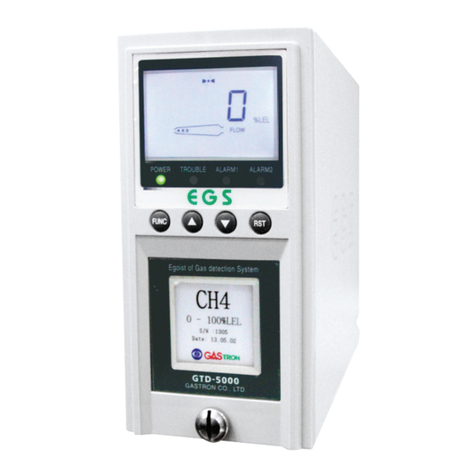
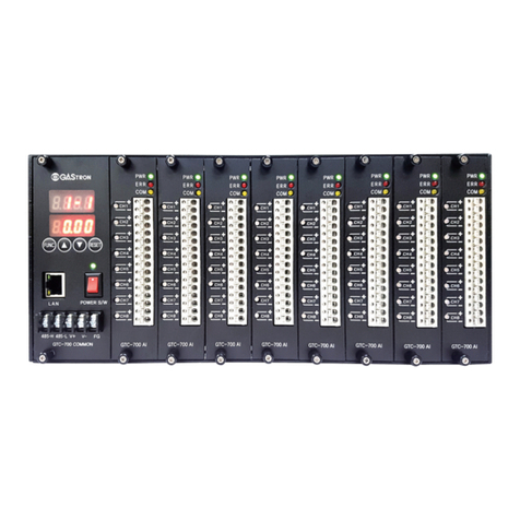
GASTRON GTC-200F Series User manual

GTC-200F
Instruction Manual
Headquarters / Engineering research laboratory :
23 Gunpo Advance d Industry 1-ro(Bugok-dong), Gunpo-si, Gyeonggi-do
Tel +82-31-490-0800 Fax +82-31-490-0801
Yeongnam business office / Plant :
55 Gonghangap-gil 85beon-gil, Gangseogu, Busan Metropolitan City
Tel +51-973-8518 Fax +51-973-8519
E-mail : [email protected]
www.gastron.com
Read in detail for correct use.

Gas & Flame
Detection System
GTC-200F
Instruction Manual
www.gastron.com
02_03
When abnormalities occur after purchasing the product,
please contact the following address.
·Address : 23 Gunpo Advanced Industry 1-ro,
Gunpo-si, Gyeonggi-do
·Tel : 031-490-0800
·Fax : 031-490-0801
·URL : www.gastron.com
·e-mail : [email protected]
We sincerely thank you for purchasing the product of Gastron Co. Ltd.
Our Gastron Co.Ltd. is a company specialized in Gas detector and Gas Monitoring System, being
recognized by many consumers due to the best quality and use convenience. We always enable you
consumers to find desired products nearby and are ceaselessly studying and striving for development
of Gas detectors satisfying customers. From now on, solve all anguishes concerning Gas detector with
the products of Gastron Co. Ltd, We Gastron Co. will take a responsibility and give you satisfaction.
In the present instruction manual, operation method for Gas detector as well as simple methods for
maintenance and repair, etc. are recorded If you read it in detail and keep it well, for reference when
you have questions, then it will give you much help.
* KOSHA GUIDE : P-135-2013
Calibration should be executed at periods required by the manufacturer, and should be executed in every quarter
unless there are separate calibration periods.
The present product and the product manual can be changed without advance notice for performance improvement and
use convenience of the product.
■ For accurate operation of Gas detector, check up and calibrate for more than once in every 6 months.
( * See No. 13 of KOSHA GUIDE : P-135-2013 / 8.3 paragraph on qualification and calibration)
■ For accurate operation of Gas detector, checkup and calibration with calibration gas before measurement
is recommended.
■
When not calibrated, it may cause malfunction of the equipment due to problems resulting from Sensor aging.
■ When the present instrument should be dismantled, those with professional skills for Gas detector should
conduct the operation.
■ For power supply cable, wire specifications should be determined by referring to the item of "Length of
installed cable".
■ For the contents on checkup and calibration of Gas detector, please use our company's engineering
department , e-mail, or web site.
Greetings

www.gastron.com
04_05
ContentsContents
GTC-200F
Instruction Manual
1. Overview ·························································································· 6
2. Features ··························································································· 6
3. Basic specifications ··············································································· 7
4. Specifications for channel card ···································································· 8
4.1. Common Alarm Unit ··········································································· 8
4.2. Channel Control Unit ·········································································· 9
4.3. Power Unit (Option) ··········································································· 9
5. Name and description of each part ································································ 10
5.1. Basic configuration and description ····························································· 10
5.2. Configuration and description of Power unit ····················································· 11
5.3. Configuration and description of warning unit (Common unit) ····································· 13
5.4. Configuration and description of concentration display unit(Channel unit) ·························· 15
6. Installation ························································································· 17
6.1. Separation of Cover ··········································································· 17
6.2. Power supply and signal configuration for Channel Unit ·········································· 17
6.3. Configuration of channel Unit terminal ·························································· 18
6.4. How to connect 3 wire type Gas detector ······················································· 19
6.5. How to connect 2 wire type Gas detector ······················································· 19
7. How to operate Power unit ········································································ 20
8. How to operate Common Unit ······································································ 21
8.1. Function ····················································································· 22
8.2. RS485 MODBUS Interface ····································································· 22
8.2.1. Communication setting ·································································· 22
8.2.2. RS485 MODBUS communication setting and Register ······································ 22
9. How to operate Channel Unit ······································································ 23
9.1. Power ON ···················································································· 23
9.2. Gas Measuring Mode ········································································· 23
9.3. Test Mode ··················································································· 24
9.4. Checkup mode (Stand-by Mode) ······························································ 24
9.5. Operation setting ············································································· 25
9.5.1. Program Mode ········································································· 25
9.6. ALARM Mode ················································································ 27
9.7. Maintenance Mode ··········································································· 29
10. Outline drawing and Dimensions ··································································· 31
10.1. Basic configuration ··········································································· 32
10.2. Power unit ··················································································· 32
10.3. Common Unit ················································································· 30
10.4. Channel Unit ················································································· 33
11. Notes before installation ··········································································· 34
11.1. Selection of installation place (Data from Occupational safety and health regulations) ················ 34
11.2. Selection of installation place (Data from safety management regulations on for high-pressure gas) ·· 34
11.3. Notes upon installation ········································································ 34
12. Revision record ···················································································· 36

www.gastron.com
06_07
GTC-200F
Instruction Manual
ITEMS SPECIFICATION
Input power supply AC 110V/220V 50/60Hz (Basic AC220V 50/60Hz)
Applicable specification for SMPS 24V 1.5A (24V 1.5A)
Alarm display Audio signal- Audible(Buzzer) and Visual signal- Visual(LED)
Alarm clearing Return switch- Manual (Reset switch)
Control input Outside pressure (Remote reset) - Buzzer stop/ return function
Measured output Isolation RS-485 modbus(Option)
Backup power unit(Option) 24V DC/600mA
24V DC/1300mA
Explosion-proof specification Explosion proof type (Ex d IIB T5) KCs
Approval CE, KR, KFI
Size 415(W)* 315(H) * 287(D) mm
Weight App. 30Kg
Operation Temperature -20 to 40 ℃
Storage Temperature -20 to 40 ℃
Operation Humidity 5 to 99% RH (Non-condensing)
Pressure Range 90 to 110KPa
GTC-200F Series is ammter with adoption of high-performance A/D Converter and Micro-Process, and has
diversified functions embedded. GTC200A Series is configured as a centralized type , being comprised of a Common
alarm unit and a Multi-Channel control unit, with the Multi channel control unit being connected to each detector.
GTC-200F Series is protected by a case of DIN Type, and has Wall mount type products with an explosion-proof
case. GTC-200F Series has FND Digital display (PV Value) function and 3-color LED Bar Graphic display (PV and
Alarm set value) embedded, with 3 Instant alarm functions(1st H/L, 2nd H/L, 3rdH/L) and breakdown alarm (Trouble
alarm).
GTC-200F Series has Audible(Buzzer) and Visual(Alarm LED and Bar graphic LED flashing) responses upon
occurrence of Instant alarm and Trouble alarm, with Max. PV Value holding functions upon occurrence of alarm.
GTC200A Series is capable of remote control for alarm clearing, and can perform interlocked control functions since it
has an output for alarms (SPDT Contact).
Common alarm unit of GTC200A Series is supplying communication output (Isolation type RS-485 : Option) to
configure Monitoring system such as Gas vision, etc. while each Channel control unit is supplying an output (4~20mA.
DC) for measured values.
GTC200A Series is configured with the latest parts, being equipped with stability and reliability, is capable of maximum
expansion (Max. 4channel) within a given space.
2. Features
1. Overview 3. Basic specications

www.gastron.com
08_09
GTC-200F
Instruction Manual 4. Specications for channel card4. Specications for channel card
4.1. Common Alarm Unit
ITEMS SPECIFICATION
Input form Analog 4-20mA
Measurement display 4-Digit FND and Bar-graph (32 segment, 3-color LED)
Measuring range 0.000 to 9999 Digital (Arbitrary setting by user)
Measurement accuracy FND Digital ±1% Full Scale
LED Bar ±1% Full Scale
Input measuring period 100 ms
Alarm setting 3-stage alarm(Arbitrary setting by user)
Alarm setting display 3 Color bar graphic (Green/Red/Yellow LED)
Alarm display LED bar graphic
Alarm clearing Manual (Common unit)
Self diagnosis Test switch and Reset switch
Control input/output RS-485
Measured output Analog 4-20mA
Alarm output
Breakdown alarm SPDT Relay dry contact signal output
Alarm 1 SPDT Relay dry contact signal output
Alarm 2 SPDT Relay dry contact signal output
Alarm 3 SPDT Relay dry contact signal output
Relay dry contact capacity : AC125V 10A
Operation power supply DC 24V / 100mA Max
4.2. Channel Control Unit
ITEMS SPECIFICATION
Input form RS-485
Input measuring period 100ms
Alarm display Audio signal- Audible(Buzzer) and Visual signal- Visual(LED)
Alarm clearing Return switch- Manual (Reset switch)
Control input Outside input(Remote reset) - Buzzer stop/return function
Measured output Isolation RS-485 modbus(Option)
Alarm output
Buzzer - Buzzer SPST Relay dry contact signal output
Breakdown alarm - SPDT Relay Dry contact signal output
1st alarm - Alarm 1 SPDT Relay dry contact signal output
2nd alarm - Alarm 2 SPDT Relay dry contact signal output
3rd alarm - Alarm 3 SPDT Relay dry contact signal output
Relay dry contact capacity : AC250V/3A, 30V/3A
Operation power supply DC 24V / 100mA Max
4.3. Power Unit (Option)
ITEMS SPECIFICATION
Input power supply DC. 24V
Output power supply DC. 24V (Reserve power supply : DC. 27V / 300mA)
Output power supply display FND Digital display
Main power supply display Green LED display
Reserve power supply display Green LED display
Reserve power supply monitoring Red LED display
Reserve power supply test Test switch for reserve power supply
Reserve power supply Ni-Cd Battery 24V / 600mA(less than 6 circuits)

www.gastron.com
10_11
GTC-200F
Instruction Manual 5. Name and description of each part5. Name and description of each part
[Figure 1. Alarm configuration and explanation]
5.1. Basic configuration and description
[Figure 2. Configuration of power supply unit]
5.2. Configuration and description of Power unit
[Table 1. Description of basic configuration]
NO NAME DESCRIPTIONS
8TEMPERED GLASS State of inside can be checked with 10mm of tempered glass.
9WRENCH BOLT Used for coupling of COVER and BODY. (M8x1.25 TAP, Length=53mm)
10 POWER SUPPLY Power supplied to COMMON and CHANNEL UNITS as well as GAS DETECTOR.
(Input AC110/220V, Output DC24V/3.5A)
11 TERMINAL PCB Power supply and each CHANNEL, Used for wire connection of detector
12 Internal ground (more than 2sq) Inside grounding is connected upon product release, while outside grounding is
connected by cable of more than 2sq after product mounting.
13 External ground (more than 2sq) Inside grounding is connected upon product release, while outside grounding is
connected by cable of more than 2sq after product mounting.
14 Cable Inlet (PF 3/4") Used for lead-in of power supply and signal cable, and designed to allow
connection of PF3/4" piping.
15 CASE fixing hole 4 ea. of 12mm holes machined to allow mounting of CASE.
16 Product Nameplate Simple note such as model name, explosion-proof class, etc. described
NO NAME DESCRIPTIONS
1GTC-200F CONTROL UNIT BODY Protects internal PCB, Power Supply, etc. from external environmental change and
impact.
2GTC-200F CONTROLUNIT COVER It is combined with CONTROL UNIT BODY. There is a glass part on the upper part to
check the current status.
3COMMON ALARM UNIT One to four channel units will sound an alarm when an alarm occurs, and will stop
and reset the buzzer.
4CHANNEL UNIT Indicates the concentration of connected GAS DETECTOR, usually 1~4 installed.
5ALARM LAMP It blinks when an alarm occurs and informs it visually.
6POWER SWITCH
Power ON / OFF.
(If you need to open the cover of the control unit, be sure to turn off the power before
performing the operation.)
7RESET BUTTON Release the alarm.

www.gastron.com
12_13
GTC-200F
Instruction Manual
NO NAME DESCRIPTIONS
1Front cover case Front-face Cover for Power Unit
2Main body case Main Body for Power Unit
3Acrylic Acryl for protection of front-face cover for Power Unit
4Front sub cover Front-face Sub cover for Power Unit
5Main body fixed bracket Bracket for mounting of Power Unit
6Main/Battery power display Main power voltage and battery voltage displayed. Voltages of power supplied to
Common unit and channel unit are displayed
7Main power LED When AC power supply is used. Main power supply LED is lighted, and it is turned
off when reserve power supply is used.
8Battery power LED When reserve power supply is used rather than AC main power supply, reserve
power supply LED is lighted.
9Battery power good LED Lighted when reserve power supply is connected and normal with voltage higher
than18V.
10 Battery power trouble LED Lighted when reserve power supply voltage is lower than 18V, and blinking when
reserve power supply is not connected.
11 Battery power test key
It is a switch for testing whether reserve power supply operates normally. When the
switch is pushed, voltage of the reserve power supply is applied to operate the gas
leakage alarm. At this time, voltage of the reserve power supply is displayed in FND.
12 Battery power ON/OFF switch
It is the on/off switch for reserve power supply.
Note1) It is turned off upon product shipment
Note2) Switch for the reserve power supply should be turned on after the main
power supply is turned on .
13 Front cover screw Screw for fixing of Power unit
14 Terminal PCB Power Unit Terminal PCB
15 Terminal PCB screw Screw for fixing of Power Unit Terminal PCB
16 DC input connector Inputting connector for Power supply of Power Unit
17 Battery connector Inputting connector for reserve power supply of Power Unit
18 DC output connector Power supply output connector for operation of channel card
NO NAME DESCRIPTIONS
1Front cover case Front-face Cover for Common unit
2Main body case Front-face main Body for Common unit
3Acrylic Acryl for protection of front-face cover for Front-face main Body for Common unit
4Front SUB cover Front-face Sub cover for Common unit
5Main body fixed bracket Bracket for mounting of Common unit
6Buzzer Operating with intermittent sound of each upon occurrence of Alarm and Trouble in
each Channel
7Power LED Power LED is lighted when power is inputted in Common unit
8Trouble LED Trouble LED is lighted upon occurrence of Trouble in each Channel Unit.
Ex) Upon occurrence of defective wire connection with detector and of abnormality
9Alarm-3 LED
Alarm 3 LED is lighted upon occurrence of the 3rd alarm in each Channel unit.
Alarm 3 LED is lighted when the 3rd alarm value is reached upon execution of test
function in each channel
10 Alarm-2 LED
Alarm 2 LED is lighted upon occurrence of the 2nd alarm in each Channel unit.
Alarm 2 LED is lighted when the 2nd alarm value is reached upon execution of test
function in each channe
[Table 2. Description on configuration of power supply unit]
[Figure 3. Configuration and description of alarm unit]
5.3. Configuration and description of alarm unit (Common unit)
5. Name and description of each part5. Name and description of each part

www.gastron.com
14_15
GTC-200F
Instruction Manual
NO NAME DESCRIPTIONS
11 Alarm-1 LED
Alarm 1 LED is lighted upon occurrence of the 1st alarm in each Channel unit. Alarm
1 LED is lighted when the 1st alarm value is reached upon execution of test function
in each channel
12 Communication LED (Channel)
When normal communication is realized with entire channel units set in the channel
unit COM-CH LED continues to be lighted, while COM-CH LED blinks if there is a
channel unit without realization of communication.
(When the No. of Channel units is set as less than 1 ea. In common unit, it blinks at
an interval of 0.5 sec.)
13 Communication LED (PC)
When communication DATA transmitted from PC is normally received in common
unit, COM-PC LED is immediately turned off after being lighted once..
(When the No. of Common unit addresses is set as less than 1 ea. In common unit,
it blinks at an interval of 0.5sec.)
14 Buzzer stop LED
As the Alarm occurs in channel unit, buzzer operates. When Buzzer stop is pushed,
the buzzer is stopped, at this time BZ-STOP LED is lighted. When the Buzzer stop
is pushed once more in Common unit or Channel unit, BZ-STOP LED is turned Off.
(However, it is lighted only when Alarm type was set for hold in the channel unit)
15 Buzzer Stop/Reset key
It is a key used for Buzzer stop and Reset upon occurrence of trouble and alarms in
each channel unit.
Push once initially.... Buzzer sound is stopped and BZ-STOP LED is lighted.
Push twice consecutively.... BZ-STOP LED is turned Off, and Reset function of all
Channel units in Latch state according to Alarm setting is executed.
16 Power ON/OFF switch Power ON/OFF switch of Common unit
17 Front cover screw Screw for fixing of Common unit
18 Terminal PCB Common Unit Terminal PCB
19 Terminal PCB screw Screw for fixing of Common Unit Terminal PCB
20 Connector Input connector for signals
[Table 3. Description on configuration of alarm unit]
NO NAME DESCRIPTIONS
1Front cover case Front-face Cover for Channel control unit
2Main body case Main Body for Channel control unit
3Acrylic Acryl for protection of front-face cover for Channel control unit
4Front sub cover Front-face Sub cover for Channel control unit
5Main body fixed bracket Bracket for mounting of Channel control unit
6FND display
Measured values of the detector connected to each channel continues to be
displayed, while user designated value is displayed in blinking state upon execution
of test function.
7Power LED When Power is inputted in channel unit, Power LED is lighted.
8Checkup LED STD-BY LED blinks when it is in checkup mode for detector.
9Trouble LED Trouble LED is lighted upon occurrence of trouble in channel unit and detection unit.
Ex) Upon occurrence of defective wire connection with detector and of abnormality
10 Alarm-3 LED
Upon occurrence of the 3rd alarm in channel unit, Alarm 3 LED is lighted. Alarm 3
LED is lighted when the 3rd alarm value is reached upon execution of test function in
the channel unit.
[Figure 4. Components of concentration display unit]
5.4. Configuration and description of concentration display unit (Channel unit)
5. Name and description of each part5. Name and description of each part

www.gastron.com
16_17
GTC-200F
Instruction Manual
NO NAME DESCRIPTIONS
11 Alarm-2 LED
Upon occurrence of the 2nd alarm in channel unit, Alarm 2 LED is lighted. Alarm 2
LED is lighted when the 2nd alarm value is reached upon execution of test function
in the channel unit.
12 Alarm-1 LED
Upon occurrence of the 1st alarm in channel unit, Alarm 1 LED is lighted. Alarm 1
LED is lighted when the 1st alarm value is reached upon execution of test function in
the channel unit.
13 3 color bar graphic LED
3 Color bar graphic LED continues to display measured values and alarm setting
values together with FND display. Bar graphic LED is lighted in green when the
measured value is less than the 1st Alarm, in orange when it is more than the 1st Alarm
and less than the 2nd Alarm, and in red when it is more than the 2nd Alarm.
When the measured value is more than the alarm setting value, Bar graphic is held at
the maximum value, and Bar graphic is displayed in blinking state for the alarm.
14 Reset key Functions of Channel unit such as Alarm clearing, Self test clearing, Program setting
clearing, etc. are performed.
15 Down key
Arbitrary values can be selected by using "▲", "▼" Keys after each mode is selected
with Func. Key. When "▲", "▼" Key is being pushed for a given time in the mode
requiring many changes in setting value, the setting values are changed fast,
16 Test key
When Test switch is pushed, the mode of executing self-diagnosis function is
entered into.
It is a key where the measured value FND blinks, and Alarm operation state can be
checked in Channel unit and Common unit by using "▲", "▼" Key to adjust measured
values that are blinking.
Diagnosis is cleared by pushing once of the Reset key in each channel.
17 Function key
Function key is a key where Data values are inputted by conversion and selection of
functions such as setting of alarm values, setting of alarm methods, setting of Dead
band and of delay operation for alarm , etc.
18 Up key
Arbitrary values can be selected by using "▲", "▼" Keys after each mode is selected
with Func. Key. When "▲", "▼" Key is being pushed for a given time in the mode
requiring many changes in setting value, the setting values are changed fast,
19 Power ON/OFF switch Power ON/OFF switch for Channel unit.
20 Front cover screw Screw for mounting of Channel unit
21 Terminal PCB Channel Unit Terminal PCB
22 Terminal PCB screw Screw for mounting of Channel Unit Terminal PC
23 Connector Output connector for signals
6. Installation
[Table 4. Description of density display component]
6.1. Separation of Cover
■ Unfasten 14 places displayed by arrows in the above figure by
using a 6mm hexagonal Wrench.
■ (Caution) No one other than approved users or those of
the headquarters in charge of installation and repair should never
been allowed to install in the field or open or operate the cover for
the installed Control Unit. Otherwise, serious damages to life and
property such as fire or explosion accidents may be inflicted.
■ (Caution ) Make sure to shut off power supply for operation after
checking whether any explosive GAS remains or there is any
flammable substance in the surroundings.
6.2. Power supply and signal configuration for Channel Unit
■ Configurations for channel Unit, Common Unit and power Unit are as shown in the following figure with
the channel Unit allowing the maximum configuration of 63 ea.
■ The power unit is installed only when the battery is used.
■ When not using the power unit, connect DC24V directly to the connector (CN6) of the common unit in the power
supply. (Power unit is optional.)
[Figure 5. Separation of Cover]
[Figure 6. Power supply and signal configuration for Channel Unit]
5. Name and description of each part

www.gastron.com
18_19
GTC-200F
Instruction Manual 6. Installation6. Installation
6.3. Configuration of channel Unit terminals
[Figure 7. Configuration of
Channel Unit terminal]
NO TERMINAL CONFIGURATION DESCRIPTION
1Output 4-20mA + 4-20mA output of measure values of detection unit
2Output 4-20mA -
3TROUBLE RELAY NO
Output Relay for breakdown state4TROUBLE RELAY NC
5TROUBLE RELAY COM
6Alarm3 RELAY NO
Output Relay for 3rd alarm7Alarm3 RELAY NC
8Alarm3 RELAY COM
9Alarm2 RELAY NO
Output Relay for 2nd alarm10 Alarm2 RELAY NC
11 Alarm2 RELAY COM
12 Alarm1 RELAY NO
Output Relay for 1st alarm13 Alarm1 RELAY NC
14 Alarm1 RELAY COM
15 Power supply for detector + Supply power to detection unit and
input 4-20mA signals
16 4-20mA input for detector
17 Power supply for detector -
6.4. Connection method of 3-wire type for Gas detector
■ When the gas detector is configured with power supply and 4-20mA output using 3 wires(V+, mA, V- ),
connect to the channel unit by the following method.
■ Connection cable should be configured with shield cable of CVVS or CVVSB of more than1.5sq.
[Figure 8. 3-wire connection method for gas detector]
■ Our company's detector models of the relevant method include TS-1100Ex, TS-2000Ex, TS-2100 Series,
TS-4000 Series, TS-4100P Series, TS-5100 Series, GTD-1000 Series, GTD-2000 Series, GTD-3000 Series,
and GIR-3000 Series.
6.5. Connection method of 2-wire type for Gas detector
■
When output of gas detector is configured using 2-wires(V+, V- ), connect to the channel unit by the following method.
■ nection cable should be configured with shield cable of CVVS or CVVSB of more than1.5sq.
■ Our company's detector models of the relevant method include TS-1100Tx, TS-2000Tx, TS-3000 Series, and
TS-3100 Series.
[Figure 9. 2-wire connection method for gas detector]

www.gastron.com
20_21
GTC-200F
Instruction Manual
8.1. Functions
■ Voltage of main power supply is displayed in FND Digital display s figures.
■ When the checkup key for reserve power supply is pushed, the power supply is
converted to the reserve power supply, with voltage of the reserve power supply
being displayed in FND Digital display as figures.
■ When reserve power supply is not connected, breakdown LED for reserve power
supply blinks at an interval of 0.5 sec.
■ When the reserve power supply is more than 18V, normal LED for reserve power
supply is lighted, while breakdown LED for reserve power supply is lighted when it is
less than 18V.
Note1) It is turned off upon product shipment.
Note2) Turn on the switch for reserve power supply after the main power supply is
turned on.
NO FUNCTION DESCRIPTION
1Buzzer alarm
When a breakdown signal is sent from the Channel unit, alarm sound occurs as a short
intermittent sound.
When alarm signal is sent from the Chanel unit, alarm sound occurs as a long intermittent
sound.
2Breakdown/Alarm LED LED lighted when breakdown signal or alarm signal occurs in the Channel unit, with the
alarm LED blinking during alarm maintenance time.
3Communication LED
COM-CH LED displays communication state between Common unit and Channel unit, and
is turned off after being lighted for about 0.1 sec upon communication for once. Thus, the
continuously lighted state is maintained when normal communication occurs as many as the
No. of Channel units set in the Common unit (Channel unit access time is 0.1sec).
When communication DATA transmitted from PC is normally received in Common unit,
COM- PC LED is immediately turned OFF by being lighted once.
When SW1 and SW2 are set to be less than 1 ea. In Common unit, blinking occurs at an
interval of 0.5sec(COM-CH/ COM-PC LED).
4Buzzer-Stop LED
As an alarm occurs in Channel unit, the buzzer operates. The buzzer is stopped when
Buzzer stop switch is pushed, at which time BZ-STOP LED is lighted (However, it is lighted
only when Alarm type was set for hold in Channel unit).
When the Buzzer stop is pushed once more in Common unit or channel unit, BZ-STOP LED
is turned Off.
5Buzzer stop and Reset key
A Key used for Buzzer Stop and Reset when Trouble and Alarm occurs in each Channel unit
Push once initially.... Buzzer sound is stopped and BZ-STOP LED is lighted.
Push twice consecutively.... BZ-STOP LED is turned Off and Reset function of all channel
units in latch state according to Alarm setting is executed.
8. How to operate Common Unit7. How to operate Power unit
Reserve power
supply switch

www.gastron.com
22_23
GTC-200F
Instruction Manual
8.2.1. Setting for communication
8.2. RS485 MODBUS Interface 9.1. Power ON
■ Baud rate : 9600BPS
■ Stop bit : 1 Stop
■ Parity : Even parity
■ Check wire connection of operation power supply, wire connection with detection unit, wire connection between
alarm unit and concentration display unit, etc.
■ Turn ON the power supply switch after checking input power supply.
■ Check lighting of Power LED for alarm unit and concentration display unit.
■ Check display of "SELF" in FND for concentration display unit.
8.2.2. Setting for RS485 MODBUS communication and Register
NO FUNCTION NAME ADDRESS OTHER
1Concentration value for Channel-1 unit 30001 Address increased by 1
at a time per Channel unit.
2Concentration value for Channel-2 unit 30002
3Concentration value for Channel-n unit 30xxx
■ Concentration values for Channel unit (Analog input)
[Table 5. Register of concentration values for channel Unit RS485]
NO FUNCTION NAME ADDRESS OTHER
Channel-1 unit
Alarm1 state data 10001
8Bit each assigned per 1
Channel unit
Alarm2 state data 10002
Alarm3 state data 10003
Breakdown state data 10004
Checkup state data 10005
Reserve data 10006~10008
Channel-2 unit
Alarm1 state data 10009
8Bit each assigned per 1
Channel unit
Alarm2 state data 10010
Alarm3 state data 10011
Breakdown state data 10012
Checkup state data 10013
Reserve data 10014~10016
Channel-n unit State data 10001+((n-1)*8) ~ 10001+(((n-1)*8)+8)
■ Bit data for Channel unit state ( Reading data for digital input contact)
[Table 6. Register of channel Unit RS485 state]
9.2. Gas Measuring Mode
■
If there is no abnormality in SELF TEST after Power On, the following gas measuring state is automatically entered into.
- When power supply for Channel unit is turned ON, "SELF" in FND for concentration display unit blinks
for 15 Sec, and immediately becomes measuring state when Warming-Up is finished.
- If abnormality occurs in equipment and detection unit at this time, breakdown alarm occurs
- Gas concentration values received from the detector are displayed in FND Digital display as figures.
- The gas concentration is also displayed by 3 Color Bar graphic LED, in green for the concentrations
of less than 1st Alarm , in orange for the concentrations of more than 1st Alarm but less than 2nd
Alarm, and in red for the concentrations of more than 2nd Alarm.
- 3-stage Alarm setting values are constantly displayed by 3 Color bar graphic LED, in green for 1st
Alarm values, in orange for 2nd Alarm values, and in red for 3rd Alarm values.
- When the detector is not connected or has abnormalities, the text of "Undr" is displayed by blinking at
an interval of about 0.5sec.
- Trouble LED lamp is lighted.
- The circular LED at the bottommost among 3 Color bar graphic LED's is lighted in red
- When the current value inputted from the detector is inputted as a current value of more than the set
High Scale value by 10%, the text of "Ouer" is displayed by blinking at an interval of 0.5 sec.
- The circular LED at the topmost among 3 Color bar graphic LED's is lighted in red..
- When the gas concentration value is recognized as being more than the Alarm setting value, Alarm
function is operated as the relevant Alarm function counts the Alarm maintenance time to find it to be
more than the Alarm maintenance time.
- While the Alarm maintenance time is being counted, Alarm LED Lamp blinks at an interval of 0.5sec,
and lighted when it becomes more than the Alarm maintenance time.
- Alarm relay is turned ON when it becomes more than the Alarm maintenance time.
- When Alarm latch type is in "on" mode, Alarm state and gas concentration value are maintained at the
maximum value upon operation of Alarm function, is not cleared even when the gas concentration is
lowered below the Alarm value, in which case, it must be cleared by using "Reset" key.
- When the Alarm latch type is in "off" mode, Alarm function is automatically cleared depending on gas
concentrations
9. How to operate Channel Unit8. How to operate Common Unit

www.gastron.com
24_25
GTC-200F
Instruction Manual
9.5. Setting for operation
9.5.1. PROGRAM MODE
9.3. Test Mode
■
If there is no abnormality in SELF TEST after Power On, the following gas measuring state is automatically entered into.
- When "▲", "▼" keys are simultaneously pushed in the display state for gas concentration, the setting
function for program data is entered into.
- In the program setting function, the display state for gas concentration is automatically returned to
when 10 sec passed after the last key operation in the program setting function.
- The message for setting of decimal point as the 1st function of setting function for program data is
displayed as "dP-S".
- When "Func" key is pushed, the setting function for decimal point is entered into.
- When "Reset" key is pushed, the concentration display mode is returned to.
- Decimal point is used when there is a need to change according to measuring range. When position
of the decimal point is set, the position of the decimal point is changed in 3 ways as shown on the left
whenever "▲" key or "▼" key is pushed.
- If "FUNC" key is pushed when the desired position of decimal point is displayed, the decimal point
position is set and the next item is entered into.
- When "Reset" key is pushed, the concentration display mode is returned to.
- The message for setting function of High scale as a function for setting the maximum value of gas
concentration display is displayed as "H-SL".
- When "Func" key is pushed, the setting function for High scale is entered into.
- When "Reset" key is pushed, the concentration display mode is returned to.
- High scale value is set for the range specified by domestic regulations upon product shipment.
- The setting value for High scale can be changed according to measuring range, and the Scale value
is increased or decreased whenever "▲" key or "▼" key is pushed.
- If "FUNC" key is pushed when the desired High scale value is displayed, the High scale value is set,
and the next item is entered into.
- When "Reset" key is pushed, the concentration display mode is returned to.
- The present setting mode shall be set for the same measuring range as the detection unit upon
factory shipment. Ex) When Range setting was made to be 100
Upon inputting of 4 mA.DC ................... 0 Display
Upon inputting of 20 mA. DC ................... 100 Display
- When "Test" key is pushed for more than 2sec in the display state of gas concentration, Test mode
is entered into.
-
When 30 min is passed after the last key operation in Test mode, the display state of gas concentration
is automatically entered into.
- Upon entering in Test mode, the displayed figure for gas concentration is displayed by blinking,
where this function allows test in Channel unit without injection of sensor gas in the detector. When
the user pushes "▲" key or "▼" key , an arbitrary concentration value for gas concentration can be
set, while Alarm function is normally operated with the concentration value designated by sec, FND/
LED/Bar LED test function is entered into.
- When "Reset" key is pushed, the concentration display mode is returned to.
- FND/LED/Bar LED Test mode where FND figure of 4 digits and the entire display (8888) are displayed
at an interval of 0.5sec, with the 4-digit figure displaying the setting values for PC Add(SW1) and CH
CNT(SW2) of Common unit.
- 3 Color bar graphic LED displays green, orange and red colors alternatingly at an interval of 0.5sec
with each function LED blinking at an interval of 0.5sec.
- When "Func" key is pushed, the mode for checking Channel unit with normal operation of Common
unit and communication is entered into.
- When "Reset" key is pushed, the concentration display mode is returned to.
- Mode for checking of Channel unit with normal operation of Common unit and communication,
where the No. of channel unit with normal communication being realized is sequentially displayed at
an interval of 0.5sec .
- If there is a No. for Channel unit where all of the number of channel units set in common unit is not
displayed but omitted, then it becomes the channel unit without communication.
- When "Func" key is pushed, Test function for gas concentration is returned to.
- When "Reset" key is pushed, the concentration display mode is returned to.
9.4. Checkup mode (Stand-by Mode)
- When "▼(Standby)" key of channel unit is pushed for more than 2sec in the display state for gas
concentration, checkup mode is entered into.
- In the checkup mode, the checkup mode is cleared and the display state for gas concentration is
returned to when"▼(Standby)" key is surely pushed in channel unit,
- The function where STD-BY LED blinks inn checkup mode, and contact output of Trouble/Alarm
relay for Common unit and Channel unit의 Trouble/Alarm relay does not operate with all remaining
functions in operation.
- When "▼(Standby)" is pushed, the concentration display mode is returned to.
▼ ▲
9. How to operate Channel Unit9. How to operate Channel Unit

www.gastron.com
26_27
GTC-200F
Instruction Manual
- The message for setting function of SAD values as a function to compensated for errors in measured
values occurring in detection unit is displayed as "SAd ".
- When "Func" key is pushed, the setting function for SAD value is entered into.
- When "Reset" key is pushed, the concentration display mode is entered into.
- Function for setting of SAD value, and SAD value is increased or decreased whenever "▲" key or
"▼" key is pushed.
- If "FUNC" key is pushed when the desired SAD value is displayed, SAD value is set and the next item
is entered into.
- When "Reset" key is pushed, the concentration display mode is returned to.
Ex) When SAD was set as 2 :When the output error in detector is -2, Display calibrates the SAD
setting value 2 and displays it as 0 although actual Display should indicate -2.
- The message for setting function of Channel number as a function for setting the recognition No. for
Channel unit is displayed as "CHno ".
- When "Func" key is pushed, the setting function for Channel number is entered into.
- When "Reset" key is pushed, the concentration display mode is returned to.
- Channel No. is a mode where Channel unit address is inputted to allow checking of operation
situations for each channel in Common unit, and Address NO. value is increased or decreased
whenever "▲" key or "▼" key is pushed. .
- If "FUNC" key is pushed when the desired Address NO is displayed, the Address NO value is set and
Alarm reset type function as the next item is entered into..
- When "Reset" key is pushed, the concentration display mode is returned to.
Note 1) Unless the Channel No.is inputted, communication between Channel unit and common unit
does not occur.
Note2) For Channel No, mutually different Nos. must be inputted.
9.6. ALARM Mode
■ When "Func" key is pushed for more than 2 sec in the display state of gas concentration, the setting function for
alarm value data is entered into.
■ When10 sec passes after the last key operation in the setting function for alarm value, the display state of gas
concentration is automatically returned to.
- The message for setting function of Alarm latch type as a function for setting of Alarm latch type is
displayed as "LACH".
- When "Reset" key is pushed, the concentration display mode is returned to.
- Mode for change of Alarm reset type, and "on" and "oFF" modes are changed whenever "▲" key or
"▼" key is pushed .
- If "FUNC" key is pushed when the desired Alarm latch type is displayed. the Alarm latch type is set
and the next item is entered into.
- Alarm latch type has 2 types of "on" and "oFF" OFF where Alarm is automatically Reset in OFF mode,
while Alarm is Reset in on mode when the user surely clears by pushing Reset key.
- The message for setting function of Alarm 1 value as a function for setting of Alarm1 value is
displayed as "AL-1".
- When "Func" key is pushed, the setting function for Alarm1 value is entered into.
- When "RESET" key is pushed, the concentration display mode is returned to.
- Alarm level is set for the concentration specified by domestic regulations upon product shipment.
- Function for change of Alarm1 setting value, where the maximum value is possible up to the High
scale value, and the Alarm1 value is increased or decreased "whenever "▲" key or "▼" key is pushed.
- If "FUNC" key is pushed when the desired Alarm1 value is displayed, the Alarm1 value is set and the
next item is entered into.
- When "Reset" key is pushed, the concentration display mode is returned to.
- Mode for setting of the operation direction of Alarm1, "1H " or "1L " is displayed whenever "▲" key or
"▼" key is pushed.
-
"1H " mode is the mode operating when it is larger than or the same as Alarm1setting value, while "1L "
mode is the mode when it is smaller than or the same as Alarm1setting value.
- If "FUNC" key is pushed when the desired mode is displayed, the mode is set and the next item is
entered into.
- When "Reset" key is pushed, the concentration display mode is returned to.
- Alarm type is set for flammability: 1H and 2H and 3H / oxygen: 3H and 2L and 1L / toxicity: 1H and
2H and 3H Type upon factory shipment.
▼ ▲
Full Range
9. How to operate Channel Unit9. How to operate Channel Unit

www.gastron.com
28_29
GTC-200F
Instruction Manual
- The message for setting function of Alarm1 blink output as a function for setting the function of ON/
OFF of Alarm1 contact output at an interval of 1 sec while buzzer is operating is displayed as "A1bL".
- When "Func" key is pushed, the setting function for Alarm1 blink output is entered into.
- When "RESET" key is pushed, the concentration display mode is returned to.
- Mode for change of Alarm1 blink output, "on" and "oFF" modes are changed whenever "▲" key or
"▼" key is pushed.
- If "FUNC" key is pushed when the desired Alarm1 blink outmode is displayed, the Alarm1 blink output
mode is set and the next item is entered into.
- When "RESET" key is pushed, the concentration display mode is returned to.
- Alarm1 blink output mode has 2 types of " on" and " oFF" , where Alarm1 blink output does not operate
in oFF mode while Alarm1 blink output is operated in on mode.(However, it operates when the Alarm1
contact output mode is on.
- Both the 2nd alarm (Alarm2) and the 3rd alarm (Alarm3) have the same menu structure.
- The message informing completion of the setting function is displayed as "End" for 2 sec, and
the display state of gas concentration is returned to.
-
Mode for setting of Dead band value with operation of Alarm1, and the value is increased or decreased
whenever "▲" key or ▼" key is pushed.
- Function where Alarm1operates above Alarm value plus Dead band value when the Alarm1 is in "1H "
mode while Alarm1 is cleared below Alarm value minus Dead band value.
- Function where Alarm1 operates below Alarm value minus Dead band value when Alarm1 is in "1L "
mode while Alarm 1 is cleared above Alarm 1 1 value plus Dead band value.
- If "FUNC" key is pushed when the desired Alarm1 Dead band value is displayed, the value is set and
the next item is entered into.
- When "Reset" key is pushed, the concentration display mode is returned to.
- In this function, Alarm continues On/Off when the concentration value reaches near the Alarm setting
value. It is the function of giving hysteresis value to remove such phenomenon, and the value is set
for 0 upon factory shipment.
Ex) When the alarm setting value is 20%LEL / Dead band: 2%LEL, the alarm occurs at 22% LEL
based on 20%LEL, and is cleared at18%LEL.
- The message for setting function of Alarm1 delay time as a function for setting of Alarm1 delay time is
displayed as "AL1t".
- When "Func" key is pushed, the setting function for Alarm1 delay time is entered into.
- When "RESET" key is pushed, the concentration display mode is returned to.
- Function to prevent occurrence of instantaneous malfunction of detector due to effects of external
impact and noise rather than normal operation, and Alarm1 delay time is increased or decreased by
the unit of sec whenever "▲" key or "▼" key is pushed.
- If "FUNC" key is pushed when the desired Alarm1 delay time is displayed, the Alarm1 delay time is
set and the next item is entered into.
Ex) When alarm setting value: 20% LEL / Delay time: 5 Sec, alarm occurs based on 20%LEL when
the measured value above the alarm setting value for more than 5sec, while alarm does not occur
when it falls below the alarm setting value within 5 Sec.
- The message for setting function of Alarm1 contact output as a function for setting of Alarm1 contact
output is displayed as "A1rl".
- When "RESET" key is pushed, the concentration display mode is returned to.
-
Mode for change of Alarm1 contact output, and "on" and "oFF" modes are changed whenever "▲" key
or "▼" key is pushed.
- If "FUNC" key is pushed when the desired Alarm1 contact output mode is displayed, the Alarm1
contact output mode is set and the next item is entered into.
- When "RESET" key is pushed, the concentration display mode is returned to.
- Alarm1 contact output mode has 2 modes of "on" and "oFF" , where Alarm1contact output does not
operate in oFF mode while Alarm1 contact output operates in on mode.
▼ ▲
- If "TEST" and "RESET" keys are simultaneously pushed when "SELF" is blinking after power supply ON,
the setting function for Maintenance is entered into.
- When "Reset" key is surely pushed in Maintenance mode, the display state for gas concentration is
returned to.
- Mode for selection of functions setting current input value and output value as the reference for Alarm
Channel unit , and "-In-" or "-oUt" is displayed whenever "▲" key or "▼" key is pushed.
- If "FUNC" key is pushed when the desired mode is displayed, the relevant mode is entered into.
- When "-In-" is selected, it is the mode for setting of current input values, while it is the mode for
setting of current output values when "-oUt" is selected.
- When "Reset" key is pushed, the concentration display mode is returned to.
- Mode for setting by inputting the current of 20mA in the case of having selected "-In-", and the
message is displayed as "IA20".
- When "Func" key is pushed, the function with the current input value being displayed as figures is
entered into.
- When "Reset" key is pushed, the concentration display mode is returned to.
9.7. Maintenance Mode
■ Both the 2nd alarm and the 3rd alarm have the same menu structure.
9. How to operate Channel Unit9. How to operate Channel Unit

www.gastron.com
30_31
GTC-200F
Instruction Manual
- Mode where the values converted in processor by inputting 20mA current in (mA) terminal are
displayed as figures.
- If "Func" key is pushed when the displayed figure is stable, the current input value is set and the next
item is entered into.
- When "Reset" key is pushed, the concentration display mode is returned to.
-
Mode for setting output current of 4mA when "-Out" was selected the next mode for input current mode,
and the message is displayed as "A-04".
- If "Func" key is pushed when the ammeter accurately displays 4mA by pushing "▲" key or "▼" key
while watching the ammeter after connecting the ammeter to 4~20mA output terminal, the output
current value is set and the next item is entered into.
- When "Reset" key is pushed, the concentration display mode is returned to.
- Mode setting for 20mA output current with the message being displayed as "A-20".
- If "Func" is pushed when the ammeter accurately displays 20mA by pushing "▲" key or "▼" key while
watching the ammeter after connecting the ammeter to 4~20mA output terminal, the output current
value is set and the next item is entered into.
- When "Reset" key is pushed, the concentration display mode is returned to.
- The message informing completion of the setting function is displayed as "End" for 2 sec, and
the display state of gas concentration is returned to.
10.1. Basic configuration
[Figure 10. Outline drawing for basic product]
10. Outline drawing and Dimensions9. How to operate Channel Unit

www.gastron.com
32_33
GTC-200F
Instruction Manual
10.4. Channel Unit10.2. Power unit
10.3. Common Unit [Figure 13. Outline drawing for Channel Unit]
[Figure 11. Outline drawing for Channel Unit]
[Figure 12. Outline drawing for Common Unit]
10. Outline drawing and Dimensions10. Outline drawing and Dimensions

www.gastron.com
34_35
GTC-200F
Instruction Manual
11.1. Selection of installation place (Data from Occupational Safety and Health regulations)
The place for installation of gas leakage detection alarm is as follows.
■ Surroundings of chemical equipment and accessory equipment with a risk of gas leakage such as compressor,
valve, reactor, piping connection part, etc. that are installed inside and outside buildings to deal with flammable
and toxic substances
■
Place with easy dwelling of gas around manufacturing equipment with ignition sources such as heating furnace, etc.
■ Around the connecting part for filling of flammable and toxic substances
■ Power substation, power distribution panel room, control room, etc. positioned within explosion-proof area
■ Other places with especially easy dwelling of gas
11.2. Selection of installation place(Data from regulations on safety management for high-pressure gas)
Gas detector for has leakage detection alarm should be installed as close as possible to leakage parts with a risk
of gas leakage. However, for the places with likelihood of dwelling of gas leaked from surroundings although direct
gas leakage is not expected, installation should be implemented at spots such as No.1 of the following list.
■ Gas leakage detection alarm installed outside a building shall be installed at a spot with dwelling likelihood of gas
by considering wind direction, wind velocity ,specific gravity of gas, etc.
■ Gas leakage detection alarm installed inside a building should be installed in the lower part inside the building
when specific gravity of the detection target gas is larger than that of air, while it should be installed near
ventilation port of the building or in the upper part inside the building when it is lighter than air.
■ Alarm of Gas leakage detection alarm should be installed at a place with installation of Gas detector and a place
of constant residence of workers
11.3. Notes upon installation
Positions that can be an electric obstacle such as rain water, etc. should be avoided for installation, and installation at
a place for easy operation is recommended since periodic maintenance and repair are. Since the places with vibration
or impact can affect output values, places with vibration or impact shall be avoided for installation, and installation shall
be such that the sensor unit is facing the direction of gravity.
■
The present instrument shall belong to the GROUP aimed at gas, vapor of general business places and chemical
plants as a pressure-resistant, explosion-proof structure, and can be used for dangerous places of ZONE 1(ONE)
-type 1 and ZONE 2(TWO)-type 2.
■
Allowed temperatures belong to less than 85℃ corresponding to T6.
■
It shall be used in the range of -20℃ ~ 40℃ for ambient temperature
■
Installation altitude: Less than 1,000M above sea level
■
Relative humidity: 5% ~ 99%
■
Installation place: Outdoors and indoors
■
Explosion and ignition level of target gas or vapor: Ex d IIC T6Positions that can be an electric obstacle
■
When explosion-proof cable gland is used in cable lead-in port or metal cable conduit wiring construction is conducted,
cable conduit should be sealed to prevent moving of gas, etc. through cable conduit within 50mm or propagation of
flames upon explosion.
■
Upon connection of the present instrument and cable conduit, more than 5 threads should be made to be coupled.
■
Conduct operation under the conditions meeting other [Standards related to selection, installation and repair, etc. of
explosion-proof structure, electricity, machine, apparatus, wiring, etc. of business place].
■
For all materials used for cable lead-in such as CABLE GLAND and SEALING FITTING, etc. as well as materials used
for finishing of the unused lead-in unit, make sure to sue products having passed qualification!
11. Notes before installation11. Notes before installation
[Figure 14. Pressure-resistant packing] [Figure 15. Y Sealing Compound]
Cable Cable
Inside Inside
Outside Outside
Lead-in unit connector
Lead-in unit connector
Charging compound
Cable-fixing device
Pipe for piping
Cable-fixing device
Sealing ring
Sealing
ring
Connector
Pipe for piping
Compressed
element
Connector for fixing
compressed element

www.gastron.com
36_37
GTC-200F
Instruction Manual
VERSION CONTENTS DAT E
0.0 Manual initially revised 2011. 06. 27
1.0 Font changed 2016. 10. 28
2.0 Installation regulation for Cable Entry in explosion-proof instrument changed 45cm → 50mm 2017. 01. 20
12. Revision record
Table of contents
Other GASTRON Measuring Instrument manuals
