Vega VEGACAP 35 User manual

Operating Instructions
Capacitive cable electrode for level
detection
VEGACAP 35
Relay (DPDT)
Document ID: 33759

2
Contents
VEGACAP 35 • Relay (DPDT)
33759-EN-230510
Contents
1 About this document ............................................................................................................... 3
1.1 Function ........................................................................................................................... 3
1.2 Target group ..................................................................................................................... 3
1.3 Symbols used................................................................................................................... 3
2 For your safety ......................................................................................................................... 4
2.1 Authorised personnel ....................................................................................................... 4
2.2 Appropriate use................................................................................................................ 4
2.3 Warning about incorrect use............................................................................................. 4
2.4 General safety instructions............................................................................................... 4
2.5 Conformity........................................................................................................................ 5
2.6 Installation and operation in the USA and Canada ........................................................... 5
2.7 Safety instructions for Ex areas ........................................................................................ 5
2.8 Environmental instructions ............................................................................................... 5
3 Product description ................................................................................................................. 6
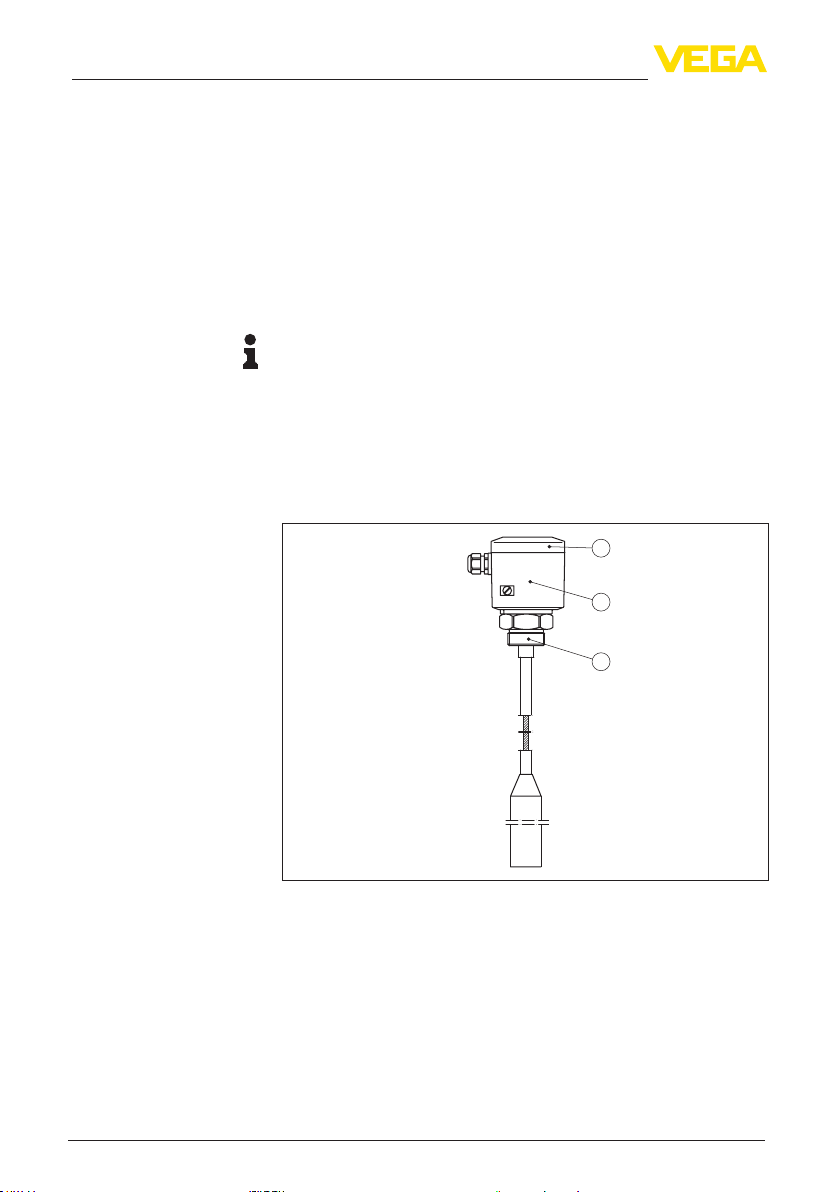
3.1 Conguration.................................................................................................................... 6
3.2 Principle of operation........................................................................................................ 7
3.3 Adjustment ....................................................................................................................... 7
3.4 Packaging, transport and storage..................................................................................... 8
4 Mounting................................................................................................................................... 9
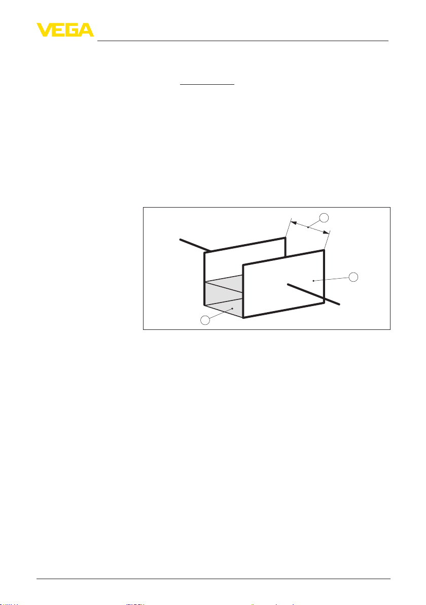
4.1 General instructions ......................................................................................................... 9
4.2 Mounting instructions ..................................................................................................... 10
5 Connecting to power supply................................................................................................. 14
5.1 Preparing the connection ............................................................................................... 14
5.2 Wiring plan - single chamber housing ............................................................................ 14
6 Setup ....................................................................................................................................... 16
6.1 General information........................................................................................................ 16
6.2 Adjustment elements...................................................................................................... 16
6.3 Function table................................................................................................................. 18
7 Diagnostics and servicing .................................................................................................... 20
7.1 Maintenance .................................................................................................................. 20
7.2 Rectify faults................................................................................................................... 20
7.3 Exchanging the electronics module................................................................................ 23
7.4 Shortening of the probe.................................................................................................. 24
7.5 How to proceed if a repair is necessary.......................................................................... 26
8 Dismount................................................................................................................................. 27
8.1 Dismounting steps.......................................................................................................... 27
8.2 Disposal ......................................................................................................................... 27
9 Supplement ............................................................................................................................ 28
9.1 Technical data ................................................................................................................ 28
9.2 Dimensions .................................................................................................................... 32
9.3 Industrial property rights................................................................................................. 33
9.4 Trademark ...................................................................................................................... 33
Editing status: 2023-04-26

3
1 About this document
VEGACAP 35 • Relay (DPDT)
33759-EN-230510
1 About this document
1.1 Function
This instruction provides all the information you need for mounting,
connection and setup as well as important instructions for mainte-
nance,faultrectication,theexchangeofpartsandthesafetyofthe
user. Please read this information before putting the instrument into
operation and keep this manual accessible in the immediate vicinity
of the device.
1.2 Target group
This operating instructions manual is directed to trained personnel.
Thecontentsofthismanualmustbemadeavailabletothequalied
personnel and implemented.
1.3 Symbols used
Document ID
This symbol on the front page of this instruction refers to the Docu-
ment ID. By entering the Document ID on www.vega.com you will
reach the document download.
Information, note, tip: This symbol indicates helpful additional infor-
mation and tips for successful work.
Note: This symbol indicates notes to prevent failures, malfunctions,
damage to devices or plants.
Caution: Non-observance of the information marked with this symbol
may result in personal injury.
Warning: Non-observance of the information marked with this symbol
may result in serious or fatal personal injury.
Danger: Non-observance of the information marked with this symbol
results in serious or fatal personal injury.
Ex applications
This symbol indicates special instructions for Ex applications.
• List
The dot set in front indicates a list with no implied sequence.
1 Sequence of actions
Numbers set in front indicate successive steps in a procedure.
Disposal
This symbol indicates special instructions for disposal.

4
2 For your safety
VEGACAP 35 • Relay (DPDT)
33759-EN-230510
2 For your safety
2.1 Authorised personnel
All operations described in this documentation must be carried out
onlybytrained,qualiedpersonnelauthorisedbytheplantoperator.
During work on and with the device, the required personal protective
equipment must always be worn.
2.2 Appropriate use
The VEGACAP 35 is a sensor for point level detection.
Youcannddetailedinformationabouttheareaofapplicationin
chapter " Product description".
Operational reliability is ensured only if the instrument is properly
usedaccordingtothespecicationsintheoperatinginstructions
manual as well as possible supplementary instructions.
For safety and warranty reasons, any invasive work on the device
beyond that described in the operating instructions manual may be
carried out only by personnel authorised by the manufacturer. Arbi-
traryconversionsormodicationsareexplicitlyforbidden.
2.3 Warning about incorrect use
Inappropriate or incorrect use of this product can give rise to applica-
tion-specichazards,e.g.vesseloverllthroughincorrectmounting
or adjustment. Damage to property and persons or environmental
contamination can result. Also, the protective characteristics of the
instrument can be impaired.
2.4 General safety instructions
This is a state-of-the-art instrument complying with all prevailing
regulations and directives.The instrument must only be operated in a
technicallyawlessandreliablecondition.Theoperatorisresponsi-
ble for the trouble-free operation of the instrument.When measuring
aggressive or corrosive media that can cause a dangerous situation
if the instrument malfunctions, the operator has to implement suitable
measures to make sure the instrument is functioning properly.
The safety instructions in this operating instructions manual, the na-
tional installation standards as well as the valid safety regulations and
accident prevention rules must be observed by the user.
For safety and warranty reasons, any invasive work on the device
beyond that described in the operating instructions manual may be
carried out only by personnel authorised by the manufacturer. Arbi-
traryconversionsormodicationsareexplicitlyforbidden.Forsafety
reasons,onlytheaccessoryspeciedbythemanufacturermustbe
used.
To avoid any danger, the safety approval markings and safety tips on
the device must also be observed.

5
2 For your safety
VEGACAP 35 • Relay (DPDT)
33759-EN-230510
2.5 Conformity
The device complies with the legal requirements of the applicable
country-specicdirectivesortechnicalregulations.Weconrmcon-
formity with the corresponding labelling.
The corresponding conformity declarations can be found on our
homepage.
2.6 Installation and operation in the USA and
Canada
This information is only valid for USA and Canada. Hence the follow-
ing text is only available in the English language.
Installations in the US shall comply with the relevant requirements of
the National Electrical Code (NEC - NFPA 70) (USA).
Installations in Canada shall comply with the relevant requirements of
the Canadian Electrical Code (CEC Par I) (Canada).
2.7 Safety instructions for Ex areas
For applications in explosion-proof areas (Ex), only devices with cor-
respondingExapprovalmaybeused.ObservetheEx-specicsafety
instructions.These are an integral part of the operating instructions
and are enclosed with every device with Ex approval.
2.8 Environmental instructions
Protection of the environment is one of our most important duties.
That is why we have introduced an environment management system
with the goal of continuously improving company environmental pro-
tection.Theenvironmentmanagementsystemiscertiedaccording
to DIN EN ISO 14001.
Pleasehelpusfullthisobligationbyobservingtheenvironmental
instructions in this manual:
• Chapter " Packaging, transport and storage"
• Chapter " Disposal"

6
3 Product description
VEGACAP 35 • Relay (DPDT)
33759-EN-230510
3 Product description
3.1 Conguration
The scope of delivery encompasses:
• VEGACAP 35 point level switch
The further scope of delivery encompasses:
• Documentation
– Operating instructions VEGACAP 35
– Ifnecessary,furthercerticates
Information:
Optional instrument features are also described in this operating
instructions manual.The respective scope of delivery results from the
orderspecication.
The VEGACAP 35 consists of the components:
• Processttingwithprobe
• Housing with electronics
• Housing lid
1
2
3
Fig. 1: VEGACAP 35
1 Housing lid
2 Housing with electronics
3 Processtting
4 Gravity weight
Thetypelabelcontainsthemostimportantdataforidenticationand
use of the instrument:
• Article number
• Serial number
• Technical data
Scope of delivery
Constituent parts
Type label

7
3 Product description
VEGACAP 35 • Relay (DPDT)
33759-EN-230510
• Article numbers, documentation
With the serial number, you can access the delivery data of the instru-
ment via " www.vega.com", " Search".Youcanndtheserialnumber
on the inside of the instrument as well as on the type label on the
outside.
3.2 Principle of operation
VEGACAP 35 is an adjustment-free, capacitive point level sensor for
bulk solids.
Typicalapplicationsareoverllanddryrunprotection.
The probe works in liquids from a dielectric constant of 1.5.
Probe, measured product and vessel wall form an electrical capacitor.
Thecapacitanceisinuencedbythreemainfactors.
1
2
3
Fig. 2: Functional principle - Plate capacitor
1 Distance between the electrode surfaces
2 Size of the electrode surfaces
3 Type of dielectric between the electrodes
The probe and the vessel wall are the capacitor plates.The measured
product is the dielectric. Due to the higher dielectric constant of the
product compared to air, the capacitance increases as the probe is
gradually covered.
The capacitance change is converted by the electronics module into
a switching command.
VEGACAP 35 is a compact instrument, i.e. it can be operated without
external evaluation system. The integrated electronics evaluates the
level signal and outputs a switching signal. With this switching signal,
a connected device can be operated directly (e.g. a warning system,
a pump etc.).
Thedataforpowersupplyarespeciedinchapter"Technical data".
3.3 Adjustment
The probe can be adapted to the dielectric constant of the product
directly on the electronics module.
Application area
Functional principle
Voltage supply

8
3 Product description
VEGACAP 35 • Relay (DPDT)
33759-EN-230510
A switching command can be triggered when the probe is covered or
laid bare.
Ontheelectronicsmoduleyouwillndthefollowingdisplayand
adjustment elements:
• Control lamp for indication of the switching status
• Potentiometer for switching point adaptation (covered)
• DIL switch for mode adjustment
3.4 Packaging, transport and storage
Your instrument was protected by packaging during transport. Its
capacity to handle normal loads during transport is assured by a test
based on ISO 4180.
The packaging of standard instruments consists of environment-
friendly, recyclable cardboard. For special versions, PE foam or PE
foil is also used. Dispose of the packaging material via specialised
recycling companies.
Transport must be carried out in due consideration of the notes on the
transport packaging. Nonobservance of these instructions can cause
damage to the device.
The delivery must be checked for completeness and possible transit
damage immediately at receipt. Ascertained transit damage or con-
cealed defects must be appropriately dealt with.
Up to the time of installation, the packages must be left closed and
stored according to the orientation and storage markings on the
outside.
Unless otherwise indicated, the packages must be stored only under
the following conditions:
• Not in the open
• Dry and dust free
• Not exposed to corrosive media
• Protected against solar radiation
• Avoiding mechanical shock and vibration
• Storage and transport temperature see chapter " Supplement -
Technical data - Ambient conditions"
• Relative moisture 20 … 85 %
With instrument weights of more than 18 kg (39.68 lbs) suitable and
approved equipment must be used for lifting and carrying.
Packaging
Transport
Transport inspection
Storage
Storage and transport
temperature
Lifting and carrying

9
4 Mounting
VEGACAP 35 • Relay (DPDT)
33759-EN-230510
4 Mounting
4.1 General instructions
Note:
For safety reasons, the instrument must only be operated within the
permissibleprocessconditions.Youcannddetailedinformationon
the process conditions in chapter " Technical data" of the operating
instructions or on the type label.
Hence make sure before mounting that all parts of the instrument ex-
posed to the process are suitable for the existing process conditions.
These are mainly:
• Active measuring component
• Processtting
• Process seal
Process conditions in particular are:
• Process pressure
• Process temperature
• Chemical properties of the medium
• Abrasionandmechanicalinuences
The instrument is suitable for standard and extended ambient condi-
tions acc. to DIN/EN/IEC/ANSI/ISA/UL/CSA 61010-1. It can be used
indoors as well as outdoors.
In general, VEGACAP 35 must be mounted vertically. The instrument
must be mounted in such a way that the probe is at the height of the
requested switching point.
Before beginning the welding work, remove the electronics module
from the sensor. By doing this, you avoid damage to the electronics
through inductive coupling.
Ground the probe before welding directly on the rod or cable.
With threaded versions, the housing must not be used to screw in the
instrument! Applying tightening forces on the housing can damage its
internal parts.
Use the hexagon for screwing in.
Use the recommended cables (see chapter " Connecting to power
supply") and tighten the cable gland.
You can give your instrument additional protection against moisture
penetration by leading the connection cable downward in front of the
cablegland.Rainandcondensationwatercanthusdraino.This
applies mainly to outdoor mounting as well as installation in areas
where high humidity is expected (e.g. through cleaning processes) or
on cooled or heated vessels.
Process conditions
Suitability for the ambient
conditions
Switching point
Welding work
Handling
Moisture

10
4 Mounting
VEGACAP 35 • Relay (DPDT)
33759-EN-230510
Fig. 3: Measures against moisture ingress
Theprocessttingmustbesealedifthereisgaugeorlowpressure
in the vessel. Before use, check if the sealing material is resistant
against the measured product and the process temperature.
Themax.permissiblepressureisspeciedinchapter"Technical
data" or on the type label of the sensor.
Metric threads
In the case of instrument housings with metric thread, the cable
glands are screwed in at the factory. They are sealed with plastic
plugs as transport protection.
You have to remove these plugs before electrical connection.
NPT thread
In the case of instrument housings with self-sealing NPT threads, it is
not possible to have the cable entries screwed in at the factory. The
free openings for the cable glands are therefore covered with red dust
protection caps as transport protection.
Prior to setup you have to replace these protective caps with ap-
proved cable glands or close the openings with suitable blind plugs.
4.2 Mounting instructions
Duetotheeectsofagitators,equipmentvibrationorsimilar,thelevel
switch can be subjected to strong lateral forces. For this reason, do
not use an overly long electrode for VEGACAP 35, but check if you
canmountashortlevelswitchonthesideofthevesselinhorizontal
position.
Iftheinstrumentismountedinthellingstream,unwantedfalse
measurement signals can be generated. For this reason, mount the
instrument at a position in the vessel where no disturbances, e.g. from
llingopenings,agitators,etc.,canoccur.
This applies particularly to instrument versions with a longer probe.
Pressure/Vacuum
Cable entries - NPT
thread
Cable glands
Agitatorsanduidization
Inowingmedium

11
4 Mounting
VEGACAP 35 • Relay (DPDT)
33759-EN-230510
Fig.4:Inowingmedium
The probe should protrude into the vessel to avoid buildup. For that
reason,avoidusingmountingbossesforangesandscrewedttings.
This applies particularly to use with adhesive products.
In silos with bulk solids, material cones can form which change the
switching point. Please keep this in mind when installing the sensor
in the vessel.We recommend selecting an installation location where
the probe detects the average value of the material cone.
The probe must be mounted in a way that takes the arrangement of
thellingandemptyingaperturesintoaccount.
To compensate measurement errors caused by the material cone in
cylindrical vessels, the sensor must be mounted at a distance of d/6
from the vessel wall.
Nozzle
Material cone

12
4 Mounting
VEGACAP 35 • Relay (DPDT)
33759-EN-230510
dd
d
6
d
6
Fig. 5: Filling and emptying centred
d
d
6
1
2
3
Fig. 6: Filling in the centre, emptying laterally
1 VEGACAP 35
2 Discharge opening
3 Filling opening

13
4 Mounting
VEGACAP 35 • Relay (DPDT)
33759-EN-230510
Make sure that the max. permissible tensile load of the suspension
cable is not exceeded. The danger of this happening exists particu-
larly with very heavy solids and large meas. lengths.The max. permis-
sible load is stated in chapter " Technical data".
Tensile load

14
5 Connecting to power supply
VEGACAP 35 • Relay (DPDT)
33759-EN-230510
5 Connecting to power supply
5.1 Preparing the connection
Always keep in mind the following safety instructions:
Warning:
Connect only in the complete absence of line voltage.
• The electrical connection must only be carried out by trained,
qualiedpersonnelauthorisedbytheplantoperator.
• Alwaysswitchopowersupply,beforeconnectingordisconnect-
ing the instrument.
Connect the voltage supply according to the following connection
diagrams.The electronics module CAP E31R is designed in protec-
tion class I. To maintain this protection class, it is absolutely neces-
sary that the ground conductor be connected to the internal ground
terminal. Take note of the general installation regulations.
Thedataforpowersupplyarespeciedinchapter"Technical data".
The instrument is connected with standard three-wire cable without
shielding. If electromagnetic interference is expected which is above
the test values of EN 61326 for industrial areas, shielded cable should
be used.
Make sure that the cable used has the required temperature resist-
anceandresafetyformax.occurringambienttemperature
Use cable with round cross-section. A cable outer diameter of
5…9mm(0.2…0.35in)ensuresthesealeectofthecablegland.
Ifyouareusingcablewithadierentdiameterorcross-section,
exchange the seal or use a suitable cable gland.
Note:
When placing the housing cover, make sure that the inspection glass
is above the signal lamp of the electronics module.
5.2 Wiring plan - single chamber housing
We recommend connecting VEGACAP 35 in such a way that the
switching circuit is open when there is a level signal, line break or
failure (safe state).
The relays are always shown in non-operative condition.
The two relays (DPDT) work synchronously. Hence it is possible to
control also e.g. a horn and a magnet valve.
Note safety instructions
Voltage supply
Connection cable
Wiring plan

15
5 Connecting to power supply
VEGACAP 35 • Relay (DPDT)
33759-EN-230510
234567
+
L1
–
N
81
1
2
3
Fig. 7: Wiring plan
1 Relay output
2 Relay output
3 Voltage supply
If inductive loads or stronger currents are switched through, the gold
plating on the relay contact surface will be permanently damaged.
The contact is then no longer suitable for switching low-voltage
circuits.
Inductive loads also result from the connection to a PLC input or
output and/or in combination with long cables. It is imperative that you
take measures to extinguish sparks to protect the relay contact (e.g. Z
diode) or use an electronic version with transistor output.
Connection to a PLC

16
6 Setup
VEGACAP 35 • Relay (DPDT)
33759-EN-230510
6 Setup
6.1 General information
Theguresinbracketsrefertothefollowingillustrations.
Ontheelectronicsmoduleyouwillndthefollowingdisplayand
adjustment elements:
• Potentiometer for switching point adaptation
• DIL switch for mode adjustment - A/B
• Control lamp
Note:
As a rule, always set the mode with the mode switch (5) before start-
ing setup VEGACAP 35. The switching output will change if you set
the mode switch (5) afterwards.This could possibly trigger other con-
nected instruments or devices.
6.2 Adjustment elements
3
4
5
6
1
2
Fig. 8: Electronics module with relay output
1 Type label
2 Connection terminals
3 Tensile proving ring
4 Control lamp
5 DIL switch for mode adjustment
6 Potentiometer for switching point adaptation
The switching status of the electronics can be checked with closed
housing (only plastic housing), see " Function table".
Note:
When placing the housing cover, make sure that the inspection glass
is above the signal lamp (LED) of the electronics module.
Function/Conguration

17
6 Setup
VEGACAP 35 • Relay (DPDT)
33759-EN-230510
ToadjustVEGACAP35,loosenrstofallthefourscrewsontheup-
per side of the instrument with a screwdriver and remove the housing
cover.
You can adapt the switching point to the solid with the potentiometer.
The electronics is adjustment free and an adaption is only necessry in
exceptions. See " Exceptions".
With the mode switch you can change the switching condition of the
relay.Youcansettherequiredmode(A-max.detectionoroverll
protection, B - min. detection or dry run protection).
We recommend connecting according to the idle current principle
(relaycontactdeenergizeswhentheswitchingpointisreached),
because the relay always takes on the same (safe) state if a failure is
detected or in case of mains failure.
Control lamp for indication of the switching status.
• Control lamp on = Relay deenergised
The measuring system is immediately ready for operation.
The switching point must no longer be set with VEGACAP 35.
The probe has an active length and a screen segment.Thanks to the
screen segment, the so called standing capacitance, caused by the
vessel after installation of the probe, is mainly compensated.
As a default setting, the electronics module is adjusted to the basic
capacitance of the probe.The relay output switches when the cover-
ing is in the range of the active probe tip (gravity weight).
Changing dielectric values of the products, such as e.g. caused in
mixing vessels are no problem for the switching accuracy within the
active pin (active pin: 200 mm/7.9 in).The selection of the electrode
length is hence very important because the length of the electrode
determines the switching point.This switching point cannot be shifted
on the electrode. Except: when the electrode cable is shortened.
In exceptions, e.g. in pipelines or if the probe is mounted very close to
thevesselwall,itcanhappenaththeprobesignalsalreadyoverlling
(covering) in uncovered condition.
In this case, the switching point must be re-adjusted.
Foradjustment,thevesselmustnotbelledandtheswitchingpoint
adjustment is also possible in dismounted condition.
A fresh adjustment is necessary in the following cases:
• in narrow space installation conditions with high standing capaci-
tance (e.g. in tubes etc.)
• after exchange of the electronics module
Proceed as follows for a fresh adjustment:
1. Make sure that the probe is uncovered.
2. Pierce the cover of the potentiometer (6) with a screwdriver.
Switching point adapta-
tion (6)
Mode adjustment (5)
Signal lamp (4)
Switching point adjust-
ment
Exceptions
Fresh adjustment

18
6 Setup
VEGACAP 35 • Relay (DPDT)
33759-EN-230510
3. Turnthebelowpotentiometer(6)rstofallanticlockwise(max.20
turns) until the control lamp signals "covered".
ModeA(overllprotection)=controllamplights
Mode B (dry run protection) = control lamp extinguishes
If this condition is already reached, you can continue with the next
step.
4. Turn the potentiometer (6) very slowly (due to the damping) clock-
wise until the control lamp signals "uncovered".
ModeA(overllprotection)=controllampextinguishes
Mode B (dry run protection) = control lamp lights
5. Turn the potentiometer (6) clockwise according to the following
table.
6. The probe is now ready for operation.
Sensitivity
Standard very sensitive
additional turns Dielectric constant >1.5
= 2.5 turns
-
Tab. 1: Number of additional turns for the potentiometer (6)
Note:
With the measurement of products with very low dielectric values, the
number of turns can be reduced up to 1 according to the table.
This setting is too sensitive with conductive, adhesive products.
Note:
When placing the housing cover, make sure that the inspection glass
is above the signal lamp of the electronics module.
6.3 Function table
The following table provides an overview of the switching conditions
depending on the set mode and the level.
Level Switching status Control lamp
Mode A
Overowprotec-
tion 53 4
(8)(6) (7)
Relayenergized
Mode A
Overowprotec-
tion 53 4
(8)(6) (7)
Relay deener-
gized

19
6 Setup
VEGACAP 35 • Relay (DPDT)
33759-EN-230510
Level Switching status Control lamp
Mode B
Dry run protection 53 4
(8)(6) (7)
Relayenergized
Mode B
Dry run protection 53 4
(8)(6) (7)
Relay deener-
gized
Failure of the sup-
ply voltage
(mode A/B)
any
53 4
(8)(6) (7)
Relay deener-
gized

20
7 Diagnostics and servicing
VEGACAP 35 • Relay (DPDT)
33759-EN-230510
7 Diagnostics and servicing
7.1 Maintenance
If the device is used properly, no special maintenance is required in
normal operation.
The cleaning helps that the type label and markings on the instrument
are visible.
Take note of the following:
• Use only cleaning agents which do not corrode the housings, type
label and seals
• Use only cleaning methods corresponding to the housing protec-
tion rating
7.2 Rectify faults
The operator of the system is responsible for taking suitable meas-
ures to rectify faults.
Thedeviceoersmaximumreliability.Nevertheless,faultscanoccur
during operation.These may be caused by the following, e.g.:
• Sensor
• Process
• Voltage supply
• Signal processing
Therstmeasuretotakeistochecktheoutputsignal.Inmanycases,
thecausescanbedeterminedthiswayandthefaultsquicklyrectied.
Depending on the reason for the fault and the measures taken, the
steps described in chapter " Setup" must be carried out again or must
be checked for plausibility and completeness.
Should these measures not be successful, please call in urgent cases
the VEGA service hotline under the phone no. +49 1805 858550.
The hotline is also available outside normal working hours, seven
days a week around the clock.
Sinceweoerthisserviceworldwide,thesupportisprovidedin
English.The service itself is free of charge, the only costs involved are
the normal call charges.
Maintenance
Cleaning
Reaction when malfunc-
tion occurs
Causes of malfunction
Faultrectication
Reaction after fault recti-
cation
24 hour service hotline
Table of contents
Other Vega Measuring Instrument manuals

Vega
Vega VEGAPULS 61 User manual

Vega
Vega VEGAFLEX 86 User manual

Vega
Vega VEGACAP 66 User manual

Vega
Vega VEGABAR 83 User manual

Vega
Vega VEGAFLEX 81 User manual

Vega
Vega VEGAPULS 63 User manual

Vega
Vega VEGABOX 03 User manual

Vega
Vega VEGAVIB 61 User manual

Vega
Vega VEGAPULS 61 User manual

Vega
Vega VEGAMIP T61 User manual

Vega
Vega VEGAPULS 56K User manual

Vega
Vega VEGAPULS 31 User manual

Vega
Vega VEGABAR 66 User manual

Vega
Vega VEGAPULS WL 61 User manual

Vega
Vega VEGAPULS 61 User guide

Vega
Vega VEGABAR 17 User manual

Vega
Vega VEGAWAVE 63 User manual

Vega
Vega FiberFlex LFXG-H User manual

Vega
Vega INFO-1 User manual

Vega
Vega VEGAPULS SR 68 User manual