GASTRON GTD-6000 User manual

GTD-6000
Instruction Manual
Read in detail for correct use.

Gas & Flame
Detection System
GTD-6000
Instruction Manual
When abnormalities occur after purchasing the product,
please contact the following address.
·Address : 23 Gunpo Advanced Industry 1-ro,
Gunpo-si, Gyeonggi-do
·Tel : 031-490-0800
·Fax : 031-490-0801
·URL : www.gastron.com
·e-mail : [email protected]

www.gastron.com
02_03
Greetings
We sincerely thank you for purchasing the product of Gastron Co. Ltd.
Our Gastron Co.Ltd. is a company specialized in Gas detector and Gas Monitoring System, being
recognized by many consumers due to the best quality and use convenience. We always enable you
consumers to find desired products nearby and are ceaselessly studying and striving for development
of Gas detectors satisfying customers. From now on, solve all anguishes concerning Gas detector with
the products of Gastron Co. Ltd, We Gastron Co. will take a responsibility and give you satisfaction.
In the present instruction manual, operation method for Gas detector as well as simple methods for
maintenance and repair, etc. are recorded If you read it in detail and keep it well, for reference when
you have questions, then it will give you much help.
The present product and the product manual can be changed without advance notice for performance improvement and
use convenience of the product.
■ For accurate operation of Gas detector, check up and calibrate for more than once in every 6 months.
( * See No. 13 of KOSHA GUIDE : P-135-2013 / 8.3 paragraph on qualification and calibration)
■ For accurate operation of Gas detector, checkup and calibration with calibration gas before measurement
is recommended.
■
When not calibrated, it may cause malfunction of the equipment due to problems resulting from Sensor aging.
■ When the present instrument should be dismantled, those with professional skills for Gas detector should
conduct the operation.
■ For power supply cable, wire specifications should be determined by referring to the item of "Length of
installed cable".
■ For the contents on checkup and calibration of Gas detector, please use our company's engineering
department , e-mail, or web site.
* KOSHA GUIDE : P-135/6-2018
Calibration should be executed at the periods required by the manufacturer, and should be executed
every quarter unless there are separate calibration periods.

Contents
GTD-6000
Instruction Manual
1. Overview ··························································································· 6
2. Configuration ························································································ 6
3. Specification ······················································································· 7
3.1. Basic Specifications ··········································································· 7
3.2. Mechanical Specifications ····································································· 7
3.3. Electrical Specifications (Standard Type) ························································ 8
3.4. Environmental Specifications ··································································· 9
4. Name and Description of Each Part ································································ 10
4.1. Components ················································································· 10
5. Installation ························································································· 13
5.1. Detachment of Terminal Block Cover ··························································· 13
5.2. Power Terminal Configuration ·································································· 13
5.3. Signal Terminal Configuration ·································································· 15
5.4. Relay Terminal Configuration ··································································· 16
5.5. Installation Cable Length ······································································· 18
6. Detector Operation Flow ··········································································· 19
6.1. Initial Operation Status (Power On) ······························································ 19
6.2. Measuring Mode ·············································································· 19
6.3. Gas Test Function Operation ··································································· 20
6.4. Set-up Mode Entry Status ····································································· 20
6.5. Operation Flow ··············································································· 20
6.6. Menu Configuration Table ····································································· 21
7. System Mode ······················································································ 23
7.1. PROGRAM MODE ············································································· 23
7.2. CALIBRATION MODE ·········································································· 25

www.gastron.com
04_05
Contents
7.2.1. Zero Calibration ······································································· 25
7.2.2. Span Calibration ······································································ 26
7.3. ALARM MODE ················································································ 27
8. Troubleshooting ··················································································· 30
8.1. Fault List ····················································································· 30
8.2. Recovery List ················································································ 30
9. Interface Configuration ············································································ 31
9.1. MODBUS RS485 ·············································································· 31
9.1.1. Interface setting ········································································ 31
9.1.2. MODBUS RS485 Register map ·························································· 31
10. Drawings and Dimensions ········································································· 32
10.1. Drawing 1 ···················································································· 32
10.2. Drawing 2 ···················································································· 33
11. Precautions before Installation ····································································· 34
11.1. Selecting a Place for Installation (Occupation Safety and Health Act Data) ·························· 34
11.2. Selecting a Site for Installation (High-Pressure Gas Safety Control Act Data) ························ 34
11.3. Precautions during Installation ································································· 34
12. Revision History ··················································································· 35

GTD-6000 gas detector has been developed to detect gas leaked from industrial sites and various toxic gases
generated from factories, gas storages, and manufacturing processes that produce or use toxic gases and to prevent
accidents in advance. GTD-6000 gas detector is installed in areas with gas leak hazards and continuously monitors
gas leak. It displays measurements on built-in FND within the gas detector, output DC 4~20 mA standard signal and
RS-485 network signal, and provides relay contact signal in case of gas leak alarm event.
Also, DC 4~20 mA standard output is capable of connecting max. 2,500 m for output signal transmission between
gas detector and receiver (when using VVS or CVVSB 1.5sq↑ Shield Cable). For RS-485 network signal, it is
capable of transmitting up to 1,000 m (when using RS-485 designated shield cable).
GTD-6000 case is made of ABS for protection.
This product can be installed in areas with combustible gas leak and explosion hazards. 4-Digit FND built-in the gas
detector displays gas leak status as installed site. Internal structure consists of display that indicates measurement,
main control that measures and controls gas concentration and flow rate, and terminal that sends current output (DC 4
~ 20 mA) or RS-485 network signal, and alarm signal externally.
2. Conguration
1. Overview
GTD-6000
Instruction Manual
[Figure 1. GTD-6000 Overview]
Gas
Sensor Module
Main Board
(Transmitter)
+24V DC
4-20mA Analog
Signal Output
Display Board
(User Interface)
Transmitter enclosure
Safety Power Supply Unit
(24VDC)
Safety Controller
(PLC or DCS)
GTD-6000Ex Gas Detector
Hazardous Area (Filed) Safe Area
Warning Light

www.gastron.com
06_07
3. Specication
3.1. Basic Specifications
ITEMS SPECIFICATION
Measuring Type Diffusion
Measuring Value Display 4-digit 1.8" FND Display
Measuring Method Catalytic
Electro-Chemical Cell
Detectible Gas
Combustible Gas
Toxic Gas)
Oxygen (Note 1)
Measuring Range Capable to display 0000 ~ 9999 (Note 1)
Accuracy ≤ ±3% / Full Range
Zero Drift ≤ 2% / Full Range
Response Time Depends on Sensor Module.
Refer to Sensor Specification or Contact in case for Special Gas.
Alarm Indicator Visible Indicator: 3-Alarm, Trouble LED, Warning Light
Approvals Classification Audible Indicator: Buzzer Signal (85 dB)
-
Basic Interface Analog 4-20mA current interface
Option MODBUS RS485
Warranty
Transmitter 2Year
Sensor 1Year
3.2. Mechanical Specifications
ITEMS SPECIFICATION
Dimension) 235.6(W) × 355.5(H) × 109.3(D) mm
Weight including Sensor App. 1.75kg
Mounting type Wall mount
Cable inlet 3/4" PF ( 1/2" or 3/4" NPT )
Body material
Transmitter
ABS
Sensor
PVC
Warning Light
Poly Carbonate
※ Note1. Refer to the measured gas list for measured gases and their ranges. Contact us for special gas.

3.3. Electrical Specifications (Standard Type)
ITEMS SPECIFICATION
Input Voltage(AC Type/Standard)
Absolute min:
Nominal:
Absolute max:
AC 90V
AC 220V
AC 250V
Input Voltage(DC Type)
※ Customer supplied PSU must meet requirements
IEC1010-1 and CE Marking requirements.
Absolute min:
Nominal:
Absolute max:
Ripple maximum allowed:
18V
24V
31V
1V pk-pk
Wattage(DC Type) Max. wattage:
Max. current:
6.72W @+24 VDC
280mA @+24 VDC
Analog output Current
0-20mA(500 ohms max load)
All readings ± 0.2mA
Measured-value signal:
4mA(Zero) to 20mA(Full Scale)
Fault:
0-100% LEL:
100-109%LEL:
Over 110% LEL:
Maintenance:
0mA
4mA - 20mA
20mA - 21.4mA
21.6mA
3mA
Analog output current ripple & noise max ±20uA
Relay contact Alarm1, Alarm2, Alarm3, Fault Relay
Rated 1.0 A @ 30VDC or 0.5 A @ 125 VAC
Wiring requirement
Power CVVS or CVVSB with shield
Analog CVVS or CVVSB with shield
RS485 STP(Shielded Twisted Pair)
Cable Connection Length Analog 2500m
RS485 1000m
EMC Protection: Complies with EN50270
3. Specication
GTD-6000
Instruction Manual

www.gastron.com
08_09
3. Specication
3.4. Environmental Specifications
ITEMS SPECIFICATION
Operation Temperature Transmitter -20 to 60 ℃
Sensor Refer to Sensor Specification
Storage Temperature Transmitter -20 to 60 ℃
Sensor Refer to Sensor Specification
Operation Humidity Transmitter 5 to 99% RH (Non-condensing)
Sensor Refer to Sensor Specification
Pressure Range 90 to 110KPa
Max. air velocity 6m/s

4. Name and Description of Each Part
GTD-6000
Instruction Manual
4.1. Components
[Figure 2. GTD-6000 Components]

www.gastron.com
10_11
4. Name and Description of Each Part
NO NAME DESCRIPTIONS
1Case cover
It is made of ABS Material. It fixes the display and protects the circuit from surrounding environment
and external shock.
2Case body It is made of ABS Material. It fixes the Main PCB and protects the circuit from surrounding
environment and external shock.
3Warning Light Lights on upon an event of alarm.
4Mount Boss It is a bracket hole to fix the product on wall or other mount hole. It consists of 2 of Ø4.4 hole.
5Conduit connection 1 hole of Ø16.5 and 5 holes of Ø 20.5 are set at the bottom part.
Depending on site condition, power and signal cables, etc. are connected by cable inlet.
6O-Ring It works as waterproofing material to prevent rainwater from entering inside. It is made of NBR
material.
7Power LED When power is supplied normally, the power LED lights on.
8Stand-by LED When the detector is in stand-by mode, LED flickers.
9Fault LED It lights on in an event of trouble.
10 Alarm 3 LED It lights on in an event of Alarm 3.
11 Alarm 2 LED It lights on in an event of Alarm 2.
12 Alarm 1 LED It lights on in an event of Alarm 1.
13 Function KEY
It is a key to convert or set a mode in function setting mode. When FUNC key is pressed for
2 sec or longer in measuring mode, it enters function setting menu mode.
(Configuration, Program, Calibration, Alarm, etc.)
14 UP KEY It is a key to increase a set value in function setting mode.
15 DOWN KEY (Stand-by)
It is a key to decrease a set value in function setting mode. When down key is pressed for
2 sec longer in measuring mode, it enters test mode (EMS: Emergency Maintenance System).
STD-BY LED flashes.
In stand-by mode, pressing down key for 2 sec or longer releases it.
16 TEST KEY Pressing “TEST” key enters a mode that performs self-test. Measurement FND flickers and
the value can be adjusted using “TEST” key to check the alarm operation status.
17 RESET KEY To change into menu mode or measuring mode from function setting mode, use reset key to
return.
18 Buzzer Stop KEY Used to stop buzzer in an event of alarm.
19 Buzzer Operates in a continuous tone upon an event of warning or fault during a test.
20 FND PCB Ass'y Displays measurement from detector in a continuous manner. During test, it displays user defined
value with flickering.
21 Terminal Block Cover To supply power to the equipment, open the terminal block cover and connect power cable.
22 Main PCB Amplifies fine outputs generated from Sensor Element to transmit a converted output in 4~20 mA
DC standard. It sends data to display part.
23 SMPS It is a converter that changes 220 V AC to 24 V DC.
24 Power ON/OFF Switch It is a switch used to turn ON and OFF of the control unit power. When performing cable wiring
work, power must be turned OFF.
25 FUSE It works as a breaker to protect the equipment by disconnecting power when overcurrent flows.

GTD-6000
Instruction Manual
[Table 1. GTD-5000F Component Description]
NO NAME DESCRIPTIONS
26 Power Input Terminal
(CN7) It is a terminal for external power cable connection.
27 Signal output terminal
(CN5)
Used for connecting cables, etc. for Relay Dry Contract Signal Output such as warning,
failure, etc. and Switch Signal Output, etc.
28 Signal I/O terminal (CN6) Used for connecting cables, etc. for power supply of gas sensor, 4~20 mA current output,
and RS-485 MODBUS Network, etc.
29 Cover Fixing Button Device to fix the cover on the case body. To open the cover, push the hook and pull the cover
towards the front.
30 RS-485 module(Option) RS-485 network module is isolated type that connects PC and other external network devices
to receive and transmit the current concentration and settings, etc.
31 Sensor PCB Sensor operation board that is set by combustible and toxic gas sensor.
4. Name and Description of Each Part
www.gastron.com
12_13
5. Installation
■ It is prohibited for an individual, other than an approved user or a technician responsible for installation and
repair from the head office, to install a gas leak sensor on site or open the cover of the installed gas leak sensor
and manipulate it. This may cause serious loss of life and property from fire, explosion, and etc. In addition,
please check whether there is any remaining explosive gas or combustible material in the surroundings. Power
must be turned off before performing work.
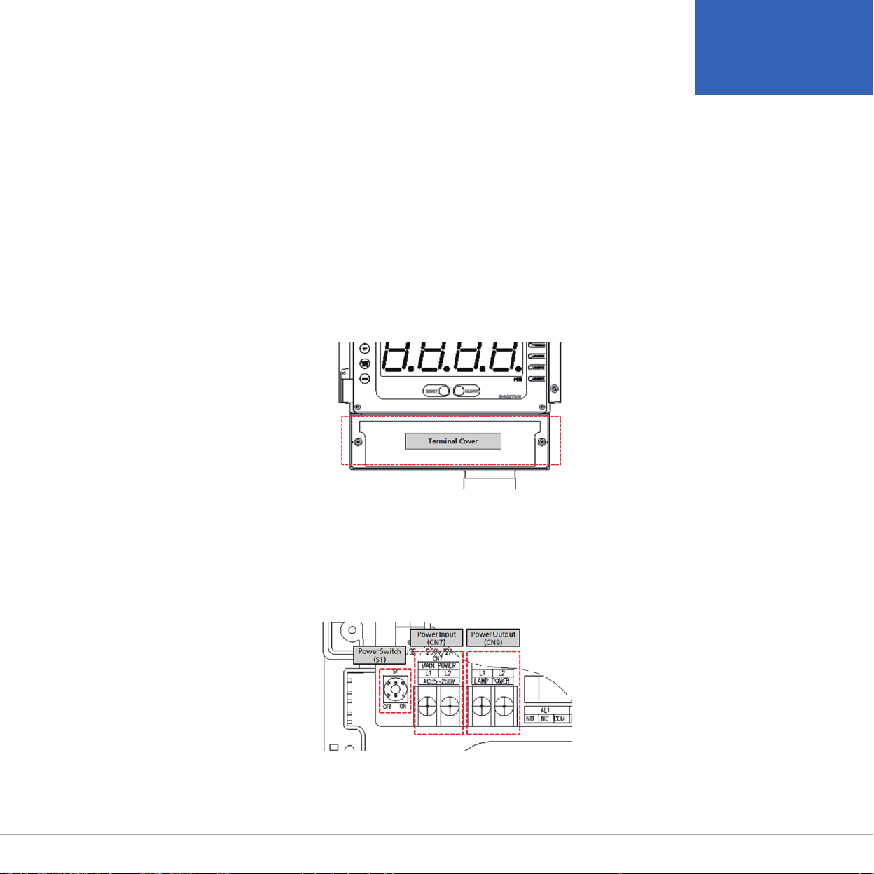
[Figure 3. Terminal Block Cover Configuration]
5.1. Detachment of Terminal Block Cover
■ Loosen the set screws at each side of terminal block cover located front bottom of the product then detach
the cover. Terminal block for power and various signal connection in Terminal PCB appears.
[Figure 4. Power Terminal Configuration]
5.2. Power Terminal Configuration
■
After detaching terminal block cover, configure power using CN7 terminal built on the left side of Terminal PCB.
The configured power is connected using CN9 and is convenient for supplying power to external devices.

GTD-6000
Instruction Manual
■
Connected power can be turned ON/OFF using S1 switch.
■
The product has AC power as a default setting. When it is desired to use DC24V, a separate request must be made
when ordering the product. When the product has been delivered as DC24V Type upon a customer request, (+)
and (-) of DC24V shall be connected to L1 and L2, respectively.
■
Use CVVS or CVVSB 1.5sq↑ Shield Cable for wiring.
Terminal PIN NAME DESCRIPTION
AC MODE DC MODE
CN7 L1 AC220V L1 POWER+(24V)
L2 AC220V L2 POWER-(GROUND)
CN9 L1 AC220V L1 POWER+(24V)
L2 AC220V L2 POWER-(GROUND)
[Table 2. Power Terminal Detailed Description]
5. Installation

www.gastron.com
14_15
[Figure 5. Signal Terminal Configuration]
5.3. Signal Terminal Configuration
■
Using CN6 terminal, connect 4~20 mA output, External Reset, RS485, and gas sensor. Terminal configuration is
as shown in the table below.
■
Note 1) When RS485 Option does not exist, RS485 function does not operate.
[Table 3. Signal Terminal Description]
Function Terminal Name Description
4-20mA
Output
VISO External power input terminal for 4~20 mA Sink Driver
mA Output terminal for 4~20 mA Source Driver
-4-20mA Common Terminal
RESET +External Reset S/W + Terminal. When + and - terminals short, alarm reset function operates.
-External Reset S/W - Terminal
RS485 ARS485 A Terminal (TRXD+ or P)
BRS485 B Terminal (TRXD- or N)
SENSOR
Combustible Sensor Toxic Sensor O2 Sensor (Galvanic Method)
1Red Cable Blue Cable N.C
2White Cable Red Cable Red Cable
3Green Cable White Cable White Cable
4Blue Cable N.C N.C
5. Installation

GTD-6000
Instruction Manual 5. Installation
[Figure 6. Relay Terminal Configuration]
5.4. Relay Terminal Configuration
■
Using CN5 terminal, it consists of 3 SPDT-type Alarm relay and 1 SPDT-type Trouble relay.
LP terminal output DC +24V power regardless of AC, DC power mode. This is to use an external DC flash light or
external devices.
[Figure 7. Relay Output Description]
Function Pin Terminal Name Description
4-20mA
Output
1NO Alarm1 Normal Open
2NC Alarm1 Normal Closed
3COM Alarm1 Common
Alarm2
4NO Alarm2 Normal Open
5NC Alarm2 Normal Closed
6COM Alarm2 Common
Alarm3
7NO Alarm3 Normal Open
8NC Alarm3 Normal Closed
9COM Alarm3 Common
Trouble
10 NO Trouble Normal Open
11 NC Trouble Normal Closed
12 COM Trouble Common
LP 13 +External Power (DC 24 V) + Output
14 -External Power (DC 24 V) - Output

www.gastron.com
16_17
5. Installation
■
When gas concentration is detected to be above the set value for alarm, alarm function counts the dwell time and if it
is above the set dwell time, alarm function operates.
■
Alarm relay turns on when it is above the alarm dwell time. When Alarm Latch Type is at "ON" mode and alarm function
runs, the alarm status and gas concentration value stays at the maximum value. When gas concentration decreases
below the alarm value, alarm does not get released and "RESET" S/W must be ran to release it.
■
When Alarm Latch Type is OFF, Alarm is released automatically in accordance to gas concentration.

GTD-6000
Instruction Manual 5. Installation
5.5. Installation Cable Length
[Figure 8. GTD-6000 Installation Cable Length Calculation]
■ The maximum length between GTD -6000 and power supply is decided by wire specification.
■ Max. Installation Length = VMAXDROP ÷ IMAX ÷ WIRER/m ÷ 2
■
VMAXDROP: Maximum Power Loop Voltage Drop (= Power Supply voltage - min operating voltage)
■ IMAX: Max. Current Value of GTD-6000
■ WIRER/m: The resistance of the wire (ohms/meter value available in wire manufacturer's
specification data sheet),
■ Installation length example using 24 V power supply and 16 AWG is as follows.
■ GTD-6000 minimum operating voltage = 18 Vdc
■ VMAXDROP = 24 - 18 = 6V
■ IMAX = 0.28A( 280mA )
■ 6 ÷ 0.28 ÷ 0.01318 ÷ 2 = 812.92m ≒ 812m
[Table 4. GTD-6000 Power Cable Installation Length]
AWG mm
2
COPPER RESISTANCE(ohms/m) METERS
12 3.31 0.00521 2056
14 2.08 0.00828
1293
16
1.31 0.01318 812
18 0.82 0.02095
511
20 0.518 0.0333
321
■ Power cable installation for each cable type is as shown in the table below.

www.gastron.com
18_19
6. Detector Operation Flow
6.1. Initial Operation Status (Power On)
■
After wiring to power terminal at the top of Terminal PCB board then supply power, the following contents are
displayed on LCD. Approx. 30 min of stabilization of time is needed from the initial supply of operation power and it
starts to operate normally after sufficient stabilization.
- After GTC-6000 power turns ON, the current F/W version is displayed.
- After warming-up by "SELF" flashing for approx. 30 sec on FND of concentration display, it immediately
enters the measurement mode.
- If there is a trouble with the equipment at this time, fault alarm occurs.
6.2. Measuring Mode
■
After power on, when there is no error from "SELF TEST", it automatically enters Measuring Mode.
- Displays gas concentration received by the detector on FND digital display in numbers.
- When the sensor is not connected, there is a problem with the sensor, or sensor PCB is not combined,
"FALt" message flickers in 0.5 sec interval on the display.
- When the input value from the sensor is under 10% below the set high scale value, "Undr" displays and
flashes at 0.5 sec interval.
- Trouble LED lights on, warning light flashes, and buzzer sounds.
- When "BZSTOP" KEY is pressed, warning light turns on and the buzzer stops.
- When the input current from the sensor is over 10% above the set high scale value, "oUEr" displays and
flashes at 0.5 sec interval.
- Alarm 1, 2, 3 LED lights flickers, warning light flickers, and buzzer sounds.

GTD-6000
Instruction Manual 6. Detector Operation Flow
6.3. Gas Test Function Operation
■
Pressing "TEST" key for 2 sec or longer in gas concentration display mode enters Test mode. In test mode, when
it passes 30 min after the last KEY control, it automatically returns to the gas concentration display mode.
- When it enters Test mode, gas concentration number displays and flickers.
- This function enables testing at channel unit without injecting gas to the detector sensor. It can set
an arbitrary concentration when the user presses "Test" key and alarm function operates normally with
a user-defined concentration.
- When "FUNC" key is pressed 2 sec or longer, it enters FND / LED Test function.
- When "RESET" key is pressed, it returns to gas concentration display mode
▼ ▲
120% of
Full Range
6.4. Set-up Mode Entry Status
- Pressing "TEST" key for 2 sec or longer in gas concentration display mode enters Test mode.
- In program setting mode, when it passes 10 sec after the last Key control, it automatically returns to
gas concentration display mode.
- It requires password. Factory setting is "00".
- "00" means that the password is not entered.
- After entering password, by pressing FUNC SW, each mode can be set.
- By using "UP" or "DOWN" KEY, the user can confirm in an order of Program -> Calibration -> Alarm
-> Sensor -> Option -> Version -> Test mode.
▼ ▲
6.5. Operation Flow
■
After power on, it passes self-diagnostic process then enters Measuring Mode. Here, by operating front keys, you
can go to internal System Mode.
■
Timeout (time after the last key control) for Level1 and Level2 are 10 sec. It is set to 1 h for Level2 Calibration and Test Mode.
■
When "RESET" key contacts at Program Mode Screen, it returns to Measuring Mode. When "RESET" key contacts
at each Program Setting Screen, it returns to the parent step.
[Table 5. Operation Key Description]
ITEM NAME DESCRIPTION
FUNC Function key Detector Mode Setting Entry Function (Enter Push key for 2 sec or longer in measuring mode)
Level2 next stage entry function and setting value saving function
RESET Reset key Move to the previous stage from the level entered.
↑Up key Next level mode that is configured in LEVEL1 and Change in Level2 setting Plus
↓Down key Next level mode that is configured in LEVEL1 and Change in Level2 setting Minus
Table of contents
Other GASTRON Measuring Instrument manuals


Popular Measuring Instrument manuals by other brands


Emerson
Emerson Rosemount 3410 Series Maintenance and troubleshooting manual

Maxcess
Maxcess Boschert VT Chuck 30-40 Additional Instructions for Installation and Operation

Triplett Corporation
Triplett Corporation 630 Type 5 instruction manual

MW TOOLS
MW TOOLS OPDMP manual

Logitek
Logitek BRIGHT-VU Operation & service manual

ARNOLD
ARNOLD OPPAMA PET-1000R instruction manual