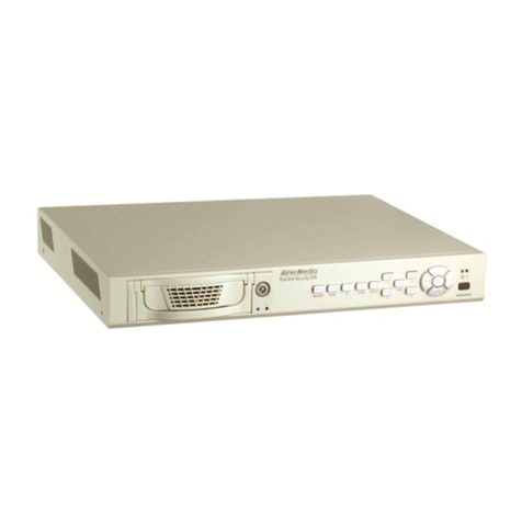
Gatekeeper Systems 504HD User manual

DN2731_504HD_UserGuideManual
1
Safety, Security, Peace of Mind
504HD USER GUIDE AND MANUAL

2
Table of Contents.
TABLE OF FIGURES. ..........................................................................................................................................................................................................................................5
Introduction...........................................................................................................................................................................................................................................................6
Glossary ..................................................................................................................................................................................................................................................................6
Important Safeguards and Warnings. ....................................................................................................................................................................................................7
Package Checklist..............................................................................................................................................................................................................................................8
Download Kits......................................................................................................................................................................................................................................................9
SD Download Kit............................................................................................................................................................................................................................................9
SD Download Kit Plus A.............................................................................................................................................................................................................................9
SD Download Kit Plus B.............................................................................................................................................................................................................................9
System Overview. ............................................................................................................................................................................................................................................10
Front View......................................................................................................................................................................................................................................................10
Rear View.......................................................................................................................................................................................................................................................11
Accessing Video on 504-HD COMRAD™ (Hard Disk Drive). ....................................................................................................................................................11
Mounting the System....................................................................................................................................................................................................................................12
Installation / Environmental Requirements.................................................................................................................................................................................12
Power Connector (CAB0000307)...................................................................................................................................................................................................12
Sensors...........................................................................................................................................................................................................................................................13
GPS.........................................................................................................................................................................................................................................................................14
Driver Alert Button.........................................................................................................................................................................................................................................14
Using the Remote Control..........................................................................................................................................................................................................................15
Numeric Keypad.........................................................................................................................................................................................................................................15
Setup Menu Navigation: .........................................................................................................................................................................................................................15
System Configuration....................................................................................................................................................................................................................................16
Recorded Video................................................................................................................................................................................................................................................16
REC. SEARCH...............................................................................................................................................................................................................................................16
EVENT FILES. ................................................................................................................................................................................................................................................17
System Settings...............................................................................................................................................................................................................................................18
DATE TIME.....................................................................................................................................................................................................................................................18
GENERAL........................................................................................................................................................................................................................................................19
REGISTER INFO ...........................................................................................................................................................................................................................................19
FORMAT .........................................................................................................................................................................................................................................................20
UPGRADE ......................................................................................................................................................................................................................................................20
USER SECURITY .........................................................................................................................................................................................................................................20
CONFIG............................................................................................................................................................................................................................................................21
SYSTEM LOG................................................................................................................................................................................................................................................21
BLACKBOX FILE..........................................................................................................................................................................................................................................21
GEO FENCING ..............................................................................................................................................................................................................................................21
RECORD...............................................................................................................................................................................................................................................................22

3
OPTIONS 1. ...................................................................................................................................................................................................................................................22
OPTIONS 2. ...................................................................................................................................................................................................................................................23
OSD OVERLAY .............................................................................................................................................................................................................................................23
CAMERA SETTINGS..................................................................................................................................................................................................................................24
RECORD SETTING......................................................................................................................................................................................................................................24
SUB STREAM...............................................................................................................................................................................................................................................24
SCHEDULE.....................................................................................................................................................................................................................................................24
OTHER SETTING .........................................................................................................................................................................................................................................25
NETWORK ..........................................................................................................................................................................................................................................................26
LOCAL..............................................................................................................................................................................................................................................................26
SERVER...........................................................................................................................................................................................................................................................26
WIFI...................................................................................................................................................................................................................................................................28
MOBILE NETWORK...................................................................................................................................................................................................................................28
FTP SETTINGS .............................................................................................................................................................................................................................................28
ROUTE .............................................................................................................................................................................................................................................................28
EVENT ...................................................................................................................................................................................................................................................................29
SENSOR..........................................................................................................................................................................................................................................................29
ALARM OUTPUT ........................................................................................................................................................................................................................................29
SPEED..............................................................................................................................................................................................................................................................30
ACCELERATION...........................................................................................................................................................................................................................................30
TEMPERATURE................................................................................................................................................................................................................................................31
CAMERA.........................................................................................................................................................................................................................................................31
VOLTAGE ........................................................................................................................................................................................................................................................31
EMERGENCY EVENT. ...............................................................................................................................................................................................................................31
PERIPHERAL......................................................................................................................................................................................................................................................32
PTZ....................................................................................................................................................................................................................................................................32
EXT. COM .......................................................................................................................................................................................................................................................32
SMART BATTERY. .....................................................................................................................................................................................................................................32
SYSTEM INFORMATION. .............................................................................................................................................................................................................................33
SYSTEM..........................................................................................................................................................................................................................................................33
DIAL STATUS. ..............................................................................................................................................................................................................................................33
HISTORY.........................................................................................................................................................................................................................................................33
MODULES......................................................................................................................................................................................................................................................34
Overview...............................................................................................................................................................................................................................................................35
INSTALLATION..................................................................................................................................................................................................................................................35
Using G4 Viewer..............................................................................................................................................................................................................................................37
Opening Screen. .........................................................................................................................................................................................................................................37
G4 Calendar Interface.............................................................................................................................................................................................................................39
HDD ..................................................................................................................................................................................................................................................................40

4
Directory.........................................................................................................................................................................................................................................................40
Device. .............................................................................................................................................................................................................................................................40
Time Bar.........................................................................................................................................................................................................................................................41
Calendar or Playback Interface. .........................................................................................................................................................................................................41
Playback Details..........................................................................................................................................................................................................................................41
Playback Controls. .....................................................................................................................................................................................................................................41
System Settings..........................................................................................................................................................................................................................................42
Saving a Clip..................................................................................................................................................................................................................................................42
Exporting a Clip............................................................................................................................................................................................................................................44
Export to an AVI File..................................................................................................................................................................................................................................44
G4 Playback Interface...................................................................................................................................................................................................................................45
Playing Back a Video File. ............................................................................................................................................................................................................................46
Event Playback..................................................................................................................................................................................................................................................46
Sensor / Alarm Playback 1.......................................................................................................................................................................................................................46
Sensor / Alarm Playback 2.......................................................................................................................................................................................................................47
Vehicle Speed Playback................................................................................................................................................................................................................................47
Blurring an Image. .....................................................................................................................................................................................................................................47
APPENDIX...........................................................................................................................................................................................................................................................49
Camera Mounting and Connections. ...............................................................................................................................................................................................49
Camera Installation...................................................................................................................................................................................................................................49
Suggested Camera Locations.............................................................................................................................................................................................................51
Video Alignment Cable: CAB000157 .............................................................................................................................................................................................52
504-HD Quick Install Guide...................................................................................................................................................................................................................53
Quick Configuration Guide. ....................................................................................................................................................................................................................53
Warranty.............................................................................................................................................................................................................................................................55
Contact Information.......................................................................................................................................................................................................................................56

5
TABLE OF FIGURES.
FIGURE 1: 504-HD FRONT VIEW. ..............................................................................................................................10
FIGURE 2: 504-HD REAR VIEW..................................................................................................................................11
FIGURE 3: 504-HD COMRAD™ REAR VIEW ................................................................................................................11
FIGURE 4: SENSOR CONNECTION EXAMPLE...............................................................................................................13
FIGURE 5: SENSOR SETUP. .......................................................................................................................................13
FIGURE 6: REMOTE CONTROL...................................................................................................................................15
FIGURE 7: REC SEARCH. ...........................................................................................................................................16
FIGURE 8: EVENT SEARCH. .......................................................................................................................................17
FIGURE 9: DATE / TIME SETUP. ................................................................................................................................18
FIGURE 10: CONFIG SCREEN.....................................................................................................................................21
FIGURE 11: RECORD SETTINGS. ...............................................................................................................................22
FIGURE 12: CAMERA SETTINGS.................................................................................................................................24
FIGURE 13: LOCAL NETWORK SETTINGS. ..................................................................................................................26
FIGURE 14: WI-FI SETTINGS.....................................................................................................................................28
FIGURE 15: SENSOR SETTINGS/ACTIONS. .................................................................................................................29
FIGURE 16: SPEED....................................................................................................................................................30
FIGURE 17: ACCELERATION. .....................................................................................................................................30
FIGURE 18: EMERGENCY EVENT................................................................................................................................31
FIGURE 19: SYSTEM INFO.........................................................................................................................................33
FIGURE 20: MODULES...............................................................................................................................................34
FIGURE 21: OPENING SCREEN ICONS........................................................................................................................37
FIGURE 22: SEARCH FILTER......................................................................................................................................37
FIGURE 23: G4 CALENDAR INTERFACE. ....................................................................................................................39
FIGURE 24: PLAYBACK CONTROLS. ...........................................................................................................................41
FIGURE 25: SYSTEM SETTINGS. ................................................................................................................................42
FIGURE 26: EXPORT FILE DEFINITIONS. ...................................................................................................................44
FIGURE 27: AVI CONVERSION...................................................................................................................................44
FIGURE 28: G4 PLAYBACK INTERFACE. ......................................................................................................................45
FIGURE 29: PLAYBACK SENSOR/ALARM ACTIVATIONS. ..............................................................................................46
FIGURE 30: SPEED PLAYBACK. ..................................................................................................................................47
FIGURE 31: BLURRING AN IMAGE. ............................................................................................................................47
FIGURE 32: DEFINING A BLUR. .................................................................................................................................48
FIGURE 33: PLAYBACK BLUR. ....................................................................................................................................48
FIGURE 34: VIDEO ALIGNMENT CABLE. .....................................................................................................................52

6
Introduction.
Congratulations on the purchase of the Gatekeeper Systems 504-HD DVR. This Digital Video Recorder offers H.264 compression,
the same compression technique as used in Blue Ray disk players, which produces crystal clear, best in class, video imagery.
The 504-HD records to a removable Hard Disk Drive, The COMRAD™. Utilizing state of the art surface mount components the
504-HD is built to withstand the shock and vibration of vehicle operation. In order to play back the recorded video the 504-HD
utilizes custom video viewing software, “G4 Viewer”, which is a very easy to use application which allows users to quickly find the
video of interest and save a clip. With the press of a button users can print images and then send them to qualified staff.
The battery should be disconnected from the vehicle before working on the electrical system of the vehicle when installing,
servicing or removing Gatekeeper products.
All Gatekeeper employees or contractors who preform electrical work (install, service or remove a DVR, installing a backup
camera system for example) on a customer vehicle shall ensure that the battery in the vehicle is disconnected before work
commences.
Customers shall be responsible for addressing any systems on the bus which require attention as a result of disconnecting the
bus battery. This includes, but is not limited to, entering a radio theft code, programing radio stations etc.
Glossary.
DVR
Digital Video Recorder; A DVR functions similarly to a VCR, except it uses a disk to record, as opposed to video-tapes.
H.264
H.264 contains a number of features that allow it to compress video much more effectively than older standards and
offers up to twice the compression of the current standards.
OSD
On Screen Display; Is an image superimposed on a screen picture commonly used to display information such as
volume; channel; time; status, etc. and can be used to change the specific values for all configurable options.
UTC
Coordinated Universal Time is a time standard based on International Atomic Time with leap seconds added at
irregular intervals to compensate for the Earth's slowing rotation.
HD
Denotes that the 504-HD system utilizes a state of the art mobile rated internal SATA hard disk drive.

7
Important Safeguards and Warnings.
The battery should be disconnected from the vehicle before working on the electrical system of the vehicle when installing,
servicing or removing Gatekeeper products.
All Gatekeeper employees or contractors who preform electrical work (install, service or remove a DVR, installing a
backup camera system for example) on a customer vehicle shall ensure that the battery in the vehicle is disconnected
before work commences.
Customers shall be responsible for addressing any systems on the bus that require attention as a result of disconnecting
the bus battery. This includes, but is not limited to, entering a radio theft code, programing radio stations etc.
Remove Main Power Fuse or Disconnect Vehicle Batteries Prior To Any Electrical Work Or Jump Starting The Vehicle.
Firmware updates (available from www.gatekeeper-systems.com when released) are system specific, firmware updates
must only be applied to the 504-HD system. If this firmware is applied to any other Gatekeeper Systems DVR warranty
will be void.
The 504-HD has an operating temperature range of -40° C to +65° C. It is good practice to ensure that the 504-HD is
mounted in an area in which acceptable temperature ranges are experienced.
Do not remove the cover of the 504-HD series as this will void any warranty.
When a system has shipped with a GPS antenna, ensure that the GPS antenna is mounted externally on the roof of the
bus, magnetic side down.
Do not format the COMRAD™ HDD using Microsoft Windows.
If at any time there is a question about how to proceed, contact Gatekeeper Systems Inc. at 1-888-666-4833 or 604-864-
6187 immediately for directions.
Review all installation documentation, including technical bulletins. Additional Resources;
Technical Bulletins and Product Tutorials can be found in the Gate section of www.gatekeeper-systems.com

8
Package Checklist.
504-HD Digital Video Recorder.
Sensor Cable: P/N: CAB000323
Power Cable: P/N: CAB000307
Power Line Fuse
Ignition Line Fuse
Fastening Screws
Key
Dual Headed USB Cable
CAB000310 Camera Adapter Cable.

9
Download Kits
Gatekeeper Systems offers additional Download Kits which enhance the usability of the 504-HD. These download kits
have been designed to assist in the management; configuration and maintenance of the 504-HD.
SD Download Kit
Part Number = G4HDDLK
Contains:
remote control
SD card reader
CD with G4 Viewer
RC150 Cable (single RCA male to male)
CAB 000157 ((Video Alignment Cable) See Appendix)
SD Download Kit Plus A
Part Number = G4HDDLKA
G4HDDLK
Plus a 7” battery powered monitor
SD Download Kit Plus B
Part Number = G4HDDLKB
G4HDDLK
Plus an ICD = Interactive control display and cable.

10
System Overview.
Front View.
Figure 1: 504-HD Front View.
1. Hard Drive (COMRAD™) retention screws.
2. SD Card Cover. Ensure SD card is in correct orientation
for insertion.
3. USB Cover. An external USB stick can be used for
Saving/Uploading configurations; Updating the
system firmware and Downloading of recorded
video/event files.
4. LED Status Indicators.
HDD
When illuminated indicates that a HDD is
present.
SD
Displays if a SD card is present in the
system.
GPS
Illuminated when GPS signal is present
NET
Displays Network activity
HTR
When illuminated HDD Heater is active.
PWR
Illuminated when power present
REC
Illuminated when recording.
VLOSS
Flashes if Video Loss has occurred.
ALM
Signifies the 504HD has received an
Alarm input.
ERR
A Physical Hardware error.
5. IR Receiver. For receiving signals from the Remote
Control.
7. AV Out. Connects to External Display
6. Lock. Allows access to the HDD and can start & stop
recording of video.
8. HDD (COMRAD™)

11
Rear View.
Figure 2: 504-HD Rear View.
1. External connectors for GPS; 3G and WI-FI.
2. AV Out. Connects to External Display
3. Camera connections.
4. DB26 connector for Sensor connections.
5. USB Connector. Reserved for future development.
6. LAN connection.
7. Panel. Used as connection for Gatekeeper Systems
accessory; ICD.
8. Power Connection.
Accessing Video on 504-HD COMRAD™ (Hard Disk Drive).
Do not format the COMRAD™ HDD using Microsoft Windows.
To access video already recorded on the 504-HD COMRAD™ (hard disk drive) using a USB connection the COMRAD™ must first
be removed from the 504-HD, ensure that the system has powered down fully prior to removing the COMRAD™.
To remove the COMRAD™ untighten the Two retaining screws, item 1 in Figure 1 and then carefully slide out the COMRAD™.
Using the Dual-Headed USB cable provided attach the COMRAD™ using
its USB Port (2 in Figure 3) to a USB connection on the PC.
A message stating that windows needs to format the drive will appear
Three times, click on CANCEL each time.
Once the COMRAD™ has been connected to the computer it will show as
ready for use when the HDD indicator LED (1) is illuminated.
Using G4 viewer Click on the Hard Disk icon and the contents of the
COMRAD™ will be displayed
Figure 3: 504-HD COMRAD™ Rear View

12
Mounting the System.
Installation / Environmental Requirements.
The 504-HD has an operating temperature range of -40° C to +65° C. It is good practice to ensure that the 504-HD is mounted in
an area in which acceptable temperature ranges are experienced.
Please fully read and understand the following conditions to ensure the Warranty will not be voided.
1. The 504-HD operates between 8V ~ 36V. Please ensure a regulated, consistent power source is available for the 504-HD.
2. DO NOT remove any enclosures/covers associated with the 504-HD as this will void the warranty.
3. Remove the In-Line Power fuse prior to jump starting the vehicle.
4. Select a solid ground connection for the 504-HD.
5. Do Not use any third party accessories, unless approved by Gatekeeper Systems.
6. The 504-HD is designed for interior use only. Do not install in areas which are exposed to excessive moisture / wetness.
7. Mount 504-HD in a location which has good air-flow and is not subject to excessive heat/cold variations. Allow at least 6” of
clearance all round for effective cooling of the system.
8. Ensure that the 504-HD is mounted where it is not easily accessible by non-authorized personnel.
9. Ensure that ALL provided Split Looms are used around exposed cables. Grommets are to be used as directed by install sheet.
Failure to use provided Split Looms and Grommets will void the warranty.
10. Gatekeeper Systems provides Tek Screws with which to mount the 504-HD, these have been tested and are approved for
mounting.
Power Connection.
The supplied fuses MUST be used, failure to protect the system with the correct value fuse may lead to the warranty being voided.
The 1AMP fuse must be installed as close as possible to the source on the Yellow Ignition wire on CAB000307
The 15AMP fuse must be installed as close as possible to the source on the Red (+12V) wire on CAB000307
Power Connector (CAB0000307)
GND (A) Input (Black): Connect to the negative terminal of the battery, -12V.
Ignition (B) (Yellow): Connect to vehicle ignition. +12V signal required to activate the 504-HD. Ensure that the provided 1
AMP In-Line fuse is used
Positive (C) (Red): Connect to the positive terminal of the battery, +12V. Ensure that the provided 15 AMP In-Line fuse is
used

13
Sensors
The 504-HD allows for up to six sensor inputs, all of which are user configurable, with Sensor 1, 2 and 3 being pre-configured in
the DVR, see table below. The wire from these Six sensor connections are approximately Five meters long.
Figure 4: Sensor Connection Example
SENSOR’S 1-6 are inputs. In the example on the right
S1 has been set up for Brakes; S2 for Warning
Lights; see Table 2 for remaining definitions.
Using the On-Screen menu go to SETUP EVENT
SENSOR, enable the required sensors for the install,
make sure the alarm switch is ON for each required
sensor. In Figure 5, only S4 “DOOR” has been enabled.
Once Sensors have been set, Click SAVE.
Figure 5: Sensor Setup.
CAB000323
Sensor Wire and Color
Sensor
OSD Name
SENSOR_IN1 (Red)
Brake
BK
SENSOR_IN2 (Red)
Warning Lights
WN
SENSOR_IN3 (Red)
Stop Arm
SA
SENSOR_IN4 (Red)
Door
DR
SENSOR_IN5 (Red)
Left Turn
LT
SENSOR_IN6 (Red)
Right Turn
RT
SENSOR_IN7 (Red)
Not Assigned
Blank
SENSOR_IN8 (Red)
Not Assigned
Blank

14
GPS
The 504-HD can be outfitted with an optional GPS module. For optimum results it is recommended that the GPS module be
exterior mounted utilizing the magnetic base with the cable protected by a suitable grommet.
If it is not possible/practical to have the GPS module exterior mounted, the GPS module must be mounted internally with a direct
line of sight vertically skyward.
Driver Alert Button.
A Driver Alert Panel is available as an optional accessory for the 504-HD. The Driver Alert Panel must be installed using the
provide Tek screws. The Driver Alert allows for the driver of the vehicle to press the button and mark the recorded video with an
Alert. This makes searching for Alerts far faster and easier as G4 viewer can be set to display Alarms/Alerts.
The Driver Alert Panel is connected to CAB000323.
CAB000323 has two bundles of wires labeled 485–3 and 485-4.
Connect the Driver Alert Panel to bundle 485-3.
The Driver Alert Panel requires setting up in the configuration of the 504-HD. Navigate to System Settings Peripheral
Ext.Com Setup. Select the following options:
Mode
STANDARD
COM1
NONE (232-1)
COM2
NONE (232-2)
COM3
CONTROL PANEL (485-3)
COM4
ACCELERATION (485-4)

15
Using the Remote Control.
Use the ARROW keys to move between selections, input fields and icons.
Press ENTER to select.
And EXIT to return. Next and previous is also used to increase or decrease volume
when at live or search screens.
Use the numbers to input Values during system setup, Screen, or switch through the
channels in live and playback.
Plus and Minus are used to increase or decrease setup values one by one.
Figure 6: Remote Control.
Numeric Keypad
[0-9] keys: When used during setup, number keys are used to key in values.
For viewing channels 1, 2, 3 and 4 use 1, 2, 3 and 4 on numeric keypad respectively.
[+], [-] keys: During setup, plus and minus are used to select next or previous values.
Setup Menu Navigation:
▲▼: Up, Down directional keys: Moves selection up and down in setup menu.
►◄: Left, Right directional keys: Moves cursor left or right in setup menu.
[ENTER] key: During setup, used to select and/or save an entry. During Playback ENTER will display the System information via the OSD
overlay menu.
Username = 0 Password =88888888

16
System Configuration
The 504-HD utilizes a simple three option menu system.
Recorded Video menu option allows for the local playback of previously recorded video files, either by
Recorded Search, or, Event Files.
The Second menu, System Settings , involves configuration of Networks/Wireless/Cellular, as well as
advanced settings for Events/Alarms, etc.
The Third menu, System Information, gives detailed information in regards to System Settings; History; GPS
and Wi-Fi Modules (if fitted).
Recorded Video
Recorded Video has two sub-menu’s; REC. SEARCH and EVENT FILES.
REC. SEARCH.
When Record Search has been selected a secondary window will appear with
several options, Figure 7.
1. SOURCE: This can be set to HDD or, if fitted, SD. By default the 504HD will
search the internal HDD
2. TYPE: Options here are for recorded files. Options are ALL or Alarm.
3. DATE: Use the remote control to enter the required date of the video you
wish to search for. Dates which have recorded video will be highlighted in
Green.
Once the selections have been made highlight SEARCH and press enter on the remote control.
Figure 7: REC Search.
In the window which now appears options and information regarding the recorded
video will be displayed.
1. CHANNEL: Displays the number of channels for which there is recorded
video.
2. NO VIDEO; LOCK; NORMAL and ALARM: Displays the status of each
channel in regards to recorded video.
3. TIME: Displays the Start; Intermediate and End time of the recorded video.
4. CH1; CH2; CH3; CH4: Displays which channel currently has the focus for
playback. Use the Down Arrow on the remote control to select the channel
required.
5. START TIME: Enter the Start Time of the required Search.
6. END TIME: Enter the End Time of the required Search.
7. REPLAY; UNLOCK; EXPORT; EXIT: Select the required option using the
Arrow Keys on the Remote Control. Once the selection is highlighted,
press the Enter button on the remote control.

17
REPLAY: Plays back the selected channels video file(s)
EXPORT: Exports the selected file to an external USB drive. Once selected a progress
dialog window will appear.
UNLOCK: Unlocks the selected video file, this allows the 504HD to over-write previously write protected file(s).
EVENT FILES.
Video files which have had an Alarm Action or Event associated can be exported to an external USB drive by using the Event Files
menu option under Recorded Video. The Event Files search is very similar in use to All Files.
Once Event Files has been selected an Event Search window will appear. This window
allows for the selecting of File Type, e.g. Panic Button (Driver Alert Button) and a
specific date. As with All Files, the Calendar at the top of the screen will have dates
highlighted if they contain Event Markers.
DATE: will always display the current days date. This date can be changed by using the
remote control to enter the required date for the Event File required.
Figure 8: Event Search.
IO ALARM
Displays Alarms triggered by Stop Arm, Warning Lights, Brake, etc. These Alarms are
configured in System Settings EventSensor.
ACCELERATION
Displays Events generated by the G-Sensor configuration. System Settings Event
Acceleration
SPEED
Displays Events recorded generated by the configuration of System Settings Event
Speed.
TEMP ALARM
Displays Events recorded generated by the configuration of System Settings Event
Temperature.
MD ALARM
Motion Detection. NOT SUPPORTED
BD ALARM
Blind Detection. NOT SUPPORTED
VL ALARM
Displays Events recorded generated by Video Loss. Video Loss needs to be enabled for this
event to be recorded.
PANIC BUTTON
Records and Event based on the drivers pressing of the Driver Alert Panel button. The
Driver Alert Panel can be configured to Mark a specified amount of time prior and after the
Driver Alert Panel button being pressed.
The search was set for ALL and the result of the search displays the two
events VL (Video Loss) and Over Speed. Both of these events have been
selected in this screen as can be seen by the X listed under the SEL column.
With a USB drive connected to the front of the 504-HD Export can now be
selected using the remote control.
A dialog window will appear displaying the status of the Export.

18
System Settings.
Under System Settings there are Five sub menu each with their own sub-menu system.
DATE TIME.
There are multiple options which the user can select within Date/Time.
DATE FORMAT.
Once highlighted press the ENTER key on the remote control. Date Format has to be manually entered. Once
highlighted, press the ENTER key on the remote control and enter the date in the expected format. Once
completed highlight the symbol and press the Enter key on the remote control. Highlight the Save button
and press Enter.
Options: YYYY-MM-DD; MM/DD/YYYY; DD/MM/YYYY.
Default:
MM/DD/YYYY
TIME FORMAT
Time format can be selected between 12HR and 24HR (Military Time). If 12HR is selected the option for
AM/PM must be set to the correct setting to reflect the time of setup, e.g. 3:45 PM for an afternoon setup.
Default:
12HR
TIME SYNC
SOURCE
Determines where the system will get its time from.
NONE: Time has to be manually input.
GPS: An approved GPS module must be connected. Once GPS has been selected and the option SAVED,
there may be a slight time delay as the system sync’s with the GPS satellites.
NTP: Reserved for future development.
Options. NONE; GPS; NTP.
Default:
GPS
TIME ZONE
There are 24 Zones available from the Drop Down menu. Ensure that the correct zone for the location is
chosen at time of installation. Failure to set the correct time zone will lead to the time stamp on the
recorded video being out by X number of hours.
Default:
-8
DST
Daylight Saving Time will only display if DST has been set to ON. To change the value highlight and use the
ENTER button on the remote control. Once the required option has been set, highlight SAVE and press
Enter.
Default:
ON
DST MODE
Within this menu section there are Two options: Auto and Manual. If Manual is selected the start date and
End date for DST must be entered.
Default:
Auto
When Date Time has been set for 24HR; GPS with DST ON the dialog
window will display as shown in Figure 9. Should different options be
chosen, e.g. NTP for Synchronization, the window will appear with
different user options.
Figure 9: Date / Time Setup.

19
GENERAL
On/Off Type
Options: Ignition/Timer/Ignition or Timer.
Determines how the 504-HD begins power up.
Default: Ignition
Shutdown Delay
Determines how long the 504-HD will continue to record after the Ignition signal has been
lost. Can be set from 0 to 24 hours in 00:00:00 format. Please note that the onscreen
display will display the shutdown delay in seconds.
Default: 00:00:05
Buzzer:
Determines if the Buzzer will sound if an Alarm is activated.
Default: OFF
Idle Time
Determines how long the on-screen display will continue to show menu items without any
input from the user. Use the remote control to highlight the input box and use the numeric
keys on the remote to enter the required value. Format 30-300 SEC.
Default: 30
Event Files Auto Export.
Event Files can be automatically download if this menu option is set to ON. Please Note: Only
Event Files for the current day will be downloaded to the USB drive via the 504-HD’s front
connection; e.g. if Todays date is 01/02/2013 then ONLY event files dated 01/02/2013
will be automatically downloaded to the external USB drive.
Once a USB drive has been connected to the front of the 504-HD press the F1 button on
the remote control to initiate auto-download.
Default: OFF
Aspect Ratio
4:3 and 16:9 options are available.
Default: 4:3
Transparency
Options 0%; 25%; 50% or 75%
Determines the level of transparency of the OSD against the underlying live camera view.
Default: 25%
REGISTER INFO
Register Info displays information in regards how the system is currently configured.
Unit S/N: This is the serial number of the 504-HD
and is read from an encrypted chip. This value
cannot be edited.
UNIT ID: User defined Identifier of the 504HD
system. Numeric values only.
Company Name: The name of company, Press the
arrow key on the remote control and highlight this
Option and then input the name of the company.
Vehicle NO. The designated number of the vehicle.
Driver/Route: The drivers name and route.
Device ID: This is very important for Vehicles which are configured for Wireless. The Device ID is used by network software
to access and talk with a specific 504-HD.

20
FORMAT
Use this feature to format devices ready for use with the 504-HD. Use the remote control to
highlight the required option and then press Enter to open the Options drop down window.
Please note that Format will erase all data from the device being formatted. This erased
data cannot be retrieved.
Device:
Options: HDD; USB; Mirror SD
HDD is the internal Hard Disk Drive.
USB: Any USB device connected to the front of the 504-HD
Mirror SD: Reserved for future development.
Function:
Options: Fast Format; Slow Format
UPGRADE
Important: When updating firmware on a GSI 504-HD system ONLY use the approved and up to date firmware. Once the
firmware has been successfully updated, the system will automatically restart. It is essential for this restart to take place.
Once a firmware update and configuration has been loaded into the DVR, the configuration must be checked for
correctness. If discrepancies are found the necessary changes must be manually made to the configuration.
1. Log In to The Gate section of www.gatekeeper-systems.com and download the correct firmware for the GSI 504-HD
system. Please refer to the appropriate firmware “Release Notes” for specific file information.
2. Save this file to a USB Storage Device. The file must be saved to a folder named dvrupgrade. DO NOT place the firmware
anywhere else or the upgrade will fail. The file will be in a .sw format and should not be renamed or changed in any way.
3. Double check that the file name of the downloaded firmware has not been changed by the internet browser. If additional
characters such as brackets or numbers have been added, manually remove these from the file name.
4. Go to the recorder on the vehicle. Connect a portable monitor (or ICD Assembly) to the GSI 504-HD system. Turn the bus
ignition on. This should power the unit on automatically.
5. Using the remote control or ICD, enter the user name and password. Refer to technical documentation for username and
password information.
6. Insert the USB Storage Device into the front of the GSI 504-HD unit.
7. Using the arrow buttons, go to the System Settings > Config > Export Config > Are You Sure You Want to Export Local
Config (select yes). If this is successful, a window will appear that states “Export Success”. The config will now be saved to
the USB Storage Device.
8. Using the arrow buttons, go to “System Settings > Upgrade”.
9. Arrow down to “Upgrade” and select ENTER. If you see the message “No External Storage”, reseat the USB Storage
Device and try again. During the upgrade the LED’s on the front of the unit will flash all at once for approximately 3
seconds and then go out. This pattern of flashes will repeat until the update is completed. The upgrade may take several
minutes.
10. Once the upgrade has been completed, press EXIT on the remote until you see the unit restarting. At this point, the 504-
HD will restart automatically.
11. Once the system has restarted, go to System Settings > Config > Import. Confirm the import and wait for the message
stating “Import successful”. Exit the system menus and the unit will need to restart once again.
12. Once the unit is restarted, check to ensure that all video channels are still functioning. To check the firmware version, use
the arrow buttons and go to System Settings > Upgrade and check the “Current Version”.
USER SECURITY
Sets the security level for various users. The Password Must be Eight characters/digits.
Please Note: If the Administrator password is Forgotten/Lost retrieval requires a call to Gatekeeper Systems
technical support for reset.
User ID:
Factory default is 0.
Password Enable
Options: ON / OFF
User Level
Options: Administrator/Power User/User
Determines
Password
Enter the required new Eight character password.
Table of contents
Other Gatekeeper Systems DVR manuals
