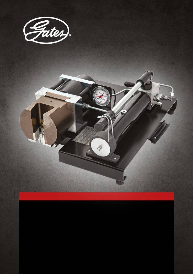
Gates MC2000 Use and care manual

MC2000
OPERATING AND CALIBRATION
INSTRUCTIONS

MC2000 USER GUIDE
2
CONTENTS
1 - CERTIFICATE OF CONFORMITY .................................................................... 3
2 - PRESENTATION ................................................................................................ 4
2. 1 - GENERAL ............................................................................................. 4
2. 2 - CHARACTERISTICS ........................................................................... 4
2. 3 - OPERATING PRINCIPLE .................................................................... 5
2. 3. 1 - Manual Hydraulic Pump ......................................................... 5
2. 3. 2 - Crimping Head…………….................................................... 6
2. 3. 3 - Electrical System .................................................................... 7
3 - OPERATING INSTRUCTIONS .......................................................................... 8
3. 1 - SAFETY ................................................................................................. 8
3. 2 - UNPACKING - INSTALLATION ........................................................ 8
3. 3 - COMMISSIONING - OPERATION ..................................................... 10
3. 4 - CALIBRATION ..................................................................................... 11
3. 5 - POSITION AND FITTING OF THE DIES .......................................... 12
4 - SERVICING AND MAINTENANCE .................................................................. 13
4. 1 - MAINTENANCE .................................................................................. 13
4. 1. 1 - Die Holder Lubrication ......................................................... 13
4. 1. 2 - Checking and Replacing the Oil ............................................ 14
4. 1. 3 - Replacing the Battery ............................................................ 14
4. 1. 4 - Replacing the Bulb ................................................................ 14
4. 2 - SPARE PARTS ..................................................................................... 15
4. 2. 1 - Machine Spare Parts .............................................................. 15
4. 2. 2 - Tooling Spare Parts ............................................................... 15
5 - LIMITED WARRANTY ...................................................................................... 16

MC2000 USER GUIDE
3
1 - CERTIFICATE OF CONFORMITY
EC DECLARATION OF CONFORMITY
The undersigned Company :
GATES
hereby declares that the new equipment, referred to hereafter as :
MC2000 - Serial N° :
conforms with the GATES Specification and with the Hygiene and Safety at Work
Regulations which apply in this case.
Authorised by : Date :
Implemented on : by: place :

MC2000 USER GUIDE
4
2 - PRESENTATION
2. 1 - GENERAL :
You have just acquired a GATES type MC2000 hand operated hydraulic hose and coupling
crimping machine. To this effect, it is important that you follow the operating instructions. This
MC2000 is specially designed to crimp GATES flexible hose assemblies which are commonly
used in industry and agriculture. This documentation includes all the information pertaining to
its operation, use and maintenance.
2. 2 - CHARACTERISTICS:
Crimping Strength : 124 tonnes max calculated.
Hydraulic Pressure : 800 bar
Dimensions : H 310 x W 300 x L 430 mm
Weight : 41 Kg
Crimping Capacity : braided hoses from 3/16" to 1"1/4
spiral hoses 1/4" to 1" non-skive (1"1/4 skived)
Pump : Manual two-speed
Oil Tank : 0.5 litre oil ISO VG 22
Die stroke : 14 mm working stroke and 18 mm maximum stroke
Adjustment: micrometer screw with numerical display and indicating light
Feed: manual hand pump
Feed Stop : cease pumping the manual hand pump when the indicating light
illuminates
Return : by opening the pump by-pass valve, allowing a spring return in
the crimper head
Return Stop : by shutting the pump by-pass valve or when reaching the
mechanical stop
Tooling : sets of GATES dies
These nominal characteristics cannot be used for testing purposes.

MC2000 USER GUIDE
5
2. 3 - OPERATING PRINCIPLE:
This machine comprises 3 assemblies : the manual hydraulic pump, the crimping head with
manual stop and the electrical system.
2. 3. 1 - PUMP :
This provides the hydraulic power required to move the dies during the crimping process.
Its characteristics are specially designed to provide the best compromise between available
power, die movement speed and ease of handling.
Contents and operating principle
The pump comprises (see figure 1) :
- a hinged lever (1)
- a piston (2)
- a valve (3)
- an oil tank (4)
- 2 non-return valves (5)
Figure 1 : Schematic diagram of hydraulic circuit

MC2000 USER GUIDE
6
2. 3. 2 - CRIMPING HEAD:
This is the most technical part of the crimper. With the aid of its dies, it allows the
coupling to be crimped onto the flexible hose.
It comprises the following elements (see figure 2):
- crimping head body (6) - sets of dies (7)
- a hollow piston moved by the oil pressure (8) - eight return springs (5)
- a crimping head flange (3) - a micrometer gauge unit (18)
- a die holder (4)
Figure 2 : Schematic diagram of crimping head and micrometer gauge

MC2000 USER GUIDE
7
Operating Principle
The kinematic crimping principle consists of transforming a rectilinear displacement, i.e.
that of the piston (8), into a radial displacement thus ensuring the crimping process by way
of the dies (7).
Mechanical bonding is achieved through the friction on a slope and a face on the barrel
clamp (3) and a slope (cone) on the piston (8) and the die holders (4). The die holders are
kept together during their travel by means of a spring arrangement.
The main components are made of a special steel and have been subjected to a series of
thermal body and surface treatments, so that they can resist the large loads and wear
through friction is prevented.
Precise guiding is ensured by means of two Teflon-Bronze bearers on the piston (14 & 17).
The piston is sealed by means of two O-rings + anti-extrusion bushes (15 & 16)
2. 3. 3 - THE ELECTRICAL SYSTEM
This system provides the supply power for the end-of-crimping indicator light
It comprises the following elements (see figure 3) :
- a micro-switch (1) - a 9V battery type 6 LR 61 (3)
- a red indicator light (2) - a test push-button (4)
Figure 3 : Electrical diagram
Operating Principle
This system indicates to the operator, by way of a light signal, that the set value on the
micrometer gauge has been reached, i.e. that the final crimping diameter has been attained.

MC2000 USER GUIDE
8
3 - OPERATING INSTRUCTIONS
3. 1 - SAFETY:
Safety glasses must be worn during machine operation.
The crimper must be positioned on a stable bench or frame.
Do not put your hand in the crimping head during its operation.
Do not alter the technical characteristics of the crimper (pressure and other parameters).
3. 2 - UNPACKING - INSTALLATION :
Unpack the machine without destroying the packaging. The machine can only be transported or
received at a later point in time if it is inside its original packaging. Ensure therefore that the
packaging is not damaged when opening it, so that it can be stored.
Lift the box cover, then remove the screws positioned at the bottom of the packaging uprights,
remove the uprights from the box. The crimper is now accessible and can be taken out.
Never hold the machine by its crimping head or by any of its components.
For optimum use and reduced operator fatigue, it is recommended that the crimper is positioned
horizontally on a bench at a height of approximately 0.75m.
Once the machine has been placed on its support, fit the pump handle by inserting it into its
socket situated at the top of the pump body. Secure with butterfly screw.
The warranty will be void if the above unpacking and/or installation procedures are not
followed.

MC2000 USER GUIDE
9
Figure 4 : Identification diagram

MC2000 USER GUIDE
10
3. 3 - COMMISSIONING - OPERATION:
Ref: Figure 4 page 9
- To prepare the machine for crimping, open vent on hand pump by turning the knurled cap
anti-clockwise approx. one full turn until the cap becomes free. (Cap must be tightened
during transit).
N.B. Only remove cap completely when pump requires ‘topping up’ with oil.
-Close the pressure release valve by turning the release valve knob on the hand pump a
clockwise direction (hand tighten only).
-Retract the die holder by opening the valve (1) (anti-clockwise).
- Place the set of dies corresponding to the crimping operation that is required (see Equipment
User Pack - CD).
-Display the value corresponding to the crimping operation that is required on the digital
readout of the gauge (4) (see Equipment User Pack - CD).
- Press the test button (5) to check the battery (6) is not flat and that the indicator light (7)
works correctly.
-Place the hose together with its coupling inside the crimping head (8), whilst respecting the
position of the coupling in relation to the dies if necessary (see Equipment User Pack - CD).
- Close the valve (1) (clockwise).
-Carry out the crimping operation by activating the pump handle (9).
- Stop the crimping process when the indicator light (7) is illuminated.
- Open the valve (1) (anti-clockwise) to open the dies and release the flexible hose assembly.
-Check the crimping diameter with a vernier caliper (7369-0322) and compare the measured
value with the value published in the Equipment User Pack - CD.
A 7 unit variation on the gauge digital readout allows the crimping diameter to vary by
0.1 mm
The gauge values are only provided as a guide to assist in manufacture, only the exact
crimping diameter can guarantee the flexible hose. It is imperative that the diameters
obtained are within the tolerances specified by GATES.

MC2000 USER GUIDE
11
3. 4 - CALIBRATION:
Each machine is factory-calibrated and is ready to operate on delivery. However, the crimper
must be tested each month and whenever the crimped diameter does not match the specified
diameter. The calibration procedure is as follows:
Calibrate using –08 Megacrimp calibration shell 8G (7482-19860-5)
- Place die set no. 33 into the machine.
- Set the gauge to 200.
- Crimp the calibration shell.
- Measure the calibration shell diameter - it should be 26.0mm +/- 0.25mm.
- If the crimped diameter matches the specified diameter, the machine is properly calibrated
-If the crimped diameter does not match the specified diameter, it is necessary to
calibrate the machine as follows:
1 - Calculate in millimeters the difference between the crimped diameter and the
calibration diameter of 26.0 mm
2 - Open the crimping head to its maximum
3 - Unscrew the two M6 screws which hold the stop strip on the back of the piston
(Fig. 2 / 2) then remove the strip (Fig. 2 / 13).
4 - Calibrate the machine using the M6 screw (Fig. 5 / 3) positioned on the strip itself
as follows:
- Measure the dimension (Fig. 5 / 1) of the screw head relative to the strip
Figure 5 : stop strip
- Release the locknut (Fig. 5 / 2)
- Adjust screw (Fig. 5 / 3) by screwing (clockwise) to reduce the crimping
diameter or unscrewing (anti-clockwise) to increase the crimping diameter.
Caution: One turn of the screw or a 1mm change in the dimension
(Fig. 5 / 1) alters the crimping diameter by 0.65 mm
5 - Tighten the locknut (Fig. 5 / 2)
6 - Replace the stop strip at the back using the two M6 screws.
- Crimp another standard calibration shell (-08 MegaCrimp shell) and check the crimping
diameter obtained.
- Recalibrate the machine as described above if the crimping diameter obtained is still
incorrect.

MC2000 USER GUIDE
12
3. 5 – POSITION AND FITTING OF THE DIES:
In order to crimp GATES couplings correctly onto GATES hoses, it is necessary to adhere to the
installation positions of the dies and to the crimping positions below:
or
Fig. 5 Crimping positions and installation of dies for crimping G and GS type couplings

MC2000 USER GUIDE
13
4 - SERVICING AND MAINTENANCE
4. 1 - MAINTENANCE:
4. 1. 1 - DIE HOLDER LUBRICATION
The low friction of the piston on the die holders when crimping is very important. For this
reason, it is necessary to lubricate between the die holder and the piston at regular
intervals. An insufficiently lubricated machine may lead to the piston and the die holders
seizing-up or being damaged. For an effective lubrication, it is very important to apply a
60% concentrated grease with molybdenum bisulfide (this product is provided with the
machine and is available from GATES – 7482-19957).
Lubricate after every 100 crimping operations as indicated below :
Procedure
Lift the back of the die holders from the piston cone, using the lubricating tool provided
(see figure 7) and wipe each of the 8 die holder seatings and the conical surfaceof the
piston. Apply the new grease to this surface using a brush. Also lubricate the die holders’
front face after closing them as far as possible (see figure 8).
Caution: Never use a degreasing agent to remove the old grease from the machine.
Figure 6 : Lubrication of the piston cone seatings
Figure 7 : Lubrication of the die holder front faces

MC2000 USER GUIDE
14
4. 1. 2 – CHECKING AND REPLACING THE OIL
Replace the pump oil once a year.
Procedure: Ref : Figure 4 page 9
- Open the valve (1) on the pump to allow maximum piston back stroke
- Unscrew the filler cap (10) and drain the oil by tilting the machine
- Fill the tank up with new oil (ISO VG 22 recommended) until the level is 5mm from the
top of the tank
- Refit filler cap (10)
4. 1. 3 – REPLACING THE BATTERY
The end-of-crimping indicator light operates by way of a type 6LR 61, 9 Volt battery
Procedure
- Using the lubrication tool, apply slight pressure onto the battery casing tray
- Pull the tray to free the battery
- Replace the 6LR 61 battery, then replace the tray, ensuring correct polarity
Figure 8 : Opening the battery tray Figure 9 : Removal of battery from tray
4. 1. 4 – REPLACING THE BULB
Procedure
- Unclip the red protector from the end-of-crimping indicator light
- Remove the light bulb and replace with a new one
- Clip the red protector for the end-of-crimping indicator light back in place

MC2000 USER GUIDE
15
4. 2 – SPARE PARTS:
Note: Any intervention by the operator on the machine during the warranty period will render
it void.
To order any spare parts, it is necessary to give the part’s reference number, its computer code,
as well as the quantity required.
Example :
Reference : Piston
Computer Code : MC2000-8939
Quantity : 1
4. 2. 1 – MACHINE SPARE PARTS
Item Reference Description P/N Quantity
Item 6 / Fig 2 /Pge 6 MC2000-8937 Crimper Head 7482-19830 1
Item 3 / Fig 2 /Pge 6 MC2000-9356 Flange 7482-19831 1
Item 12 /Fig 2/Pge 6 MC2000-1104 Clamp screw CHC M10x45 12-9 7482-19832 16
Item 8 / Fig 2 /Pge 6 MC2000-8939 Piston 7482-19833 1
Item 4 / Fig 2 /Pge 6 MC2000-8940 Die holder 7482-19834 8
Item 13/ Fig 2/Pge 6 MC2000-8941 Stop Strip 7482-19835 1
Item 5 / Fig 2 /Pge 6 MC2000-8942 Return spring 7482-19836 8
Item 12 /Fig 4/Pge 9 MC2000-9120 Die holder spring 7482-19837 8
Item 17 /Fig 2/Pge 6 MC2000-9084 Carrying piston ring 7482-19838 1
Item 16 /Fig 2/Pge 6 MC2000-9088 Anti extrusion bush D 185 7482-19839 1
Item 16 /Fig 2/Pge 6 MC2000-9085 O-ring D 164.45 x 5.33 7482-19840 1
Item 15 /Fig 2/Pge 6 MC2000-9086 O-ring D 139.07 x 5.33 7482-19841 1
Item 15 /Fig 2/Pge 6 MC2000-9089 Anti extrusion bush D 140 7482-19842 1
Item 6 / Fig 4/ Pge 9 MC2000-211 Battery 9V 7482-19843 1
Item 6 / Fig 4 /Pge 9 MC2000-9091 Battery casing 7482-19844 1
Item 5 / Fig 4 /Pge 9 MC2000-9093 Push button 7482-19845 1
Item 7 / Fig 4/ Pge 9 MC2000-9094 Indicator light 7482-19846 1
Item 7 / Fig 4 /Pge 9 MC2000-9095 Indicator light bulb 7482-19847 1
Item 2 / Fig 4 /Pge 9 MC2000-8557 Manual pump 7482-19848 1
Item 13 /Fig 4/ Pge 9 MC2000-9083 Frame handle 7482-19849 2
Item 18/ Fig 2 /Pge 6 MC2000-9496 Gauge assembly 7482-19850 1
Item 2 /Fig 2 / Pge 6 MC2000-8943 Gauge rod 7482-19851 1
Item 11/Fig 2 /Pge 6 MC5000-4855 Die holder spring 7482-19230 8
Item 1/ Fig 2 / Pge 6 MC5000-21 Rev counter button 7482-19228 1
Item 9 / Fig 2/ Pge 6 MC5000-75 Micro switch 7482-19265 1
Item 10 /Fig 2/Pge 6 MC5000-54 Die retaining pins 7482-19033 8
4. 2. 2 – TOOLING SPARE PARTS
Item 7 /Fig 2/Pge 6 Crimping die sets (See Crimp Data CD for Product Numbers_ 8

MC2000 USER GUIDE
16
5 – LIMITED WARRANTY
GATES guarantee their machines against any faults in materials and workmanship for a period
of 1 year from the date of purchase.
During this Guarantee period, GATES will repair (or replace as the case may be) at no charge to
the customer, all of the defective components, provided that the machine is returned to our
factory. This warranty does not apply if the machine has been damaged accidentally, misused or
undergone any repairs or modifications which were not carried out by GATES. GATES is not
responsible for any injury or damage resulting from direct, indirect or consecutive use of their
machines, nor for their machines after the warranty has been expressly or implicitly broken.
This guarantee replaces all other guarantee, including implicit guarantees.
Every effort has been made to provide exact and exhaustive information in this guide. However,
GATES cannot be held responsible for any errors, annulments and modifications made after
printing has been authorised; or for the use of their products in special or exceptional
circumstances if a GATES representative was not consulted beforehand to verify the intended
use.
For further information, contact :
Gates Hydraulics Ltd Gates Hydraulique S.A. Gates Europe N.V.
Station Road B.P. 14 Dr. Carlierlaan 30
St Neots, Cambs. F - 69881 Meyzieu-Cedex B – 9320 Erembodegem
PE19 1XA, UK TL : +33 (0)4 72 45 12 12 TL : +32 (0)53 / 76 27 11
TL : +44 (0)1480 225000 FX : +33 (0)4 72 02 85 24 FX : +32 (0)53 / 76 27 13
FX : +44 (0)1480 225350
Theworld’smosttrustednamein
belts and hose.
Table of contents
Other Gates Tools manuals
