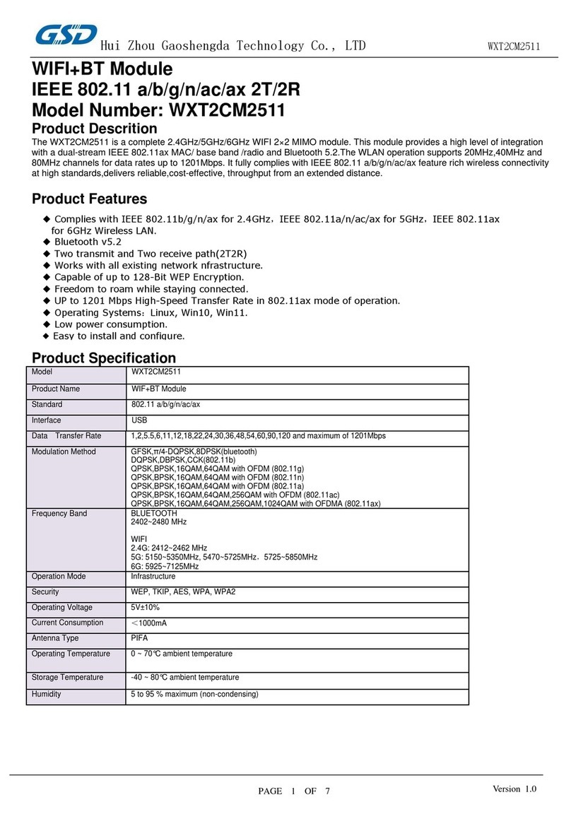
GatesAir Intraplex DS-64NC User manual

GatesAir.com
Intraplex®
DS-64NC Wideband
Synchronous Data Module
DS-64NC Data Module
MA-412, MA-412A, MA-413, MA-413B, MA-414, MA-415,
MA-420, MA-421, MA-427, and MA-428 Module Adapters
Version 9.1
Installation and Operation Manual


Publication Information
©2014 GatesAir, Inc. . Proprietary and Confidential.
GatesAir considers this document and its contents to be proprietary and confidential. Except for making a
reasonable number of copies for your own internal use, you may not reproduce this publication, or any part
thereof, in any form, by any method, for any purpose, or in any language other than English without the written
consent of GatesAir. All others uses are illegal.
This publication is designed to assist in the use of the product as it exists on the date of publication of this manual,
and may not reflect the product at the current time or an unknown time in the future. This publication does not in
any way warrant description accuracy or guarantee the use for the product to which it refers.
GatesAir reserves the right, without notice to make such changes in equipment, design, specifications,
components, or documentation as progress may warrant to improve the performance of the product.
GatesAir reserves the right, without notice to make such changes in equipment, design, specifications,
components, or documentation as progress may warrant to improve the performance of the product.
Trademarks
AudioLink PLUS™, HD Link™, IntraGuide®, Intraplex®, NetXpress™, NetXpress LX™, STL PLUS®, SynchroCast®, and
SynchroCast3™ are trademarks of GatesAir Corporation. Other trademarks are the property of their respective
owners.
Customer Service Contact Information
www.gatesair.com
GatesAir
3200 Wismann Lane
Quincy, Il 62305 USA
For Technical Support including Service, Training, Repair and Service Parts:
www.gatesair.com/services/technical-support.aspx
Americas:
24/7 Technical Support +1 217 222 8200
Email [email protected]
Europe, Middle East and Africa:
24/7 Technical Support +1 217 222 8200
Email [email protected]
Asia:
24/7 Technical Support +1 217 222 8200
Email [email protected]

*Version numbers usually correspond to software releases. If the manual versions differ in number from the release, the front page shows both
the manual version and the release version.

No header here
GatesAir i
Intraplex Products
Table of Contents
Section 1 – Introduction................................................................ 1-1
Section 2 – Functional Description ................................................ 2-1
2.1 Timing...........................................................................................2-1
2.2 Buffering .......................................................................................2-1
2.3 Time Slot Assignment......................................................................2-3
2.4 Loopbacks .....................................................................................2-3
2.4.1 Local (Payload) Loopback...................................................................... 2-3
2.4.2 Equipment Loopback............................................................................ 2-3
2.4.3 Remote Loopback ................................................................................ 2-4
2.5 Diagnostics ....................................................................................2-4
2.5.1 Test Pattern Generator......................................................................... 2-4
2.5.2 Performance Registers.......................................................................... 2-4
2.6 Alerts and Alarms ...........................................................................2-4
2.6.1 Alerts................................................................................................. 2-4
2.6.2 Alarms............................................................................................... 2-5
2.7 Switches and Indicator Lights ...........................................................2-5
2.7.1 Card Address Setup ............................................................................. 2-8
2.7.2 Starting Time Slot Selection.................................................................. 2-9
2.7.3 Loopback Mode Selection.................................................................... 2-11
2.7.4 Test Pattern Generator Setup .............................................................. 2-11
2.7.5 Transmit Mode Selection..................................................................... 2-12
2.7.6 Data Rate Selection ........................................................................... 2-12
2.8 Remote Control Interface............................................................... 2-13
2.8.1 IntraGuide Software........................................................................... 2-13
2.8.2 ISiCL ............................................................................................... 2-13
2.8.2.1 P Codes................................................................................................ 2-13
2.8.2.2 S Codes ............................................................................................... 2-16
Section 3 – Installation & Configuration........................................ 3-1
3.1 Inspection......................................................................................3-1
3.2 Preliminary Configuration.................................................................3-1
3.3 Installation & Local/Remote Configuration ..........................................3-3
3.4 Mounting .......................................................................................3-3
Section 4 – Testing & Troubleshooting .......................................... 4-1
4.1 Troubleshooting with the Internal Test Pattern Generator .....................4-1
4.2 Troubleshooting with an External Data Test Set...................................4-1
Section 5 – Specifications.............................................................. 5-1

DS-64NC Synchronous Data Module Table of Contents
Version 9.1
ii GatesAir
Intraplex Products
Appendix A – Module Adapters for the DS-64NC Module...............A-1
A.1 37-pin Connector Module Adapters (MA-412, 412A, 413, 413B, 4-14 and
415) ....................................................................................................A-1
A.2 X.21 Module Adapters (MA-420 and MA-421)......................................A-7
A.3 MA-427 LAN Bridge Module Adapter...................................................A-9
A.3.1 Installation and Operation................................................................... A-10
A.3.2 Troubleshooting ................................................................................ A-12
A.4 MA-428 Enhanced LAN Bridge Module Adapter .................................. A-13
A.4.1 MA-428 Operation ............................................................................. A-14
A.4.2 MA-428 Troubleshooting..................................................................... A-17
Appendix B – Data Rate Selection Table ........................................B-1
Figures
Figure 2-1. DS-64NC Module, Functional Diagram.................................................................... 2-2
Figure 2-2. Loopbacks ......................................................................................................... 2-3
Figure 2-3. DS-64NC Module, Front View................................................................................ 2-5
Figure 2-4. DS-64NC Module, Top View.................................................................................. 2-6
Figure 2-5. Data Rate Increments – Switch Bank S4 ...............................................................2-12
Figure 3-1. DS-64NC Module, Top View.................................................................................. 3-4
Figure A-1. MA-412, MA-412A, MA-413, MA-413B (DCE) Module Adapters .................................. A-1
Figure A-2. MA-414 and MA-415 (DTE) Module Adapters .......................................................... A-2
Figure A-3. Signal Flow Between an MA-412/MA-412A (DCE) and RS-449 DTE Equipment............. A-3
Figure A-4. Signal Flow Between an MA-413/MA-413B (DCE) and V.35 DTE Equipment................. A-4
Figure A-5. Signal Flow Between an MA-414 (DTE) and RS-449 DCE Equipment........................... A-5
Figure A-6. Signal Flow Between an MA-415 (DTE) and V.35 DCE Equipment............................... A-6
Figure A-7. Jumper Location and Settings on MA-412/MA-412A/MA-413/MA-413B Module Adapters A-7
Figure A-8. MA-420 X.21 DCE Module Adapter ........................................................................ A-8
Figure A-9. MA-421 X.21 DTE Module Adapter......................................................................... A-8
Figure A-10. MA-427 LAN Bridge Module Adapter................................................................... A-11
Figure A-11. Pins 1 and 8 on RJ-45 Connector and MA-427 Module Adapter............................... A-12
Figure A-12. MA-428 Module Adapter................................................................................... A-14
Figure A-13. Pins 1 and 8 on RJ-45 Connector and MA-428 Module Adapter............................... A-14

Table of Contents DS-64NC Synchronous Data Module
Version 9.1
GatesAir iii
Intraplex Products
Tables
Table 2-1. Indicator Lights ................................................................................................... 2-7
Table 2-2. Switch Settings ................................................................................................... 2-7
Table 2-3. Card Address Setting – S1 .................................................................................... 2-9
Table 2-4. Starting Time Slot Selection in T1 Multiplexer – S2, Positions 4-8 ..............................2-10
Table 2-5. Starting Time Slot Selection in E1 Multiplexer – S2, Positions 4-8 ..............................2-10
Table 2-6. Loopback Settings – S3, Positions 1 & 2.................................................................2-11
Table 2-7. Test Pattern Settings – S3, Positions 3-5................................................................2-11
Table 2-8. Transmit Settings – S3, Positions 7 & 8..................................................................2-12
Table 2-9. Data Rate Setting Examples – S4..........................................................................2-12
Table 2-10. Remote Configuration Settings – P Codes .............................................................2-14
Table 2-11. Remote Status Messages – S Codes.....................................................................2-17
Table 2-12. Approximate FIFO Depth Calculation....................................................................2-19
Table A-1. Configuration Jumpers on MA-420 and MA-421 Module Adapters ................................ A-9
Table A-2. MA-420 and MA-421 Pin Outputs ........................................................................... A-9
Table A-3. MA-427 Switch Settings...................................................................................... A-10
Table A-4. Straight-Through and Crossover RJ-45 UTP Cable Pin Connections............................ A-11
Table A-5. MA-427 LAN Bridge Indicator Lights ..................................................................... A-12
Table A-6. Problems and Solutions for MA-427 LAN Bridge Module Adapter ............................... A-13
Table A-7. MA-428 Switches, Connectors, and Jumpers .......................................................... A-15
Table A-8. Cables Supported by MA-428 Module Adapter ........................................................ A-15
Table A-9. MA-428 DIP Switch Settings................................................................................ A-15
Table A-10. MA-428 Combinations of Auto-Negotiation and Forced Modes................................. A-16
Table A-11. MA-428 Indicator Light Descriptions ................................................................... A-16
Table A-12. MA-428 Alarm Conditions.................................................................................. A-17
Table A-13. Troubleshooting Possible Problems and Solutions.................................................. A-17
Table A-14. Auto-Negotiation/Forced Mode Combinations ....................................................... A-18
Table B-1. DS-64NC Module Data Rate Selection ..................................................................... B-1

No header here
iv GatesAir
Intraplex Products
This page is left blank intentionally.

GatesAir 1-1
Intraplex Products
Section 1 – Introduction
This manual describes the setup and installation procedures for the Intraplex DS-64NC wideband
synchronous data module. Experienced users may go directly to the tables in Section 2 for
configuration data. The specific multiplexer operation manuals contain additional information about
using channel modules in Intraplex multiplexers.
The DS-64NC module is a synchronous data channel module that can operate at a selectable data
rate. The rate can be any multiple of 8 kbps, with a maximum limit that depends on the multiplexer
type. Ranges are from 8 kbps to
●1.536 Mbps in T1 multiplexers and T1-based variable rate multiplexers.
●1.984 Mbps in 2 MB multiplexers.
●2.040 Mbps in 2 MB-based variable rate multiplexers.
Features include
●User-selectable data rate.
●Fully independent send and receive timing (at the same nominal rate in both directions).
●Timing output to allow synchronization of the multiplexer to the DS-64NC module’s receive clock
signal.
●One-way or full-duplex operation.
●Choice of RS-449 or V.35 interface.
●Local and remote loopbacks.
●Clear channel operation for AMI networks.
●A test pattern generator and error detector for one-way or loopback testing.
●Contiguous or alternating time slot assignment.
●2 MB multiplexers only: Time slot 16 can be skipped for systems using CAS signaling.
●Remote control configuration and status reporting.
●Selectable transmit/receive direction.
●Optional deep buffers for plesiochronous operation.


1-2 GatesAir
Intraplex Products
This page is left blank intentionally.


GatesAir 2-1
Intraplex Products
Section 2 – Functional Description
2.1 Timing
Transmit-side and receive-side timing are completely independent of each other. The module includes
two DDS (direct digital synthesis) clock generators that have a maximum jitter output of 30.52 nS
peak-to-peak (6%, or 0.06 UI, maximum at 1.984 Mbps).
The timing outputs can be set to any integer multiple of 8000 bits per second (8 kbps). The maximum
data rate is determined by the number of payload time slots in the multiplexed signal. In a T1 or T1-
based variable rate system there are 24 time slots, for a maximum data rate of 1.536 Mbps. In a 2 MB
system there are 31 time slots, or 30 time slots if CAS multiframe is in use, giving maximum data
rates of 1.984 Mbps or 1.920 Mbps respectively. A 2 MB-based variable rate system provides a
maximum data rate of 2.040 Mbps.
The module also includes a master-clock synthesizer (at either 1.544 or 2.048 MHz) that is frequency-
locked to one of the timing inputs at the data interface. This synthesizer allows network timing to
follow the data rate precisely, within the tolerance specified by the network.
2.2 Buffering
The transmit-side and receive-side each have first-in, first-out (FIFO) buffers with a depth of 12,000
bits. The starting depth of these buffers can be set either to 256 bits for normal synchronous
operation, or to half the full depth (6000 bits) for plesiochronous operation. The buffer can be
recentered by remote control.
The current depth of each FIFO (transmit side and receive side) is maintained in a performance
register, which can be read by remote access (Section 2.5.2). This register may be used to implement
“intelligent” reset algorithms; for example, “reset at midnight unless already within 1/8 of center.”
This status information is available via the multiplexer’s remote port.

DS-64NC Synchronous Data Module 2 – Functional Description
Version 9.1
2-2 GatesAir
Intraplex Products
Double
Buffer
FIFO
TDM BUS
Format
Double
Buffer
FIFO
Format
TD
AT
A
TC
LK
TO
HD
RO
HD
RC
LK
RD
AT
A
Serial
Port 0
Serial
Port 1
Serial
Port 1
Serial
Port 0
TX
BUFF
BIT
NE
ERR
RECEIVE
DSP
TRANSMIT
DSP
TIMESLOT (S2/pos 4-8)
ALT (S2/pos 3)
CAS (S6/pos 1)
DATA RATE
(S4/pos 1-10)
56K (S2/pos 2)
BUFF (S2/pos 1)
INTRAPLEX
LOGIC ARRAY 2
Configuration
and Control
LPBK
FAIL
S
C
RX OUT
TX IN
Timing
Synth
(Part of
ILA 1)
Timing
Connector
Reference Clock
to Common Module
Ha
nd
sh
ak
e
SRVC OFF (S5/pos 4)
REMOTE (S5/pos 3)
TERM (S5/pos 1)
TX MODE (S3/pos 7-8)
RX ON (S3/pos 6)
LPBK (S3/pos 1-2)
TEST (S3/pos 3-5)
E1 (S6/pos 2)
SCB ADDR (S1/pos 1-6)
SRVC
Timing Out
Timing In
Data In
Timing Out
Data Out
INTRAPLEX
LOGIC ARRAY 1
Transmit
Clock Synch
Receive
Clock Synch
RS-449 or V.35 Connector
Figure 2-1. DS-64NC Module, Functional Diagram

2 – Functional Description DS-64NC Synchronous Data Module
Version 9.1
GatesAir 2-3
Intraplex Products
2.3 Time Slot Assignment
The module may be placed in either of two modes: 7 bits per time slot (56xN kbps) or 8 bits per time
slot (64xN kbps). In the 7-bit mode, the 8th bit is set to “1” and is monitored for errors at the receive
side (Section 2.5). You specify the starting time slot number and whether adjacent or alternate time
slots are to be used.
Normally, adjacent time slots are used, but certain sub-rate services require the use of alternate time
slots. Also, you can use an alternate time slot assignment to solve ones-density problems in 64xN
systems when the payload includes other kinds of channels that can be interleaved with the data from
this module. Wrap-around of time slot assignments is not allowed; if the starting time slot is set too
high for the requested data rate, the module does not operate. In 2 MB applications, you can skip time
slot 16 to allow for CAS signaling.
2.4 Loopbacks
Loopbacks connect the data and timing signals from one direction to the other direction in place of the
payload. The DS-64NC module provides three types of loopbacks:
●Local (payload)
●Equipment
●Remote
Loopbacks do not force the module into full-duplex operation if the module is not operating in full-
duplex already. In a half-duplex configuration, a local (payload) loopback works, but an equipment
loopback does not.
Figure 2-2. Loopbacks
2.4.1 Local (Payload) Loopback
A local (payload) loopback exercises channel module logic up to the bus interface. Incoming data from
the RS-449 or V.35 port is looped back to the same port. This loopback may only be activated at the
near end (by switch or remotely). A local loopback is activated in the module at Location 1 (Figure 2-
2). Receive timing becomes frequency-locked to transmit timing. This loopback type is used to check
the performance of the module itself.
2.4.2 Equipment Loopback
An equipment loopback turns receive-side data around to the transmit side at the line interface from
the near end (Figure 2-2). If the backplane buses in the shelf are not frequency-locked when the
equipment loopback is in effect, the transmit-side FIFO spills periodically.

DS-64NC Synchronous Data Module 2 – Functional Description
Version 9.1
2-4 GatesAir
Intraplex Products
2.4.3 Remote Loopback
A remote loopback also turns receive-side data around to the transmit side at the line interface. Use
this loopback to check out the data transmission link. Activating a local equipment loopback is
equivalent to the far end shelf requesting a far end loopback; that is, a local equipment loopback
returns the receive data signal back to the far end of the circuit.
You can also initiate a remote loopback at one end to check out the DS-64NC module at the other end.
Activating the remote loopback at the near end (Location 1 in Figure 2-2) causes a loopback in the
DS-64NC module at the far end (Location 2). Activation and deactivation of the remote equipment
loopback is implemented in-band by replacing the payload data with fixed loop-up and loop-down
signals, respectively. As in the case of the equipment loopback, if the backplane buses in the shelf are
not frequency-locked when the remote loopback is in effect, the transmit-side FIFO spills periodically.
2.5 Diagnostics
2.5.1 Test Pattern Generator
The module includes test-pattern generators on both the transmit and receive sides, along with a
synchronizer on the receive side. The payload may be replaced with a test pattern for diagnostic
purposes, either in a one-way end-to-end mode or a loopback mode.
A front-panel indicator light shows bit errors, which are accumulated in a performance register
(Section 3 – Installation Configuration). Section 2.7.4 – Test Pattern Generator Setup gives test
pattern settings.
2.5.2 Performance Registers
The DS-64NC module maintains performance registers that keep track of seven conditions and event
histories:
●Current transmit-side FIFO depth
●Transmit-side FIFO underrun count since last reset
●Transmit-side FIFO overrun count since last reset
●Current receive-side FIFO depth
●Receive-side FIFO underrun count since last reset
●Receive-side FIFO overrun count since last reset
●Receive-side bit error count since last reset
These registers can be read and reset via the remote port on the multiplexer, using P codes and S
codes with the Intraplex Simple Command Language (ISiCL). Section 2.8.2 gives details on these
codes. The multiplexer operation manual gives a fuller description of ISiCL.
2.6 Alerts and Alarms
This section discusses conditions which cause the DS-64NC module to report ALERT and ALARM
signals to the shelf common module.
2.6.1 Alerts
There are two types of alerts:
●Configuration error
This error indicates that you have selected a combination of data rate and starting time slot that
does not permit all data to fit into the time slots available, given the current settings for system
usage (T1 or 2 MB) and payload bits per time slot (56 or 64).

2 – Functional Description DS-64NC Synchronous Data Module
Version 9.1
GatesAir 2-5
Intraplex Products
●Input/output pin error
This error is detected on one of these pins:
•Transmit clock out
•Receive clock out
•Receive data out
•Handshake out
2.6.2 Alarms
An alarm registers when the DS-64NC module detects a hardware or software failure.
2.7 Switches and Indicator Lights
The DS-64NC module contains six switch banks and nine indicator lights (Figures 2-3 and 2-4).
1
2
3
4
5
6
7
8
1
2
3
4
SRVC
light
TIMESLOT
BUFF
56K
ALT
1
2
3
4
5
6
7
8
LPBK
TEST
RX ON
TX MODE
DATA
RATE (behind indicator lights)
REMOTE
TERM
AUX
OFF
S1 & S6:
S2
S3
S4
S5
LOCATED
BEHIND S2 & S5
FAIL Light
FE ERR Light
NE ERR Light
RX SYNC Light
RX OUT Light
LPBK Light
TX BUFF Light
TX IN Light
Figure 2-3. DS-64NC Module, Front View

DS-64NC Synchronous Data Module 2 – Functional Description
Version 9.1
2-6 GatesAir
Intraplex Products
Figure 2-4. DS-64NC Module, Top View
JP5
JP6
JP3
JP4
Jumpers only
on Rev D board

2 – Functional Description DS-64NC Synchronous Data Module
Version 9.1
GatesAir 2-7
Intraplex Products
Note: Jumpers 3-6 appear on Rev D of the DS-64NC module board. Leave these jumpers in the
same position as they were set at the factory (Figure 2-4). These jumpers do not appear in
previous or newer revisions of this board.
Table 2-1 describes the indicator lights. Table 2-2 summarizes the switch functions. Tables 2-3
through 2-9 explain functions which use multiple switches and thus have more than two possible
settings.
Remember these definitions for light descriptions:
●On – The light is on steadily.
●Blink – The light turns on and off in a rhythmic, one-half second pulse.
●Flash – The light turns on and then off in an erratic flicker.
Table 2-1. Indicator Lights
Indicator
Light Color Description
TX IN Green Transmit in; on when transmit data activity is detected
TX BUFF Yellow Transmit buffer; flashes when the transmit FIFO buffer overruns or underruns
LPBK Yellow Loopback; on when local equipment loopback is active; blinks when equipment loopback
is activated from the far end
RX OUT Green Receive out; on when receive data activity is detected
RX SYNC Red For future use
NE ERR Yellow Near end error; flashes when a near end error is detected
FE ERR Yellow For future use
FAIL Red Failure; on when DSP failure occurs
SVRC Green Service; on when the module is in service (service switch is turned on or the module is
remotely activated).
Blinks if a configuration error is detected; that is, you have selected a combination of data
rate and starting time slot that do not permit all data to fit into the time slots available,
given the current settings for system usage (T1 or 2MB) and bits per time slot (56 or 64).
The module remains out of service while a configuration error exists.
Table 2-2. Switch Settings
Switch #/
Position Label Setting Description
S1/1-6 SCB ADDR Table 2-3 Set the module address (for remote access use).*
S2/1 BUFF UP Set starting depth for the transmit and receive buffers to 256 bits
(for synchronous operation).
DOWN Set starting depth for the transmit and receive buffers to 6000 bits
(for plesiochronous operation).
S2/2 56K UP Set to 64 kbps per time slot.
DOWN Set to 56 kbps per time slot.**
S2/3 ALT UP Set to use sequential time slots.
DOWN Set to use alternating time slots.
S2/4-8 TIMESLOT Tables
2-4 and 2-5 Set starting time slot number.
* Remove the DS-65NC module before changing the SCB address.
** When using 56 kbps per time slot, allow for the additional number of time slots needed to hold the
total amount of data. The number of time slots affect the choice of starting time slot. Appendix B

DS-64NC Synchronous Data Module 2 – Functional Description
Version 9.1
2-8 GatesAir
Intraplex Products
lists the number of time slots required for each available data rate, when operating at either 64
kbps or 56 kbps per time slot.
Table 2-2. Switch Settings (continued)
Switch #/
Position Label Setting Description
S3/1-2 LPBK Table 2-6 Set loopback mode.
S3/3-5 TEST Table 2-7 Set test pattern.
S3/6 RX ON UP Set to turn the receive side of the module off.
DOWN Set to turn the receive side of the module on.
S3/7 TX MODE Table 2-8 Set the transmit mode for the module.
S4/1-10 DATA RATE Table 2-9 Set the data rate for the module.
S5/1 TERM UP May be used when the module is in a drop and insert multiplexer.*
DOWN Required setting in a terminal multiplexer.
S5/2 AUX UP NORMAL – External timing output not active.
DOWN External timing output active.
S5/3 REMOTE UP Set module for local configuration.
DOWN Set module for remote configuration.
S5/4 SRVC UP Set service on (module is active).
DOWN Set service off (module is inactive).
S6/1 CAS ON Reserves time slot 16 for signaling. Set this switch on only when
the module is in an E1 (2 MB) multiplexer using CAS signaling.
OFF Time slot 16 is available for payload.
S6/2 E1 ON Set the module for use in an E1 (2MB) multiplexer (2.048 MHz bus
clock).
OFF Set the module for use in a T1 multiplexer (1.544 MHz bus clock).
* Set this switch UP to transmit and receive via the DI-B common module in a drop and insert
multiplexer, and DOWN to use in a terminal multiplexer or to transmit and receive via the DI-A
common module in a drop and insert multiplexer. The drop and insert operation section in your
multiplexer operation manual gives additional information.
In addition to the switches on the module itself, some of the module adapters that can be used with
the DS-64NC module have jumpers that can be set to different positions for different functions.
Appendix A gives guidelines on setting these jumpers.
2.7.1 Card Address Setup
For remote access, each channel module in an Intraplex remotely controllable shelf must have a
distinct card address. Valid card addresses are the numbers 1 to 36. Your multiplexer operation
manual gives details on using the system’s remote access and configuration features.
This manual suits for next models
10
Table of contents
Other GatesAir Control Unit manuals
Popular Control Unit manuals by other brands

salmson
salmson Cleanskid Series Installation and starting instructions

Powers
Powers HydroGuard e427 Series Technical instructions
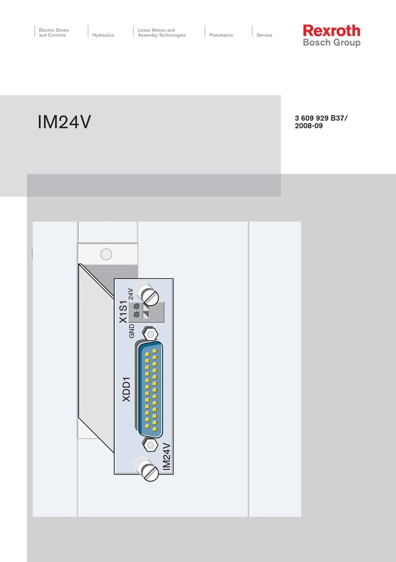
Bosch
Bosch Rexroth IM24V manual

GiBiDi
GiBiDi AS01500 Instructions for installations
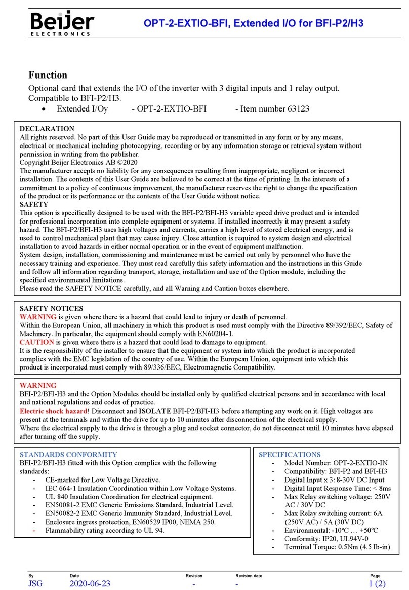
Beijer Electronics
Beijer Electronics OPT-2-EXTIO-BFI manual
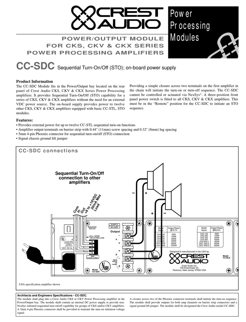
Crest Audio
Crest Audio CC-SDC datasheet
