GatesAir Intraplex VF-40 User manual

GatesAir.com
Intraplex®
VF-40 Four-Port E&M Voice Module
Installation & Operation Manual
VF-40 Voice Module
MA-311 Ethernet Module Adapter
Version 1.11
Installation and Operation Manual


Publication Information
©2014 GatesAir, Inc. . Proprietary and Confidential.
GatesAir considers this document and its contents to be proprietary and confidential. Except for making a
reasonable number of copies for your own internal use, you may not reproduce this publication, or any part
thereof, in any form, by any method, for any purpose, or in any language other than English without the written
consent of GatesAir. All others uses are illegal.
This publication is designed to assist in the use of the product as it exists on the date of publication of this manual,
and may not reflect the product at the current time or an unknown time in the future. This publication does not in
any way warrant description accuracy or guarantee the use for the product to which it refers.
GatesAir reserves the right, without notice to make such changes in equipment, design, specifications,
components, or documentation as progress may warrant to improve the performance of the product.
GatesAir reserves the right, without notice to make such changes in equipment, design, specifications,
components, or documentation as progress may warrant to improve the performance of the product.
Trademarks
AudioLink PLUS™, HD Link™, IntraGuide®, Intraplex®, NetXpress™, NetXpress LX™, STL PLUS®, SynchroCast®, and
SynchroCast3™ are trademarks of GatesAir Corporation. Other trademarks are the property of their respective
owners.
Customer Service Contact Information
www.gatesair.com
GatesAir
3200 Wismann Lane
Quincy, Il 62305 USA
For Technical Support including Service, Training, Repair and Service Parts:
www.gatesair.com/services/technical-support.aspx
Americas:
24/7 Technical Support +1 217 222 8200
Email tsup[email protected]
Europe, Middle East and Africa:
24/7 Technical Support +1 217 222 8200
Email [email protected]
Asia:
24/7 Technical Support +1 217 222 8200
Email [email protected]

Version Date Revisions Made Section Pages Editor
1 3/13/09 Created manual. All All LD
1.1 6/21/11 Updated Figure 2-3 for emphasis feature.
Updated Figure 2-4 with labeled switches.
Updated Table 2-1 for emphasis feature.
Corrected Table 2-3 jumper settings.
2.6 2-4
2-5
2-6
2-7
LD
Updated Table 2-6 for current P codes.
Updated Tables 2-7 and 2-8 for P code changes. 2.7.1 2-11 – 2-13
2-15
Added section for TIA-603C emphasis option. 2.8 2-17 – 2-8
Added warning about hot inserting module adapters. 3.2, A 3-1, A-2
Added Figure A-2 and information on M-input leads. A A-1
1.11 6/24/11 Changed all occurrences of “TYPE 143” to “TYPE 142.” 2.7
3.2
2-9, 2-10,
2-15
3-2
LD
*Version numbers usually correspond to software releases. If the manual versions differ in number from the release, the front page shows both
the manual version and the release version.

No header here
GatesAir i
Intraplex Products
Table of Contents
Section 1 – Introduction................................................................ 1-1
Section 2 – Functional Description & Setup ................................... 2-1
2.1 Transmit Side.................................................................................2-1
2.2 Receive Side ..................................................................................2-1
2.3 Alerts/Alarms .................................................................................2-3
2.4 Loopbacks .....................................................................................2-3
2.5 Drop and Insert Operation................................................................2-3
2.6 Indicator Lights and Controls............................................................2-4
2.7 Remote Control Interface.................................................................2-8
2.7.1 P Codes.............................................................................................. 2-9
2.7.2 S Codes ........................................................................................... 2-15
2.8 TIA-603C Emphasis Option............................................................. 2-17
Section 3 – Installation ................................................................. 3-1
3.1 Inspection......................................................................................3-1
3.2 Configuration .................................................................................3-1
3.3 Mounting .......................................................................................3-2
Section 4 – Testing & Troubleshooting .......................................... 4-1
4.1 Local versus Remote Loopback .........................................................4-1
4.2 VF-40 Loopback Setup Procedure ......................................................4-1
Section 5 – Specifications.............................................................. 5-1
Appendix A – MA-311 Module Adapter for the VF-40 Module.........A-1

Intraplex VF-40 Voice Module Table of Contents
Version 1.11
ii GatesAir
Intraplex Products
Figures
Figure 2-1. VF-40 Voice Module, Block Diagram....................................................................... 2-2
Figure 2-2. Example of Three-Site System Using Drop and Insert .............................................. 2-3
Figure 2-3. VF-40 Voice Module, Front View............................................................................ 2-4
Figure 2-4. VF-40 Voice Module, Top View .............................................................................. 2-5
Figure 2-6. Transmit Channel – Effect of P Code.....................................................................2-14
Figure 2-7. Receive Channel – Effect of P Code.......................................................................2-14
Figure 2-5. TIA-603C Emphasis Measurement........................................................................2-18
Figure 4-1. Local versus Remote Loopback ............................................................................. 4-1
Figure A-1. 50-pin Connector................................................................................................ A-1
Figure A-2. M-Input Leads....................................................................................................A-1
Tables
Table 2-1. Configuration Switches ......................................................................................... 2-6
Table 2-2. Active Channel Selection – SW2, Positions 3 & 4....................................................... 2-6
Table 2-3. Input/Output Level Jumper Settings ....................................................................... 2-7
Table 2-4. T1 and E1 Starting Time Slot Selection - SW1, Positions 1-5 ...................................... 2-8
Table 2-5. Module Address Setting – SW3 .............................................................................. 2-9
Table 2-6. Remote Configuration Settings (P Codes) ...............................................................2-11
Table 2-7. Transmit Channel Suggested P Codes to Achieve Desired dB Gain..............................2-15
Table 2-8. Receive Channel Suggested P Codes to Achieve Desired dB Gain................................2-15
Table 2-9. Remote Status Messages (S Codes).......................................................................2-16
Table 3-1 Sample VF-40 Response To A CONFIG? Query........................................................... 3-2
Table A-1. Pin Assignments on the MA-311 Module Adapter ...................................................... A-1

No header here
GatesAir 1-1
Intraplex Products
Section 1 – Introduction
This manual describes the setup and installation procedures for the Intraplex VF-40 Voice Frequency
Module. Experienced users may refer directly to the tables in Section 2 for configuration data. Your
Intraplex multiplexer operation manual gives additional information about this system.
The VF-40 four-port voice frequency module is designed to use in the Intraplex terminal and drop and
insert multiplexers and other Intraplex communications products. The voice interface is full duplex,
four-wire with PCM (Pulse Code Modulation) coding, allowing four voice channels to be carried in four
64 kbps time slots on T1 and other digital communications facilities.
Each VF-40 module provides high quality voice characteristics. The module has extended-range input
and output signal level adjustments to facilitate interfaces in most four-wire applications. The VF-40
voice module includes these features:
●Extended low frequency range (5-300 Hz range)
●One to four independent channels may be active simultaneously
●Two independent normally open/normally closed contacts per channel
●Remote control configuration and status reporting
●Selectable transmit/receive direction for use in drop and insert systems
●Input/output gain adjustment


No header here
1-2 GatesAir
Intraplex Products
This page is left blank intentionally.


No header here
GatesAir 2-1
Intraplex Products
Section 2 – Functional Description & Setup
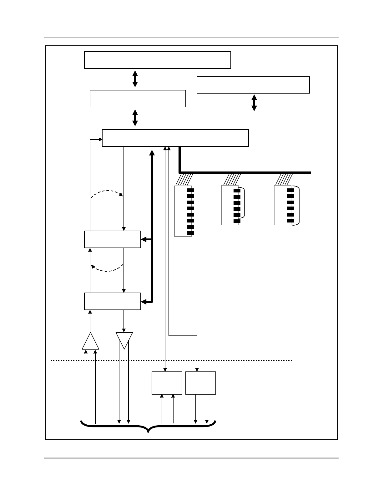
This section’s descriptions refer to one channel; each of the four channels on this module operates
identically. Figure 2-1 shows a simplified block diagram of the VF-40 module.
2.1 Transmit Side
Voice input is through the module adapter at the rear of the shelf. The input signal goes to a balanced
input buffer. The input buffer output goes to an amplifier stage and then passes through an electronic
level control, which allows the input level to be adjusted up or down from the nominal setting in <0.1
dB increments. The normal factory-set input level is 0 dBm, referenced to 600 ohms and clipping
begins at an input level of +3.0 dBm. Switches on the module allow the nominal input level to be set
to -16 dBm. The control output then passes to the PCM CODEC, which converts it to an eight-bit
digital signal using µ-law coding.
The Field Programmable Gate Array (FPGA) multiplexes the M-Lead signal together with the eight-bit
output of the PCM encoder and places the resulting bitstream into the user-selectable time slot on the
backplane for transmission in the desired direction. Each channel occupies one time slot; you select
the time slot for Channel 1, and each additional active channel occupies the next sequential time slot.
2.2 Receive Side
The FPGA gets the input signal from the appropriate time slot on the backplane and demultiplexes it.
Intraplex VF-40 Voice Module 2 – Functional Description & Setup
Version 1.11
2-2 GatesAir
Intraplex Products
Figure 2-1. VF-40 Voice Module, Block Diagram
TDM Bus
Serial Control Bus
Drivers & Receivers
FPGA
PCM CODEC
Level Control
1
2
3
4
5
6
7
8
TONE
SP0
TS1
TS0
TERM
SIG OFF
REMOTE
SRVC
SELECT
TIME SLOT SET SCB
ADDRESS
LBACK
1
2
3
4
5
6
1
2
3
4
5
6
SELECT
TIME SLOT SET SCB
ADDRESS
1
2
3
4
5
6
7
8
M Lead
Detect
E Lead
Driver
Channel 1 _ _ _ _ _ Chan. 2 _ _ Chan. 3 _ _ Chan. 4
Module Adapter
VF-40 Module
M-A Input
M-B Input
E-A Output
E-B Output
Local
Loopback
Remote
Loopback

2 – Functional Description & Setup Intraplex VF-40 Voice Module
Version 1.11
GatesAir 2-3
Intraplex Products
The PCM CODEC converts the eight-bit digital signal back to an analog audio signal and passes it to an
electronic level control, which allows the output level to be adjusted up or down in <0.1 dB
increments.
The audio output passes to an amplifier stage and finally to the output connectors on the module
adapter. Switches on the module allow the nominal output level to be set to +7 dBm.
2.3 Alerts/Alarms
The VF-40 module reports no module-level ALERT or ALARM signals to the shelf common module.
2.4 Loopbacks
The VF-40 module provides two loopback types:
●Local loopback of all four channels, used for testing the operation of the module during initial
installation
●Remote loopback of each channel individually, used when troubleshooting channel problems
Figure 2-3 shows these loopback locations. Section 4 – “Testing and Troubleshooting” provides
procedures for using these loopbacks.
2.5 Drop and Insert Operation
A drop and insert multiplexer operates at a central point on a three- (or more) point system. In Figure
2-2, Site 2 has a drop and insert multiplexer whose DI/A port is connected to the transmission line to
Site 1 and whose DI/B port is connected to the transmission line to Site 3. Individual payload channels
may connect Sites 1 and 2, 1 and 3, or 2 and 3.
Note: In the drop and insert multiplexer at Site 2, a VF-40 module can be set to transmit and
receive through the DI-A port (toward Site 1) or the DI-B port (toward Site 3) but not both.
When a VF-40 module is installed in a terminal multiplexer (Site 1 or Site 3), its TERM switch must be
set DOWN. However, when it is installed in a drop and insert multiplexer (Site 2), the TERM switch
setting must be DOWN to transmit or receive through the DI/A port (toward Site 1) and UP to transmit
or receive through the DI/B port (toward Site 3).
Site 2
Drop and Insert Multiplexer
Through Channels
Site 3
Terminal
Multiplexer
To/From
Site 1
(TERM
Switch
DOWN)
To/From
Site 3
(TERM
Switch
UP)
Drop and
Insert
Channels
D/I
AD/I
B
Site 1
Terminal
Multiplexer
To/From
Site 2
(TERM
Switch
DOWN)
T1 or
Aggregate
Circuit
To/From
Site 3
(TERM
Switch
DOWN)
To/From
Site 1
(TERM
Switch
DOWN)
To/From
Site 2
(TERM
Switch
DOWN)
V
F
4
0
V
F
4
0
V
F
4
0
V
F
4
0
V
F
4
0
V
F
4
0
T1 or
Aggregate
Circuit
Figure 2-2. Example of Three-Site System Using Drop and Insert

Intraplex VF-40 Voice Module 2 – Functional Description & Setup
Version 1.11
2-4 GatesAir
Intraplex Products
2.6 Indicator Lights and Controls
The VF-40 module has three switch banks, eight jumpers, and one green indicator light (Figures 2-3
and 2-4). The light indicates Service On; when it is on, the module is in service. Tables 2-1 through 2-
5 describe the meaning and usage of the switches and jumpers on the module.
Figure 2-3. VF-40 Voice Module, Front View
SERVICE
LIGHT
SIG OFF
TERM
TONE
TIME SLOT
SELECT
1
2
3
4
5
6
LBACK
1
2
3
4
5
6
VF-40
EMP
TS1
TS0
REMOTE
SRVC ON/OFF
7
LBACK
Ch.2
Ch.3
Ch.4
8
Ch.1

2 – Functional Description & Setup Intraplex VF-40 Voice Module
Version 1.11
GatesAir 2-5
Intraplex Products
Figure 2-4. VF-40 Voice Module, Top View
WARNING!!
All modules must be inserted
so that the white eject tab is
at the bottom of a full-size
(5 ¼") shelf and at the right
in a compact (1 ¾") shelf.
SW1
SW3
SW2
SW4
SW6SW8
SW5
SW7
2
1
2
1
2
1
2
1
2
1
2
1
2
1
2
1
SW10 SW11
SW9
12
O N

Intraplex VF-40 Voice Module 2 – Functional Description & Setup
Version 1.11
2-6 GatesAir
Intraplex Products
Table 2-1. Configuration Switches
Switch#/
Position Label Setting Description
SW9/1 - 6 SCB ADDRESS Table 2-5 Set the remote access address for the module.
SW10/1 - 5 TIME SLOT
SELECT Table 2-4 Select the desired starting time slot.
SW10/6 LBACK UP
DOWN NORMAL: Local loopback off.
Activate local loopback.
SW11/1 TONE UP 1 kHz test tone disabled.
DOWN 1 kHz test tone enabled. Nominal level +3 dBm.
SW11/2 SP0 Not active. For future use.
SW11/3 & 4 TS1, TS0 Table 2-2 Select the number of active channels (1 to 4).
SW11/5 TERM UP
DOWN
Set the module to communicate through the DI-B port in a drop
and insert multiplexer (Section 2.5 – Drop and Insert Operation).
Set the module for use in a terminal multiplexer or to
communicate through the DI-A port in a drop and insert
multiplexer.
SW11/6 SIG OFF UP
DOWN NORMAL: Signaling is active.
Signaling off (Transmit Only mode)
SW11/7 REMOTE UP
DOWN Set module for local control.
Set module for remote control.
SW11/8 SRVC / OFF UP
DOWN NORMAL: Module is in service.
Take the module out of service.
Table 2-2. Active Channel Selection – SW2, Positions 3 & 4
Switch Settings
Channels ActiveTS1 TS0
UP UP Four channels active (channels 1 - 4)
UP DOWN Three channels active (channels 1 - 3)
DOWN UP Two channels active (channels 1 - 2)
DOWN DOWN One channel active (channel 1 only)

2 – Functional Description & Setup Intraplex VF-40 Voice Module
Version 1.11
GatesAir 2-7
Intraplex Products
Table 2-3. Input/Output Level Jumper Settings
= Normal Position
Jumper Description
SW1/1 Ch. 1 TX input PAD: OFF = 0 dBm, ON = -23 dB PAD
SW1/2 Ch. 1 Tx input level: OFF = 0 dBm, ON = -16 dBm
SW2/1 Ch. 1 Rx output level: OFF = 0 dBm, ON = +7 dBm
SW2/2 Ch. 1 RX output PAD: OFF = 0 dBm, ON = -23 dB PAD
SW3/1 Ch. 2 TX input PAD:OFF = 0 dBm, ON = -23 dB PAD
SW3/2 Ch. 2 Tx input level: OFF = 0 dBm, ON = -16 dBm
SW4/1 Ch. 2 Rx output level: OFF = 0 dBm, ON = +7 dBm
SW4/2 Ch. 2 RX output PAD: OFF = 0 dBm, ON = -23 dB PAD
SW5/1 Ch. 3 TX input PAD:OFF = 0 dBm, ON = -23 dB PAD
SW5/2 Ch. 3 Tx input level: OFF = 0 dBm, ON = -16 dBm
SW6/1 Ch. 3 Rx output level: OFF = 0 dBm, ON = +7 dBm
SW6/2 Ch. 3 RX output PAD: OFF = 0 dBm, ON = -23 dB PAD
SW7/1 Ch. 4 TX input PAD:OFF = 0 dBm, ON = -23 dB PAD
SW7/2 Ch. 4 Tx input level: OFF = 0 dBm, ON = -16 dBm
SW8/1 Ch. 4 Rx output level: OFF = 0 dBm, ON = +7 dBm
SW8/2 Ch. 4 RX output PAD:OFF = 0 dBm, ON = -23 dB PAD

Intraplex VF-40 Voice Module 2 – Functional Description & Setup
Version 1.11
2-8 GatesAir
Intraplex Products
Table 2-4. T1 and E1 Starting Time Slot Selection - SW1, Positions 1-5
Positions*
4 3 2 1 0
T1
Time
Slot
E1
Time
Slot
Positions*
4 3 2 1 0
T1
Time
Slot
E1
Time
Slot
U U U U U 1 0 D U U U U 17 16††illegal if CAS is active
U U U U D 2 1 D U U U D 18 17
U U U D U 3 2 D U U D U 19 18
U U U D D 4 3 D U U D D 20 19
U U D U U 5 4 D U D U U 21 20
U U D U D 6 5 D U D U D 22 21
U U D D U 7 6 D U D D U 23 22
U U D D D 8 7 D U D D D 24 23
U D U U U 9 8 D D U U U illegal 24
U D U U D 10 9 D D U U D illegal 25
U D U D U 11 10 D DU D U illegal 26
U D U D D 12 11 D D U D D illegal 27
U D D U U 13 12 D D D U U illegal 28
U D D U D 14 13 D D D U D illegal 29
U D D D U 15 14 D D D D U illegal 30
U D D D D 16 15 D D D D D illegal 31
* U = UP (0), D = DOWN (1)
2.7 Remote Control Interface
You can control VF-40 modules locally or remotely. When controlling the module remotely, you can
only change certain configuration parameters by the RS 232 remote port on the multiplexer. The
multiplexer operation manual gives details on using ISiCL, the Intraplex Simple Command Language.
Before the module can receive remote commands, it must first be assigned a module address. The
module address is used to route remote commands and queries to a specific module in a multiplexer
through the Serial Control Bus (SCB). In a full size shelf, it is generally set to the physical slot number
the module occupies. It may be set to any number from 1 to 36 which is not in use by another module
in the same multiplexer. The SCB ADDRESS switch bank (SW3) settings determine the module
address (Table 2-5).

2 – Functional Description & Setup Intraplex VF-40 Voice Module
Version 1.11
GatesAir 2-9
Intraplex Products
Table 2-5. Module Address Setting – SW3
Switch
Positions*
1 2 3 4 5 6
Switch
Positions*
1 2 3 4 5 6
1 0 0 0 0 0 1 19 0 1 0 0 1 1
2 0 0 0 0 1 0 20 0 1 0 1 0 0
3 0 0 0 0 1 1 21 0 1 0 1 0 1
4 0 0 0 1 0 0 22 0 1 0 1 1 0
5 0 0 0 1 0 1 23 0 1 0 1 1 1
6 0 0 0 1 1 0 24 0 1 1 0 0 0
7 0 0 0 1 1 1 25 0 1 1 0 0 1
8 0 0 1 0 0 0 26 0 1 1 0 1 0
9 0 0 1 0 0 1 27 0 1 1 0 1 1
10 0 0 1 0 1 0 28 0 1 1 1 0 0
11 0 0 1 0 1 1 29 0 1 1 1 0 1
12 0 0 1 1 0 0 30 0 1 1 1 1 0
13 0 0 1 1 0 1 31 0 1 1 1 1 1
14 0 0 1 1 1 0 32 1 0 0 0 0 0
15 0 0 1 1 1 1 33 1 0 0 0 0 1
16 0 1 0 0 0 0 34 1 0 0 0 1 0
17 0 1 0 0 0 1 35 1 0 0 0 1 1
18 0 1 0 0 1 0 36 1 0 0 1 0 0
* 0 = OFF, 1 = ON
The VF-40 module reports itself as a TYPE 142 card. Its remote operation involves the use of "P"
(parameter) codes and “S” (status) codes (Sections 2.7.1 and 2.7.2).
2.7.1 P Codes
P codes, when used in the parameter field of a SET command, allow the user to set parameters on the
module by remote control, just like setting the switches on a module under local control. There are
fourteen P codes for the VF-40 module, P1 through P14. Each is a number from 0 to 255, also
represented as an eight-digit binary number (in parentheses). The first four P codes, P1 through P4,
provide remote access to the settings controlled by the dip switches on the module itself, as well as
allowing activation of the remote loopback feature. The remaining eight codes, P5 through P12, are
used to change the input and output level settings for each of the four voice channels on the module.
Table 2-6 describes the meanings of the P codes in detail. P codes also appear in the response to a
CONFIG? query, showing the current parameter settings on the module.
Note: When using binary numbers in the parameter field of a SET command, they must be preceded
by the letter “B”, for example:
<MULTIPLEXER ADDRESS>:<CARD ADDRESS>:SET:P02 = B00000001;
In addition to the P codes, you can also turn service on or off for the module by sending SRVC = ON
or SRVC = OFF in the ISiCL parameter field with a SET command.

Intraplex VF-40 Voice Module 2 – Functional Description & Setup
Version 1.11
2-10 GatesAir
Intraplex Products
A typical VF-40 response to a CONFIG? query looks like this:
* OK
CHANNEL CARD 4, TYPE 142
UNDER REMOTE CONTROL
SRVC = ON
P01 = 3 (B00000011)
P02 = 0 (B00000000)
P03 = 1 (B00000001)
P04 = 0 (B00000000)
P05 = 128 (B10000000)
P06 = 128 (B10000000)
P07 = 128 (B10000000)
P08 = 128 (B10000000)
P09 = 128 (B10000000)
P10 = 128 (B10000000)
P11 = 128 (B10000000)
P12 = 128 (B10000000)
P13 = 0 (B00000000)
P14 = 0 (B00000000);
This manual suits for next models
1
Table of contents
Other GatesAir Control Unit manuals


