GAUPNER HoTT Hornet 250 User manual

EN
No. 16540
No. 16540.C
No. 16540.CAM
Tricopter
HoTT Hornet 250
Manual
Copyright © Graupner/SJ GmbH


3 / 28
16540_jh_V1
Index
Introduction......................................................................... 4
Service Centre .................................................................... 4
Intended use ....................................................................... 5
Package content................................................................. 5
Symbols explication ........................................................... 6
Safety notes ........................................................................ 6
Installation........................................................................... 9
Construction of the front arms.......................................... 9
Construction of the back arm ........................................... 9
Assembling the main chassis.......................................... 12
Installing the upper chassis plate ................................... 12
Assembly of the head....................................................... 13
Installing the head ............................................................ 15
Installing the FPV transmitter with the camera BEC on
the upper chassis plate.................................................... 15
Installing the controller and the BEC.............................. 16
Installing the receiver....................................................... 16
Installing the arms on the main chassis plate ............... 17
Schematic diagram .......................................................... 18
Soldering the XT-60 connector........................................ 18
Commissioning version 16540.CAM ............................... 19
Commissioning version 16540 or 16540.C ..................... 19
Receiver’s binding ............................................................ 19
Necessary pre-settings on the transmitter .................... 20
Initialization of the gyro in the receiver .......................... 20
Installing the propellers ................................................... 21
First flight .......................................................................... 21
Using camera / transmitter version 16540.CAM............ 22
LED function head ............................................................ 22
Technical Data .................................................................. 23
Replacement parts ........................................................... 24
Firmware update receiver................................................ 25
Declaration of conformity ................................................ 26
Notes on environmental protection ................................ 27
Care and maintenance..................................................... 27
Warranty certificate.......................................................... 27

4 / 28 16540_jh_V1
Introduction
Thank you very much for purchasing the Graupner HoTT Hornet.
This Tricopter is extremely versatile. This manual is valid for all
tricopters listed on the cover sheet.
Read this manual carefully to achieve the best results with your
HoTT Hornet and first of all to safely control your models. If you
experience any trouble during operation, take the instructions to
help or ask your dealer or Graupner Service Centre.
Due to technical changes, the information may be changed in
this manual without prior notice. Be always updated by check-
ing periodically on our website, www.graupner.de to be always
uptodate with the products and firmwares.
This product complies with national and European legal require-
ments.
To maintain this condition and to ensure safe operation, you must
read and follow this user manual and the safety notes before using
the product!
NOTE
This manual is part of that product. It contains important information
concerning operation and handling. Keep these instructions for future
reference and give it to third person in case you gave the product.
Service Centre
Graupner Central Service
Graupner/SJ GmbH
Henriettenstraße 96
D-73230 Kirchheim/Teck
Servicehotline
(+49) (0)7021/722-130
Monday - Thursday:
9:15 am - 4:00 pm
Friday:
9:15 am - 1:00 pm
service@graupner.de
Graupner USA
3941 Park Dr Suite 20-571
El Dorado Hills, CA 95762
Website: www.graupnerusa.com
Phone: +1 855-572-4746
Email:[email protected]
Graupner in Internet For the service centers outside Germany please refer to our web
site www.graupner.de

5 / 28
16540_jh_V1
Intended use
The HoTT Hornet is a remote controlled tricopter. Other compo-
nents are required, depending on the version, to be able to use
the HoTT Hornet. Punctual technical information about the com-
ponents can be found in the Technical data section.
The HoTT Hornet is designed exclusively to be used as a bat-
tery-powered, radio controlled model, any other use is not
allowed. For any improper use no warranty or liability is accepted.
Read through this entire manual before you attempt to assem-
ble or use or use the HoTT Hornet.
Graupner/SJ constantly works on the development of all prod-
ucts; we reserve the right to change the item, its technology and
equipment.
Target group
HoTT Hornet is not a toy. It is not suitable for children under 14
years. For questions about radio-controlled models, please con-
tact an experienced RC model expert or a RC model club.
Package content
Version 16540.C 16540 16540.CAM
Chassis 16540.C 16540.C 16540.C
2x MOTOR - S7049 S7049
1x MOTOR - S7050 S7050
ESC - S3056.1 S3056.1
Camera - - 48334
Camera BEC - - S8446.10
OSD cable - - 48334
VM with SBEC - S8446 S8446
Propeller - 2x 1348.6X3
2x 1349.6X3
2x 1349.6X3L
2x 1348.6X3
2x 1349.6X3
2x 1349.6X3L
Servo - 7905.1 7905.1
Receiver - - S1019
FPV module - - S8460
LED & module - - RGB LED + 3971
Velcro cable tie - 1587.200.R 1587.200.R
Velcro and fleece tape - 20X20 2
pieces
20X20 2EA
Set small parts / screws 1 1 1
Camera cable( JR Y cable) 1 1 1
Camera cable ( JR to ZHR
3P)
- - 1

6 / 28
Symbols explication
!
Always observe the information indicated by this warning sign.
Particularly those which are additionally marked with the CAU-
TION or WARNING. The signal word WARNING indicates the poten-
tial for serious injury, the signal word CAUTION indicates possibil-
ity of lighter injuries.
The signal word Note indicates potential malfunctions.
Attention indicates potential damages to objects.
Thread lock This symbol shows that thread lock must be used.
Pay attention to the hazard notices on the package.
Soldering instructions this symbol shows that it is necessary to
solder some parts.
Shrink tube instruction This symbol shows that it is necessary to
isolate with shrink tube.
Safety notes
WARNING
This safety notes are intended to protect you and other people.
They are also used for safe handling the product. Therefore
please read this section very carefully before using the product!
• Do not carelessly leave the packaging material lying around,
since it might become a dangerous toy for children.
• Persons, including children, with reduced physical, sensory
or mental capabilities, or lack of experience or knowledge,
or not capable to assemble and use safely the HoTT Hornet
must not use the HoTT Hornet without supervision or instruc-
tion by a responsible person.
• Operation and use of radio-controlled models needs to be
learned! If you have never operated a model of this type
before, start carefully and make yourself familiar with the
model's reactions to the remote control commands. Pro-
ceed responsibly.
!

7 / 28
16540_jh_V1
• First, always perform a range and function test on the ground
(to do so, hold your model tight), before you use your model.
Repeat the test with running motor and with short throttle
bursts.
• Before you start using the remote control model, you have
to check the further relevant laws and regulations. These
laws you must obey in every case. Pay attention to the pos-
sibly different laws of the countries.
• The insurance is mandatory for all kinds of model operation.
If you already have one, so please inform yourself if the oper-
ation of the respective model is covered by your insurance.
If this is not the case, conclude a special liability insurance
policy for models. We recommend to provide the HoTT Hor-
net with a label, where are indicated the name, address, tel.
n., E-mail and Insurance N. So that the copter can be clearly
assigned in the event of a crash.
• Due to safety and licensing reasons (CE), any unauthorized
reconstruction and/or modification of the product is prohib-
ited.
• Only use the components and spare parts that we recom-
mend. Always use matching, original Graupner plug-in con-
nections of the same design and material.
• Make sure that all of the plug-in connections are tight. When
disconnecting the plug-in connections, do not pull the
cables.
• Protect the Copter from dust, dirt, moisture and other foreign
parts. It must be protected from vibration as well as exces-
sive heat or cold. The models may only be operated remotely
in normal outside temperatures such as from -10°C to
+55°C.
• Only operate all your HoTT components using the current
software version.
• If you have questions which cannot be answered by the
operating manual, please contact us (contact information
see page 3) or another expert in the field.
Inform yourself before flying your
model on which maximum
altitude you can fly in the uncon-
trolled airspace over the starting
position and do not exceed it.

8 / 28 16540_jh_V1
WARNING
Safety notes during the use
• Also while programming, make sure that a connected elec-
tric motor cannot accidentally start. Injury risk by the turning
propellers! Always remove the propellers when program-
ming. Program always the motors stop switch on the trans-
mitter. (See transmitter manual)
• Avoid shock and pressure. Check the HoTT Hornet regularly
for damages to the housings and cables, specially after a
crash of the model. Damaged or wet electronic compo-
nents, even if re-dried, should no longer be used!
• Never touch the turning propellers, this can cause serious
injury.
• The propellers must be mounted securely, thrown parts can
cause serious injury.
• Keep long hair, loose clothing such as scarves, loose shirts
or similar well away from the danger zone of the revolving
propeller, they may be withdrawn by the propeller, flying
debris can cause serious injury.
• Observe the safety notes of the required components.
Note:
After you perceive your model, check if all components are
inside the package and eventual damages.
Remove the battery from the model when transporting or when
not in use.
During transport protect the model and the transmitter from
damages.
The fron arms of the copter can be folded for transport.
Care:
Clean the Copter, the battery and the charger only with the suit-
able cleaners. Good is a spirit-free cloth. Never use chemical
cleaners, solvents, petrol, alcohol or similar.
!
P
9 / 28
16540_jh_V1
Installation
Note
This assembling manual is valid for the version 16540.C and
16540 so as a guide for disassembling the 16540.CAM version
in case of repair.
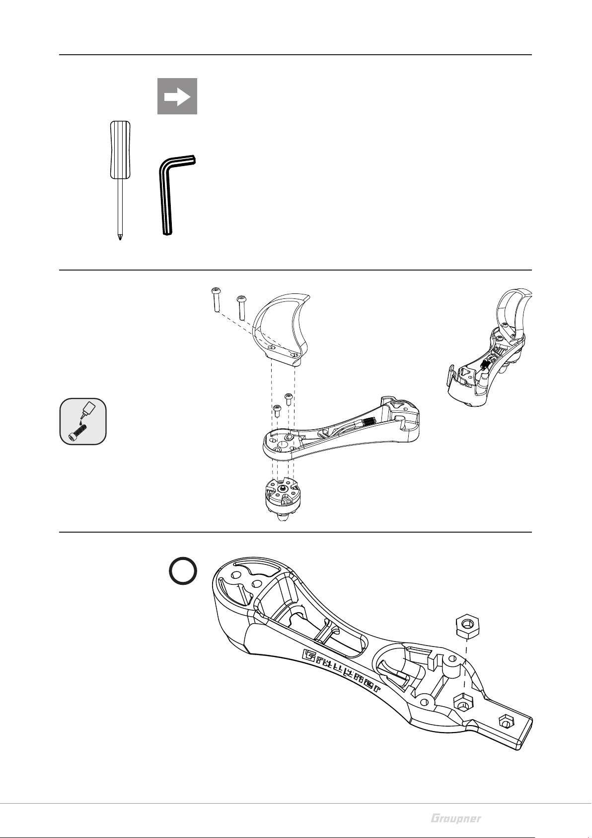
Required accessories
Allen key 1 and 1,5 mm
Phillips screwdriver 1,5 mm
Construction of the front arms
Construction of the back arm
1
Required parts
Front arms, left / right
2x skids, front
2x Motor S7049
4x Screws M3x8
4x Screws M3x14
Required parts
Rear arm
Nut M3

10 / 28 16540_jh_V1
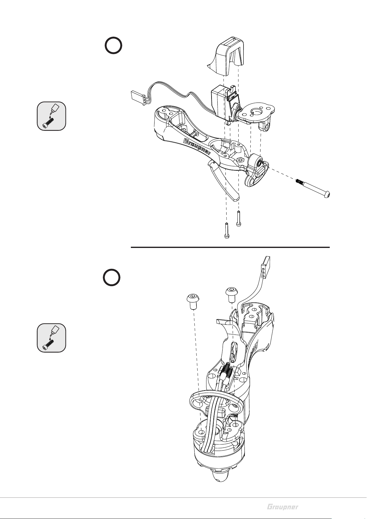
2
3
4
Required parts
Rear skid
1x Screw M3x8
Required parts
Lower motor holder
2x Ball bearings
Required parts
Servo
Upper motor holder
11 / 28
16540_jh_V1
5
6
Required parts
Servo holder
1x Screw M3x24
2x Screws M2x15
Required parts
1x Motor S7050
2x Screws M3x5

12 / 28 16540_jh_V1
Assembling the main chassis
Installing the upper chassis plate
Required parts
Lower left lateral part
Lower right lateral part
Main chassis plate
8x Screws M3x8
2x Spacer tubes
Required parts
Upper left lateral part
Upper right lateral part
Upper chassis plate
4x Screws M3x8
4x Nuts M3
13 / 28
16540_jh_V1
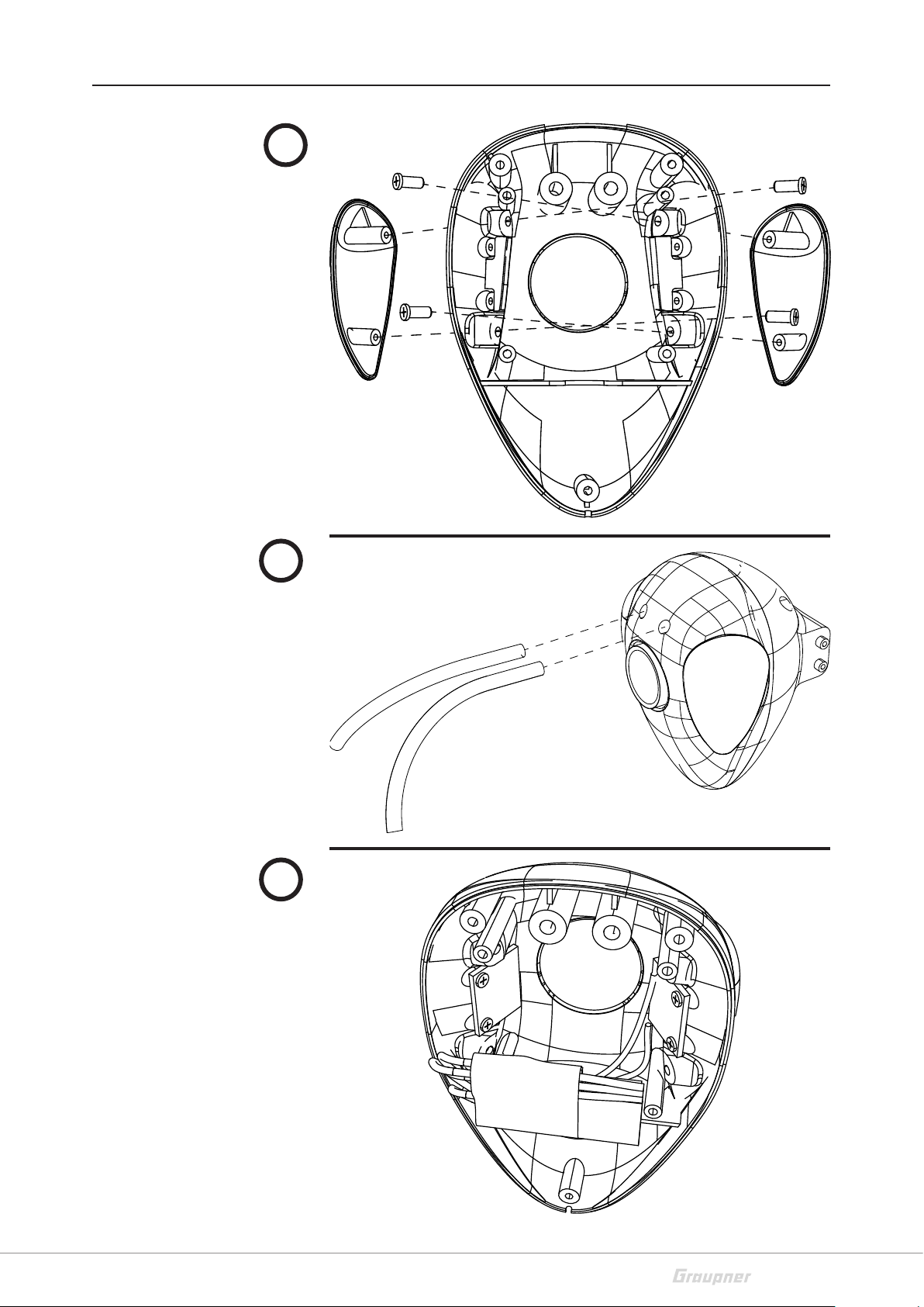
Assembly of the head
1
2
3
Required parts
Eye, left
Eye, right
4x M1,7x4
Required parts
2x Antenna tubes, curved
Required parts
LED
Glue pads

14 / 28 16540_jh_V1
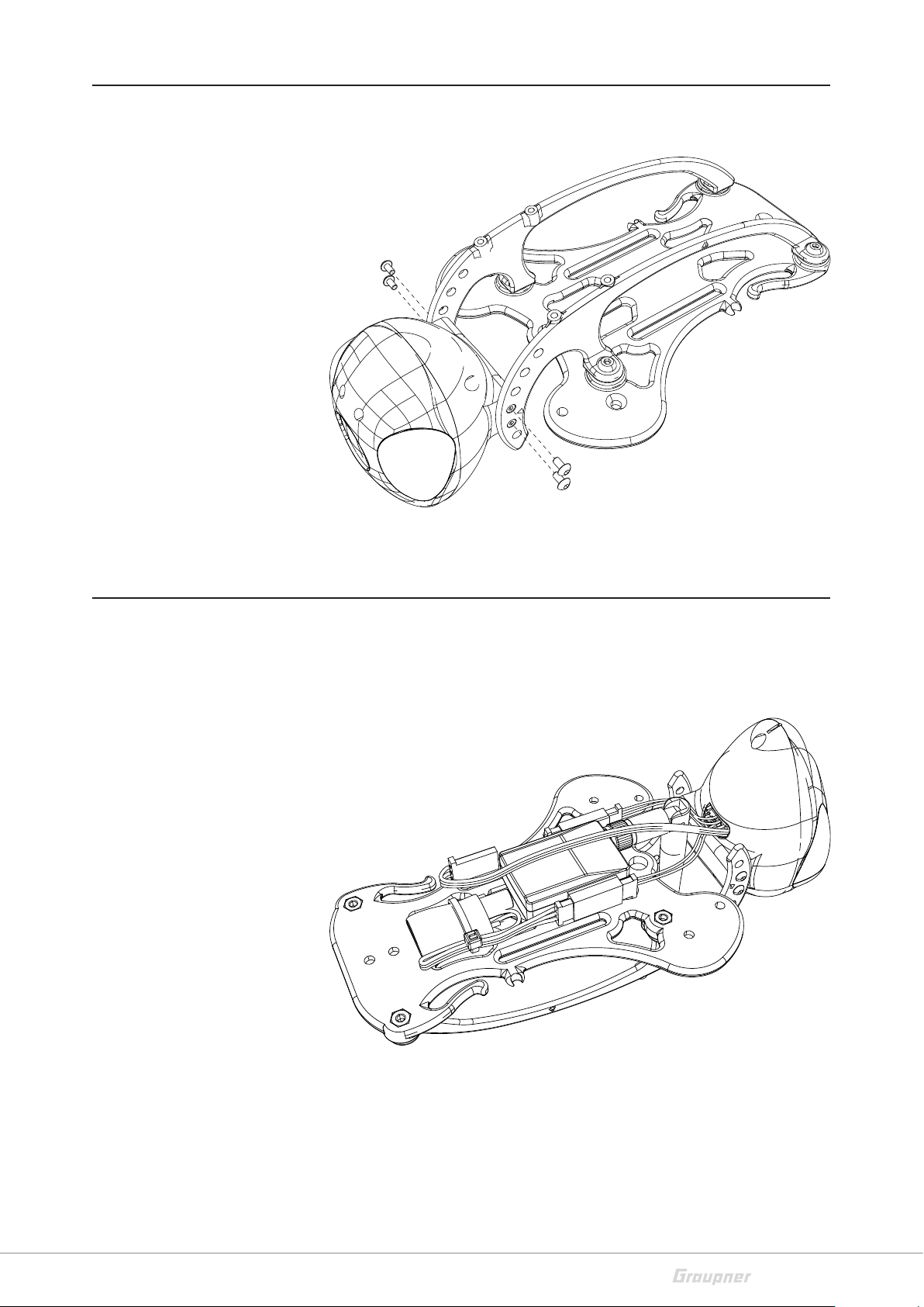
4
5
6
Required parts
4x M1,7x4
Required parts
3x M2x5
Required parts
LED module
Glue pads
15 / 28
16540_jh_V1
Installing the head
Installing the FPV transmitter with the camera BEC on the upper chassis plate
Required parts
4x Screws M2x4
Required parts
3x Cable ties
3x Glue pads
16 / 28 16540_jh_V1
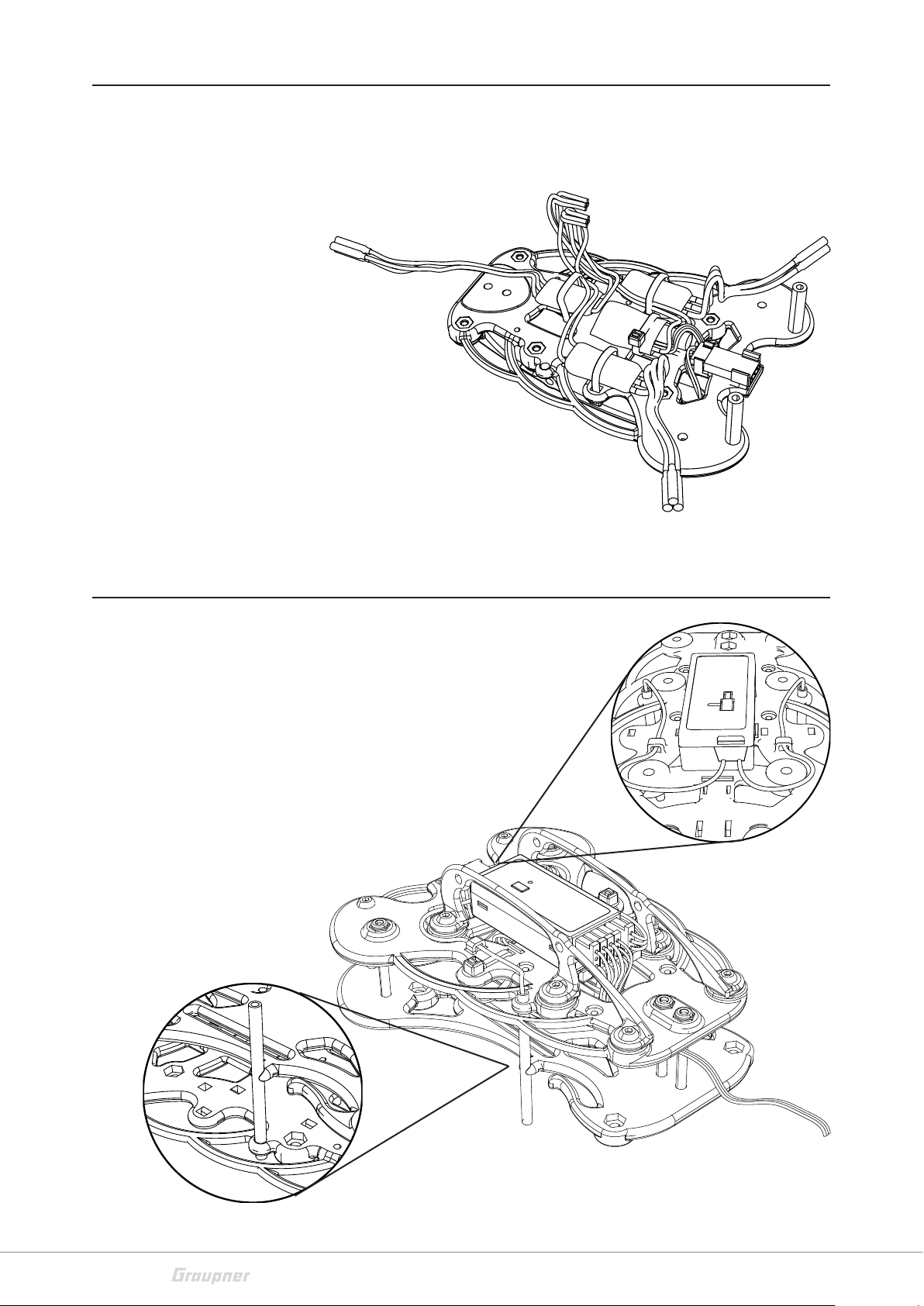
Installing the controller and the BEC
Installing the receiver
Required parts
3x Controllers
1x VM with SBEC
4x Glue pads
4x Cable ties
Required parts
1x Receiver
1x Glue pad
2x Antenna tubes

17 / 28
16540_jh_V1
Installing the arms on the main chassis plate
Required parts
4x Screws M3x30
2x Screws M3x8
4x Nuts M3

18 / 28 16540_jh_V1
Schematic diagram
1 Motor right
2 ESC right / channel 1
3 Camera BEC
4 Camera
5 Transmitter
6 Receiver
7VM+SBEC / Telemetry
8 ESC back / channel 3
9 Motor back
10 Servo / channel 4
11 Motor left
12 ESC left / channel 2
13 SXM module / channel 6
14 LED boards
Soldering the XT-60 connector
+
-
1.
2.
Required parts
XT-60 connector
2x Shrink tubes
12
3
4
5
6
7
89
10
11 12
13
14
Warning
Risk of injury by rotating propellers in case the motors start.
Install the propellers only after the following programming.
!

19 / 28
16540_jh_V1
Commissioning version 16540.CAM
To start fling you need the following items:
Transmitter HoTT (MX-12 / MZ-12 or higher)
LiPo battery 3S, Graupner LiPo battery V-MAXX 50 C 3/1500
mAh, No. 9717.3.D35
Video goggles or LCD monitor
Receiver
The transmitter is already completely set for HoTT Hornet. To pro-
gram some parameters, refer to the manual included with the
receiver.
Battery installation
Fix the battery with the included velcro tape and the fleece pad
into the battery case. Place the battery so that the tricopter’s
center of gravity is in the middle of the frame.
Commissioning version 16540 or 16540.C
These versions can be completed with different assembly parts,
pay attention to the use of the different parts in the manual.
We recommend the parts listed in the spare parts list because
they are specifically made for the tricopter.
Receiver’s binding
If you wish to bind the receiver to a new model memory, this is
the procedure:
Switch the transmitter’s RF section off in the “Basic model
settings” menu (see transmitter manual)
Switch on the receiver and put it in binding mode, by press-
ing and holding the binding button (green and red LED on
the receiver are flashing)
Initiate binding in the transmitter’s “Basic model settings”
menu.
If the red LED of the receiver goes out within about 10 sec-
onds and the green LED is illuminated, the binding process
has been completed successfully. Your transmitter/receiver
combination is now ready for operation.
If the red LED is still lit, the "binding“ failed. In this case,
repeat the whole procedure.

20 / 28 16540_jh_V1
Necessary pre-settings on the transmitter
In the transmitter it must be selected a free model memory, the
model type must be “surface model“ and the channel 1 direction
must be set so that in “motor off“ position the power indicator
must show -100%.
The flight mode must be set on channel 5. Then program a 2
way switch for channel 5 to control the flight mode:
Attitude mode: Channel 5 = -100% to +50%. The stick move-
ment influences the HoTT Hornet reaction on Roll and Nick. It
allows a maximal angle of about 50° at 100% of stick move-
ment. Mode suggested for beginners. The stick movements
acts directly proportionally to Roll and Nick.
Rate mode: Channel 5 = more than +50%. The stick movement
influences the rate without angle limit. Aerobatic mode that
allows rolls and loopings.
We suggest to set the fail-safe on channel 5 and channel 1 at
-100% , so that in fail safe it is active the attitude mode.
Program always the motors stop switch on the transmitter. (See
transmitter manual) This prevents accidental starting of motors,
thus reducing the risk of injury.
Initialization of the gyro in the receiver
Once the HoTT Hornet has been switched on, the gyro immedi-
ately becomes active but still needs to be initialized. To initialize
the gyro, keep your HoTT Hornet still when you switch it on. The
calibration process can only be performed when the receiver is
absolutely still. After 3 seconds in still position you will hear
beeps emitted by all motors.
These "wiggles" signal that initialization has been successful and
that calibration is complete. Always wait until the calibration pro-
cess has finished before starting to fly the model.
The motors will not start until the calibration is successfully
completed.
Auto-flip function version 16540.CAM
The auto-flip function allows you to flip your copter in a very easy
way. It is essential that you control in Attitude mode (function not
allowed in Rate mode). The auto-flip function is controlled by a
switch assigned to channel 6. (see manual S1019) Activate the
switch and within 5 sec move the nick or roll stick to more than
50% of its course, then the copter makes autonomously a flip in
the selected direction. After the flip it is possible to have some
little position movements (<10°)
Do not forget to set the failsafe up!
Program the motor stop switch!
Safety function - motors-off
Table of contents


