GAYLORD Ultima Vent GX2-UV User manual

THE
GAYLORD VENTILATOR
TECHNICAL MANUAL
FORTHE Ultima VentTM “GX2-UV” SERIES
NON WATER-WASH VENTILATORS
10900 S.W. AVERY STREET • TUALATIN, OREGON 97062-1149 U.S.A.
800-547-9696 • 503-691-2010 • FAX: 503-692-6048 • email: info@gaylordusa.com
GAYLORD INDUSTRIES
EFFECTIVE DATE 4-05

2
To Our Customers. . .
Congratulations on your recent purchase of a Gaylord
kitchen exhaust hood system. We are proud to be able
to provide you with a quality product that incorporates
the latest engineering concepts and is a result of over
50 years of experience in the foodservice kitchen
exhaust industry.
If you have other Gaylord equipment such as a Gaylord
UtilityDistributionSystem,QuencherFire ProtectionSys-
tem, or Roof Top Air Handling Equipment, etc., please
refer to the corresponding supplementary equipment
manuals.
If you have further questions, please call us toll free at
1-800-547-9696oremail:info@gaylordusa.com. Weare
more than happy to help.
Sincerely,
Gaylord Industries
STREET ADDRESS: 10900 S.W. Avery Street, Tualatin, Oregon 97062-8549 U.S.A.
PHONE: 503-691-2010 • 800-547-9696 • FAX: 503-692-6048 • email: ga[email protected] • www.gaylordusa.com
GAYLORD INDUSTRIES
World Headquarters: 10900 S.W.Avery Street •Tualatin, Oregon 97062-1149 U.S.A.
“Undisputed World Leader in
Engineered Systems for
Commercial Kitchens”tm
COMMERCIAL KITCHEN EXHAUST SYSTEMS • FIRE PROTECTION • UTILITY DISTRIBUTION • ROOF TOP UNITS • POLLUTION CONTROL

3
TABLE OF CONTENTS
“GX2-UV”VENTILATORMODELDESCRIPTION“ ..............................................................4
“GX2-UV” SERIES PRINCIPLE OF OPERATION .......................................................... 5 – 7
MAINTENANCEANDCLEANINGINSTRUCTIONS .............................................................8
UVPREVENTIVEMAINTENANCE .......................................................................................9
SAFETY CONCERNS WITH UV........................................................................................10
START-UP PROCEDURES .............................................................................................. 11
MEASURINGINLET SLOTVELOCITY ....................................................................... 12 –14
TROUBLESHOOTING ...............................................................................................15 – 20
MODEL CUV-100 SERIES CONTROL CABINET .............................................................21
MODEL CUV-100 SERIES CONTROL..............................................................................22
PARTS LIST ...................................................................................................................... 23
UV MODULE PARTS .........................................................................................................24
GEMSYSTEMDIAGRAM...................................................................................................25
UVHOOD WIRING ............................................................................................................26
WIRINGDIAGRAMS................................................................................................... 27 – 28
STANDARD VENTILATORMODELS.................................................................................29
METRICCONVERSION CHART .......................................................................................30
START-UP INSPECTION REPORT ..................................................................................31
WARRANTY ...............................................................................................Inside back cover
© Copyright 2005, Gaylord Industries
ADDITIONAL COPIES $10.00
Themanufacturerreservesthe right to modify thematerialsand
specificationsresultingfrom a continuing programofproduct im-
provement or the availability of new materials.
ALL RIGHTS RESERVED. NO PART OF THIS BOOK MAY BE REPRODUCED, STORED
IN A RETRIEVAL SYSTEM, OR TRANSMITTED IN ANY FORM BY AN ELECTRIC, ME-
CHANICAL,PHOTOCOPYING, RECORDINGMEANS OROTHERWISEWITHOUTPRIOR
WRITTEN PERMISSION OF GAYLORD INDUSTRIES COPYRIGHT 2004.
PATENT NUMBERS
U.S.A.: 4,266,529
4,281,635
4,356,870
CANADA: 1,139,151
1,155,366
GERMANY: 8,034,240

4
“GX2-UV” VENTILATOR MODEL DESCRIPTION
Thereare3differenttypesof“GX2-UV”“GrandGaylord”nonwater-washventilators.Thedifferences
involvethetypeandlocationoffiredamperandwhethertheventilatorhasafiredamper. Thefirstpart
ofthemodelnumber indicates the type of ventilator, see below:
Explanation of Prefixes:
GX2-UV-FDD Nonwater-washventilatorwithremovableextractorinsertsandafuselink
activatedfiredamperlocatedattheductcollar(
weighted
).
[NoDamper motor,No Thermostats]
GX2-UV-EDD Nonwater-washventilatorwithremovableextractorinsertsandathermo-
statically activated (
electric
) fire damper located at the duct collar. [
With Damper motor and 1 or more Thermostat(s)]
GX2-UV-ND Nonwater-washventilatorwithremovableextractorinsertsandNoFire
Damper.
[No damper motor, No Thermostats]

5
The Gaylord “GX2-UV” Series Non Water-Wash Ventilator
offers simplicity, economy and performance that no other
ventilator can offer. The unique “extractor insert” gives a
grease extraction efficiency far superior to that of a typical
bafflefilter.TheGaylord“GX2-UV”SeriesVentilatorsareUL
Listed and meet all the requirements of NFPA #96 and the
International Mechanical Code.
EXHAUSTFANOPERATION
TheexhaustfaniscontrolledbytheGaylordCUV-100Control
Cabinet. The cabinet is usually located on a wall near the
ventilator.Whenthecontrolisturnedon,theexhaustfanand
UV Lamps will come on.
GREASEEXTRACTION
TheGaylord“GX2-UV”SeriesVentilator extractsup to99%
of the grease, dust, and lint particles from the airstream
passing through it. Grease extraction is accomplished by
unique, removable stainless steel “extractor inserts” which
incorporate a series of horizontal baffles. As the air moves
through the extractor at high speed, it is forced to make a
seriesofturnsaroundthesebaffles,forcingtheheavier-than-
air particles of grease, dust, and lint to be thrown out of the
airstream by centrifugal force. The sticky grease collects in
the extractor and the liquified grease drains down into the
main grease gutter which slopes to the grease cup. Note:
“GX2-UV” SERIES PRINCIPLE OF OPERATION
Someventilatorsmaybeequippedwithoptional“CustomAir”
baffles (shown dotted) to reduce the exhaust volume over
specific light duty cooking appliances. The extractor inserts
come in two sizes15½" (5.6 lbs.) and 19½" (6.75 lbs.).
Particulate Separator
Once the largest particles of grease have been captured
throughinertialimpactionbythebaffles.Thesmallerparticles
ofgreasewillbearrestedintheparticulateseparatorusingthe
principlesofdiffusionandinertialimpaction.
UVLamps
Oncethebafflesandparticulateseparatorshavecollectedthe
grease particles larger than 1 micron. The UV lights will be
abletobreakdowntheremaininggreasebydirectexposure
to 254nm light and by the Ozone, Hydroxyl Radicals and
Anionicoxygencreatedbythe187nmUVlight.Thiswillcarry
down the ductwork and continue to break down the grease,
particulate and odor molecules keeping the ductwork much
cleaner.ThebyproductsofthisprocessareCO2,H20andthe
basemineralsfromthegreaseandparticulatemattercoming
offofthe cookingsurface.Therewillbealightgray dustthat
collects on the lamps, which will be need to wiped off. The
ductwork will need to be inspected per NFPA-96 schedules
but, will need much less frequent cleaning.
IMPORTANTNOTE:Neveroperateventilatorwithoutextrac-
tor inserts in place.
GREASE EXTRACTION
FIG. 1

6
“GX2-UV” SERIES PRINCIPLE OF OPERATION
FIG. 2
CLEANING
Atthe endof thecookingday theexhaust fanisturned offat
the CUV-100 control. After the fan has been turned off, the
extractorinsertsandparticulateseparatorsareremovedand
can be washed either in a dishwasher or soaked and rinsed
off.Thegreasecupisalsoremovedandemptiedatthistime.
Toeaseintheremovaloftheextractorinserts,an“Extractor
Removal Tool” is available which eliminates the need for
kitchen personnel to climb up on the cooking equipment, or
upa ladder.
TheUVlampswilldevelopacoatingofdust.Thiscoatingmust
beremovedforoptimumperformance.Therefore,onceaweek
whilethecartridgesareremoved,inspectthelampsandclean
asneeded.Useacleandryclothandifnecessarywashwith
milddetergentandwaterfirst.

7
“GX2-UV” SERIES PRINCIPLE OF OPERATION
FIREPROTECTION
NFPA-96 requires the use of Surface Fire Protection (Duct,
Plenum,Surface/Appliance)onallhoods.Itisthesesystems
that are the first line of defense against equipment fires.
The“GX2-UV-FDD”Seriesventilatorincorporatesafuselink
damper at the duct collar. In the event of a fire, should the
fuse link at the duct collar reach 280°F, the fuse link melts
allowing the damper to close. (See Fig. 3) After the fire is
extinguished the fuse link(s) in the duct collar needs to be
replacedandthedamperreset.
The“GX2-UV-EDD”SeriesventilatorincorporatesanElectric
Damper at the Duct collar and thermostat(s), which are
located at the point where the ductwork joins the ventilator.
FIG. 3
When the temperature of the conveying airstream, which
must pass over the thermostat(s), reaches 250°F, the
ElectricDamperattheDuctcollarclosesandtheExhaust
andSupplyfansandUVLampsshutoff,whentheventilator
andfansarewiredaccordingtoGaylord’swiringdiagram.
After the thermostat(s) cool below 250°F the damper will
resetautomatically, and theExhaust and Supplyfans will
restart,iftheCUV-100control is turned “ON”.
The“GX2-UV-ND”SeriesventilatordoesNOThaveadamper.
Thedamperinthe“GX2-UV-FDD”andthe“GX2-UV-EDD”
preventtheflamesfromenteringtheductworkandspread-
ingtootherpartsofthebuilding.Thefireiscontainedinthe
kitchenareawhere it can beproperlyfought.

8
MAINGREASE
GUTTER
DURING CLEAN-UP PROCEDURES AT
THE END OF THE COOKING PERIOD
SPECIAL ATTENTION SHOULD BE
GIVEN TO WIPING CLEAN THE AIR
INLET OF THE VENITLATOR
EXTRACTORINSERTS
DURING CLEAN-UP PROCEDURES
AT THE END OF THE COOKING
PERIODTHESE AREASSHOULD
NORMALLY BE WIPED DOWN.
CLEANING
At the end of each cooking day, the exposed interior
surfaces of the ventilator should be wiped down and the
greasecupemptied. Duringthecourseofoperation,grease
particlesaregraduallycollectinginsidetheextractorinserts
and particulate separator. Daily, or at periodic intervals,
dependingonthetypeofcooking,theextractorinsertsand
particulate separators, must be removed and cleaned. To
clean,proceedas follows:
1. Remove extractor inserts by hand or by using the
extractor removal tool. CAUTION: Care should be
takenwhenremovingextractors,especiallyoverfryers.
It is recommended that the cooking equipment be
cooleddownandthefryersbecoveredpriortoremoving
extractors. Toremove,liftupslightlyonextractorinsert
and pull straight out.
2. Extractor inserts may be cleaned either by using a
dishwasherorbywashinginasinkusinghotwaterand
a degreasing detergent. Formula G-510 is highly
recommended for this application. For information
contact:
20/10ProductsInc.
P.O. Box 7609
Salem,OR97303
Phone:800-286-2010
Fax:503-363-4296
E-mail:twentyte[email protected]
3. With the extractor inserts and particulate separators
removed,wipeandcleanthebackwallandthegrease
gutterwithhotdetergentwater. NOTE:Ifasteamorhot
waterpressurewasherisusedforperiodiccleaningof
theinterior,connectahosetothegutterdrainandlead
it to a floor sink or large bucket to drain off the water.
4. Toreplacetheextractorinserts, caremustbetakento
insure that point “A” rests in the rear clip as illustrated
in Fig. 4.
5. Iftheventilator(s)hasafuselinkoperatedsupplyduct
firedamperNFPA-96requiresinspectionofthefuselink
every6monthsandreplacementannually.
6. UVlampsmustbewipeddown
on a regular basis. This
may need to be done
asoftenasweekly
onsomesystems.
INSPECTION AND CLEANING REQUIREMENTS
The2001editionofNFPA-96(StandardforVentilationControl
and Fire Protection of Commercial Cooking Operations)
requirethathoods,ductsandexhaustfans beinspected by
aproperlytrained,qualifiedandcertifiedcompanyorperson(s)
inaccordance withthe followingtable.
Uponinspection,iffoundtobecontaminatedwithdepositsfrom
grease-laden vapors, the entire exhaust system shall be
cleanedbyaproperlytrained,qualified,andcertifiedcompany
orperson(s)acceptabletotheauthorityhavingjurisdiction.
Whenaventcleaningserviceisused,acertificateshowing
date of inspection or cleaning shall be maintained on the
premises. Aftercleaningiscompleted,thevent cleaning
contractor shall place or display within the kitchen area a
label indicating the date cleaned and the name of the
servicingcompany. Itshallalsoindicateareasnotcleaned.
Factory trained service agencies are certified by Gaylord
Industries,Inc.toperformtheseinspections.Forthename
andphonenumberofyournearestagentcall 800-547-9696
orwww.gaylordusa.comandgotoservice.
MAINTENANCE AND CLEANING INSTRUCTIONS
CAUTION: Care should be taken when removing extractors,
especially over fryers. It is recommended that the cooking
equipment be cooled down and the fryers be covered prior to
removing extractors.
FIG. 4
ELUDEHCSNOITCEPSNIMETSYSTSUAHXE
gnikooCfoemuloVroepyTycneuqerF
snoitarepognikoocemulov-hgihgnivressmetsyS gnikoockowrogniliorbrahc,gnikoocruoh-42sahcus ylretrauQ
gnikoocemulov-etaredomgnivressmetsyS snoitarepo yllaunnaimeS
hcus,snoitarepognikoocemulov-wolgnivressmetsyS ro,sessenisublanosaes,spmacyad,sehcruhcsa sretnecroines yllaunnA

9
UV PREVENTIVE MAINTENANCE
Theseitemswillneedtobeperformedbyatrainedandqualified
Certified Service Agency (CSA) on the same schedule as the
exhaustsysteminspection scheduledescribedin NFPA-96and
on the previous page in this tech manual. These tasks involve
potential exposure to high doses of UV light and live electrical
components.Thereisriskofinjurytoskinandeyesandinthecase
of electrical shock, injury or death! For a list of CSAs go to
www.gaylordusa.com and go to "Service Agencies" for a list of
companiesnearestyou.
1. Inspection of the Lamps and Ballasts
a. Checkthelampsforproperoperation
1. Turn on the fan and look for the green "UV System
On" light on each hood section
a. If it is not on refer to "UV Troubleshooting",
pages 17, 18 and 20.
2. Open the UV Access door with the key
3. Turnonfan
4. Verify all of the Extractor Inserts are installed.
5. Depress the UV Access door safety switch
6. Check all indicator LEDs, 6 green and 3 red, to
ensure that they are all on. If they are not all on go
to "UV Troubleshooting", pages 17, 18 and 20.
2. Inspect the Plenum (around the UV lamps)
a. DisconnecttheUV modulepower cord
b. RemovethenutsholdingtheUVmoduletotheventila-
torwitha nutdriver
c. RemovetheUVmodulefromtheventilator
d. Checkforbuild-upofdepositsofgrease,dustand/or lint.
e. Clean as necessary with a mild detergent, water and
arag
f. ReinstalltheUV module.
3. Test the Safety Interlock switches
a. RemoveoneExtractorInsertwiththefanon
• The UV lamps should shut off
• An audible alarm on the CUV-100 should come on
• TheRed“UVSafetyInterlockActivated”lightonthe
ventilator and CUV-100 control should come on
b. Open the UV Access door with the fan on
• The UV lamps should shut off
• An audible alarm on the CUV-100 should come on
• TheRed“UVSafetyInterlockActivated”lightonthe
ventilator and CUV-100 control should come on
c. Turn off the breaker to the Exhaust Fan. Press the
“StartFan” button on theCUV-100 control
• The UV lamps should shut off (stay off)
• An audible alarm on the CUV-100 should come on
• TheRed“UVSafetyInterlockActivated”lightonthe
ventilator and CUV-100 control should come on
4. Check all gaskets for damage
a. Replaceany gaskets that arewornor damaged
5. Check the Hour Meter
a. Recordthehours
b. Determinetheapproximatehoursbetweeninspection
intervals.
c. Determinewhenthe8000-hourlifeofthelampswill
occurandinformtheoperatoroftheapproximatedate
when the lamps will need to be replaced
Replacing UV Lamps
Danger!
Theseitemswillneedtobeperformedbyatrainedandqualified
CertifiedServiceAgency(CSA).Thesetasksinvolvepotential
exposure to high doses of UV light and live electrical compo-
nents.ThereisariskofseriousinjurytoskinandeyesfromUV
light.Thereisriskofshock,injury,and/ordeathfromelectrical.
For a list of CSA’s go to www.gaylordusa.com and go to the
“ServiceAgencies”foralistofcertifiedcompaniesnearestyou.
1. SecureallpowertotheCUV-100 control
2. Secure all circuits that provide power to the UV lamps
3. Open the UV Access door with the key
4. DisconnecttheUV modulepower cord
5. RemovethenutsholdingtheUVmoduletotheventilator
withanutdriver
6. RemovetheUVmodulefromtheventilator
7. Remove the bolts on each end of the UV module (2 on
each end) that hold the end caps on
8. Disconnect the lamp connector(s) on the UV lamp(s) to
bereplaced
• Eachlampconnectorshouldbelabeledfrom1to6on
bothends
• Lamp#1isattheFrontoftheventilatorwhentheUV
module is installed
• Lamp#6isattheBackoftheventilatorwhentheUV
module is installed
• Besuretore-labelthelampconnectorsifnecessary
9. Lubricatethelampsaroundthegrommetsoneachendofthe
UVlamp withasmallamountofG-510orsimilardetergent
10. Slide the UV lamp out one end, CAREFULLY!
11. Inspectthegrommets aroundthelamps
• Replace any grommets that show cracks, checking,
or any other damage
12. Checkallwires fordamage
• Replace any wires showing damage
13. Lubricate each of the new UV lamp(s) before installing
with a small amount of G-510 or similar detergent
14. Re-connectthelampconnectorsonbothendsof theUVlamps
• Eachlampconnectorshouldbelabeledfrom1to6)on
both ends
• Lamp #1 is at the Front of the ventilator when the UV
module is installed
• Lamp #6 is at the Back of the ventilator when the UV
module is installed
15. Re-install the UV module end caps and torque the bolts
to 7-10 in-lbs.
16. Re-installtheUVmodule in theventilator
17. Tighten all nuts holding the UV module to the ventilator
18. Re-connecttheUVmodulepowercord
19. CheckforproperoperationofUVlamps
Warning: DoNOTdefeatthepurposeoftheinterlocks duringcleaningand maintenance!
CERTIFIEDSERVICEAGENTMAINTENACEWARNING!

10
Aswithmanytypesoftechnologyifitisnotusedproperlyand/
orproper precautionsare nottaken thereis thepotential for
injury or harm. This is especially true with UVC light due to
thefactthatitdoesnotphysicallyhurtatthetimeofexposure.
While UVC is very effective at breaking down grease mol-
ecules, direct exposure to large amounts is harmful to skin
and eyes. The amount of UVC generated in these hoods is
greaterthanthatwhatresultsfromdirectexposuretothesun.
Under no circumstances is it acceptable to view the lighted
lamps without proper eye protection or expose bare skin
directly to the light. All interlocks and safety precautions
calledforinthismanualmustbefollowedtoavoidthepotential
for harm to service personnel and/or operators. In addition,
only trained and authorized personnel may perform some
maintenanceSeepreviouspagefordetails.
Personal Protective Equipment
1. Eyeprotectionthatprevents100%ofUVC beingtrans-
mitted through the lens must be worn at all times when
performing service work on any Ultima Vent that is
energized and/or has the potential to be energized and
expose personnel to UVC light.
2. Wheneverserviceworkisperformeditisrecommended
thatlongsleevepantsandshirtsbeworntominimizethe
potentialforinadvertentexposureoftheskin toUVC.
SafetyInterlocks
This product comes equipped with the following sensors to
verifythatallaccessdoorsareinplaceandthattheexhaust
fanisrunning:
1. MechanicaldoorswitchontheUVAccessdoortoensure
that the door is closed
2. GaylordExtractorMonitor(GEM) thatensuresall ofthe
Extractor Inserts are installed.
3. Air Pressure switch to verify air flow and exhaust fan
operation
Allofthesedevicesmustbeworkingand/oradjustedproperly
in order for the system to operate properly.
SAFETY CONCERNS WITH UVC

11
Beforeusing the Ultima Ventacomplete and thoroughstart-up ofthe Ultima Vent systemmustbe performed byaqualified, and
authorized service technician. Because of this the UV modules will be shipped separate from the hood to an Certified Service
Agent(CSA). Contact GaylordIndustries toarrange forthis service. It isnormally includedin thepurchase priceof thehoods.
8. Check the air velocity at the inlet slot
9. Record the data on the start up form. Determine the
correct inlet slot velocity and record that in the design
velocitylocation. Then determinethepercentage of de-
sign that the actual air velocity represents
11. RemoveanExtractorInsert
a. Thered“SafetyInterlock Activated”lampshouldcomeon
andan audible alarm sound.
12. Check the UV Access door interlock
a. Open the UV Access door with the fan on.The red
“SafetyInterlockActivated”lampshouldcomeon and
anaudiblealarmsound.
Caution:BeforeanyFiretestsareperformed,checkwith
the building superintendent to see if the Surface Fire
Protectionsystemiswiredtothebuildingalarm,monitor-
ingsystem, and/orfire department.
13. If the FP contractor is there have them trip the micro
switches on the FP system to verify that the Exhaust
Fan(s) starts and supply Fan(s) shut off.
14. Onceallisworkingcorrectlydemonstratethefollowingto
the end user
a. IfthehoodisinterlockedwiththeFPsystem.Havethe
FP contractor test it and confirm that the External fire
modeworksproperly.
b. InstructthemthatifforanyreasontheycanseetheUV
light directly they must shut off the hood immediately
and call a CSA.
c. Check for proper damper operation if this hood has a
damper
d. Howtoremove,cleanandreplacetheExtractorInserts
e. Thattheyneedtoperformtherequiredendusermain-
tenancedescribedin thetechmanualandhireCSAto
perform the UV maintenance as described in the tech
manualandhavetheductsysteminspected/orcleaned
pertherequirementsofNFPA-96.
f. Thefrequencywill need tobeadjusted based onthe
type,amountanddurationofcookingdoneatthissite.
q. Fill out the start up form completely with comments
r. NotifytheDealer/customeriftheairvolumesaremore
than 5% low or 10% high and give the dealer and GC
a copy of the Start-up report.
g. SendacopyoftheStart-upreporttoGaylordandkeep
a copy for your records.
START-UP PROCEDURES
Start-up requirements and activities
AtthetimeofshipmentaCertifiedServiceAgent(CSA)willbe
selectedtoperformtheinstallationoftheUVmodulesandthe
start-up for the Ultima Vent system.
TheServiceagentshouldconfirmthefollowingpriortogoing
to the job site:
1. The Exhaust and Supply fan(s) are connected to the
ductwork
2. Thefans have electricityandwill run
3. The CUV-100 control panel is mounted and has the
following:
a. PowertotheCUV-100
b. All necessary electrical connections between the CUV-
100 and the hood, surface fire protection system, and
fans.
4. All lighting wiring is connected to the hoods and light
switch
5. There is a 120 Volt, 20 Amp power circuit going to each
hood section, for UV lamps
6. Any personnel (Fire Marshal, owners rep., GC, FP
contractor,airbalancer,etc)requiredtowitnessthestart
upwouldneedtobenotifiedoftimeanddateforstart-up.
Field Start up directions
Allow about 1 hour per hood section, at the job site, for the
activitiesdescribedbelow:
1. CheckforpowertotheCUV-100andwiringbetweenthe
CUV-100andthehoods
2. Check that all Extractor Inserts are properly installed
3. StarttheexhaustfanbyturningtheCUV-100controlon.
Bothsupplyandexhaustfansshouldstart.Thegreen“UV
SystemOn”lightshouldbeon.Ifthisdoesnotoccurrefer
to"UV Troubleshooting"on pages17, 18 and 20.
4. TurnCUV-100controloff.Thiswillshutoff thefans.
5. Open the UV Access door and remove the blank plate
from the UV light opening.
6. InstalltheUVlightmodulesinthehood.Connecttheplug
on the UV module to the hood.
7. Start the exhaust fan and check for the green “UV
SystemOn”lightatthehood(s)andcontrolpanel.Make
sure that all access doors are closed.

12
MEASURINGINLETSLOTVELOCITY
Smoke capture and grease extraction efficiency are de-
pendentupontheproperairvelocityattheinletslotofthe
ventilator.Therequiredaverageslotvelocitiesareshown
on the “Air Velocity Chart” below. If the slot velocity is
below the required average, the exhaust fan must be
adjustedaccordingly.
NOTE: The height of the inlet slot can vary depending
uponthedesignoftheventilator. Itis,therefore,important
to first measure the inlet slot and compare it to the chart
below to determine the required average inlet slot veloc-
ity. The designed CFM per lineal foot is related to the
velocity as shown on the chart below. The total CFM for
the ventilator can be found on the ventilator nameplate.
(See Figure 6).
Airvelocityreadingslessthanwhatisspecifiedonthe“Air
Velocity Chart” may allow smoke and grease to escape
theconfinesoftheventilatorand/orreducegreaseextrac-
tion efficiency. This can result in grease deposits which
lead to sanitation problems or fire hazards if left uncor-
rected. If air velocity readings are higher than those
specified, it will require more energy to operate the
exhaustfanandexcessivenoiselevelswillresult. Higher
orlowervelocitiesthantherequiredaveragewillnormally
put the entire heating and ventilating system out of bal-
ance.Whenmeasuringtheairvelocityitisveryimportant
to take an average reading across the inlet slot plane as
described on Page 13. Positioning the sensing head
incorrectlywillgivevelocityreadingsthatcannotbecom-
pared to the “Air Velocity Chart”.
TRAHCYTICOLEVRIA
SEIRES"SD"TPECXESEIRES"2XG"LLAROF
lanimoN thgieH fo tolStelnI
motsuCtuohtiW selffaBriA motsuChtiW selffaBriA
dengiseD repMFC .tFlaeniL
telnIegarevA )MPF(yticoleVtolS
.niM mumitpO .xaM
dengiseD repMFC .tFlaeniL
telnIegarevA )MPF(yticoleVtolS
.niM mumitpO .xaM
"3 )dtS(
"4 )lnE(
052 072 582 003 004
0031 0631 5241 5641 0961
0831
5341
0051
5451
0871
0541 0051 5751 5261 0781
051 061 071 081 052
067 097 018 548 0401
008
038
558
088
5901
088 078 009 539 0511
MEASURING INLET SLOT VELOCITY
*SROTALITNEVSEIRES"SD"ROF
rePMFCdengiseD .tFlaeniL telnIegarevAderiuqeR )MPF(yticoleVtolS
latoT htoB stolS
tnorF tolS raeR tolS tolStnorF
.niM mumitpO .xaM
tolSraeR
.niM mumitpO .xaM
003 004 051 052 051 051 067 5731 008
0541 088 0251 595 595 526 526 556 556
13
MEASURING INLET SLOT VELOCITY
FIG. 5A
FIG. 5B
FIG. 5C
CROSS SECTION OF TYPICAL
VENTILATOR INLET SLOTS
Thestandard instrumentused for measuring the inletvelocities ona Gaylord
Ventilator is a Pacer, Model DA40 or DA4000 Digital Anemometer. This
instrument is the easiest, most accurate and the best suited for measuring
ventilator inlet slot velocities. To take accurate air velocity readings, follow
the instructions below.
Instructions
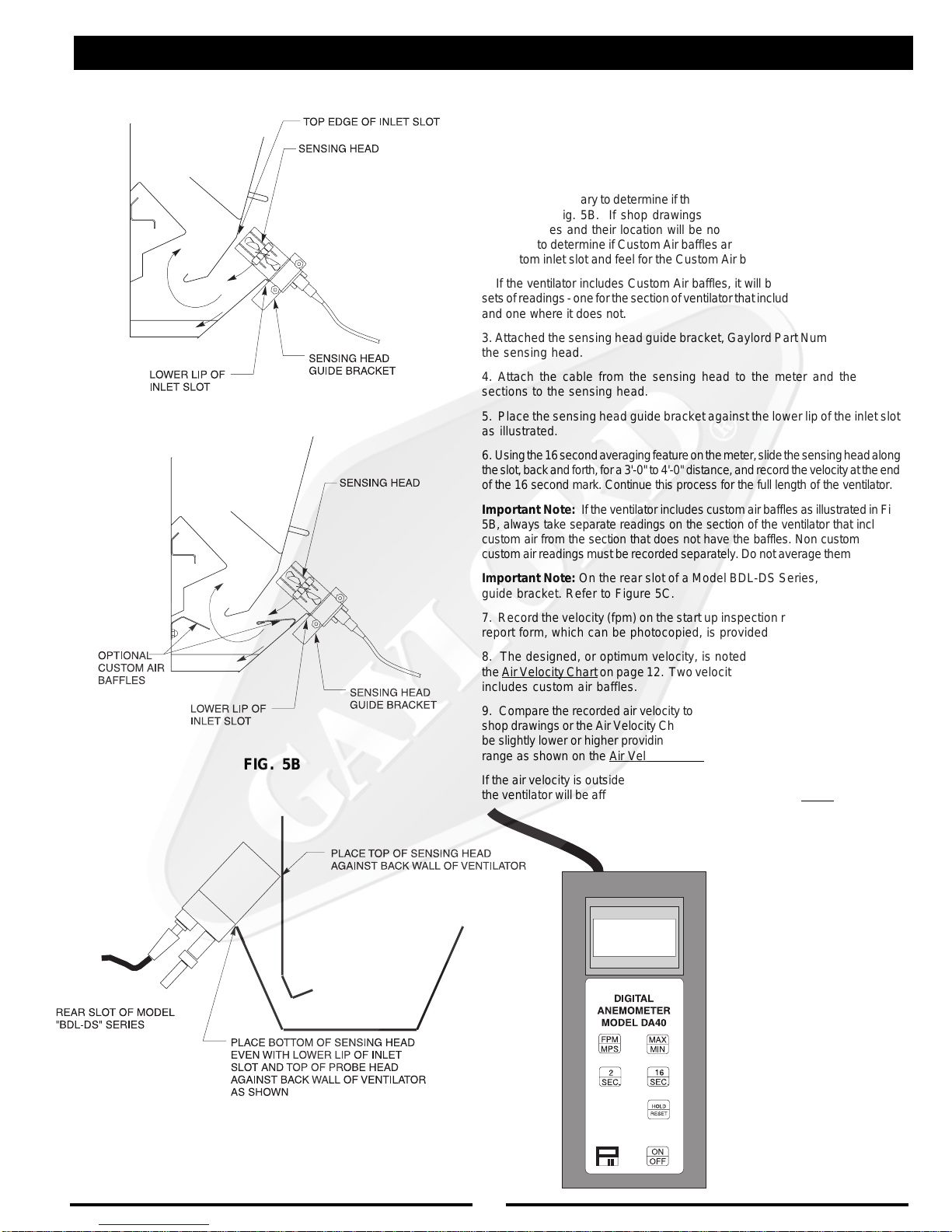
1. It is first necessary to determine ifthe ventilatorincludes CustomAir baffles
as shown in Fig. 5B. If shop drawings are available, and if equipped, the
custom baffles and their location will be noted on the front elevation. If not
available, to determine if Custom Air baffles are provided run your hand along
the bottom inlet slot and feel for the Custom Air baffle as illustrated in Fig. 5B.
2. If the ventilator includes Custom Air baffles, it will be necessary to take two
setsofreadings-oneforthesectionofventilatorthatincludesCustomAirbaffles
and one where it does not.
3. Attached the sensing head guide bracket, Gaylord Part Number 18408, to
the sensing head.
4. Attach the cable from the sensing head to the meter and the handle
sections to the sensing head.
5. Place the sensing head guide bracket against the lower lip of the inlet slot
as illustrated.
6. Usingthe16secondaveragingfeatureonthemeter,slidethesensingheadalong
theslot,backandforth,fora3'-0"to4'-0"distance,andrecordthevelocityattheend
of the 16 second mark. Continue this process for the full length of the ventilator.
Important Note: If theventilator includes custom air baffles as illustrated in Fig.
5B, always take separate readings on the section of the ventilator that includes
custom air from the section that does not have the baffles. Non custom air and
customair readingsmust berecorded separately. Do not average them together.
Important Note: On the rear slot of a Model BDL-DS Series, do not use the
guide bracket. Refer to Figure 5C.
7. Record the velocity (fpm) on the start up inspection report form. A sample
report form, which can be photocopied, is provided on page 16.
8. The designed, or optimum velocity, is noted on the shop drawings and
theAirVelocityChartonpage12. Twovelocitieswillbenotediftheventilator
includes custom air baffles.
9. Compare the recorded air velocity to the designed air velocity shown on the
shop drawings or the Air Velocity Chart on page 12. The recorded velocity may
be slightly lower or higher providing that it is within the minimum and maximum
range as shown on the Air Velocity Chart .
If the air velocity is outside the minimum/maximum range, the performance of
the ventilator will be affected and therefore the exhaust fan must be adjusted.

14
1. MINIMUM TOTAL EXHAUST
VOLUMEFOR THIS HOOD SECTION
2. MAXIMUMTOTALSUPPLY
VOLUMEFOR THIS HOOD SECTION
3. EXHAUSTSTATICPRESSUREAT
DUCT COLLAR
4. SUPPLYSTATICPRESSUREAT
DUCT COLLAR
5. THIS HOOD SECTION SUITABLE FOR APPLIANCES WITH MAXIMUM COOKING
SURFACETEMPERATUREOF:
˚F FOR LINEAL FT. OF HOOD
˚F FOR LINEAL FT. OF HOOD
6. REFER TO GAYLORD VENTILATOR TECHNICAL MANUAL FOR INLET
VELOCITYREQUIREMENTSANDMETHOD OF CHECKINGVELOCITY
7. ELECTRICAL RATING OF LIGHT FIXTURES: 120 VOLT, 60 HZ. OR 220 VOLT,
50HZ.OVERALL RATING -12AMPSOR LESS
8. ON "GX2" and "PG" SERIES VENTILATORS EQUIPPED WITH FUSE LINK
OPERATEDEXHAUST FIREDAMPER USEONLY 280˚ F,RATED 30LBS. MIN. UL
LISTEDFUSIBLELINKFORREPLACEMENT
9
. IF HOOD IS EQUIPPED WITH INTEGRAL MAKE-UP AIR WITH FUSE LINK OPER-
ATEDFIREDAMPER USEONLY165˚ F, RATED30LBS. MIN. ULLISTED FUSIBLE
LINKSFORREPLACEMENT
10.DUCTWORKANDEXHAUSTFAN
A. STATIC PRESSURE OF DUCT SYSTEM MUST BE ADDED TO VENTILATOR
STATICFORTOTAL SYSTEMSTATIC
B. ALL DUCTWORK MUST BE WELDED LIQUIDTIGHT
HOOD MOUNTING REQUIREMENTS
MINIMUM DISTANCE FROM COOKING SURFACE TO FRONT
LOWEREDGEOFHOOD
MAXIMUM DISTANCE FROM COOKING SURFACE TO FRONT
LOWEREDGEOFHOOD
MINIMUM OVERHANG FROM FRONT OF HOOD CAVITY TO
FRONT OF COOKING SURFACE
MAXIMUM SETBACK FROM FRONT OF HOOD CAVITY TO
FRONT OF COOKING SURFACE
MINIMUM OVERHANG FROM SIDE OF HOOD TO EDGE OF
COOKINGSURFACE
SERIAL NO:
MODEL NO:
W.G.
W.G.
ENGINEERING DATA
THIS EXHAUST HOOD HAS BEEN TESTED
TO STANDARD UL 710 "EXHAUST HOODS
FOR COMMERCIAL COOKING
EQUIPMENT"
THISEXHAUST HOOD IS LISTEDUNDER UL
FILE NUMBER 11403
THISEXHAUSTHOODMEETSALLREQUIRE-
MENTSOF THE LATESTEDITION OF NFPA-
96ANDTHEIMC(INTERNATIONALMECHANI-
CAL CODE)
oSUPPLIEDWITHFACTORY INSTALLED ULLISTED
GRINNELL CORP. EA-1, 1/4" ORIFICE, 65 DEGREE
DEFLECTOR SPRINKLER(S) FOR THE PROTEC-
TION OF UNLIMITED LENGTH OF GREASE DUCT
HAVING A MAXIMUM DUCT PERIMETER OF 50
INCHES PER SPRINKLER. CONNECT TO NFPA 13
SPRINKLERSYSTEMWATERSUPPLYONLY.
PATENT PENDING
EXHAUST HOOD WITH
EXHAUST DAMPER
UL-GX2/PG1000
WORLDHEADQUARTERS
GAYLORDINDUSTRIES,INC.
10900 S.W. AVERY STREET
TUALATIN, OR 97062-8549 USA
PHONE: 1-503-691-2010
FAX: 1-503-692-6048
LISTED
370Y
C.F.M.
C.F.M.
MAINTENANCE INSTRUCTIONS
1. REMOVE, INSPECT AND CLEAN FILTERS OR GAYLORD EXTRACTOR
CARTRIDGES AS REQUIRED
2. REMOVE AND EMPTY GREASE CUP AS REQUIRED
3. CAUTION-DONOTOPERATEVENTILATORWITHOUTFILTERSOREXTRACTOR
CARTRIDGESINPLACE
4. REPLACEFILTERSIN"PG"SERIESONLYWITHULCLASSIFIEDGREASEFILTERS.
IN "PGX" AND "GX2" SERIES REPLACE WITH GAYLORD INDUSTRIES
EXTRACTORCARTRIDGES.
5. IF THE VENTILATOR(S) HAS A FUSE LINK OPERATED EXHAUST OR SUPPLY
DUCT FIRE DAMPER THE NATIONAL FIRE PROTECTION ASSOCIATION'S
PAMPHLET NFPA-96 REQUIRES INSPECTION OF THE FUSE LINK EVERY 6
MONTHS AND REPLACED ANNUALLY. REFER TO THE GAYLORD VENTILATOR
TECHNICALMANUAL FORDETAILS.
The total required exhaust volume can be
found stamped on the UL nameplate located
on each hood section.
FIGURE 6
MEASURING INLET SLOT VELOCITY
TOTAL EXHAUST CFM HERE
TOTAL SUPPLY CFM HERE

15
TROUBLE-SHOOTING
MOTPMYSMELBORPELBISSOPNOITCAEVITCERROC
SSOLEKOMS
.1tonsirotalitneV-ssoLekomS .ylreporpgnitsuahxe .A
.B
.C
.D
.E
yticolevriaegarevA-yticolevriawoL niebdluohstolsyrtneriaehthguorht notrahCyticoleVriAehthtiwecnadrocca gnirusaemfodohtemreporproF.21egap ehtfI.31egapotrefer,yticolevriaeht .gniwollofehtkcehcwolsiyticolev
nwostievahtsumrotalitneVdrolyaGehT hcus,tsuahxerehtoondnametsystsuahxe .tiotnideitebdluohs,sdoohrehsawhsidsa
.sresuffidriapu-ekamdecalpylreporpmI
.riapu-ekametauqedanI
.egrahcsidnaftsuahxE
.1
.2
.3
.4
.5
.1
.1
.2
.3
.1
.2
.1
.2
.naftsuahxeehtnotlebgnippilsronekorB
.leehwnaftsuahxeehtfonoitatorreporP
reviledtsumnaf(naftsuahxefoezisreporP .)gnitaretalpeman
.nepotfellenapnoitcepsnikrowtcuD
.noitisopreporpnironepotonrepmaD
erehttahtyfirevdnametsystcudtcepsnI epytoneraIIfI.nideitsmetsysrotalitnev .devomerebtsumyehtos
lliwrotalitnevehttadetceridriapu-ekaM riaehtgnitpursidstfardssorcetaercylekil srevuolehttsujdA.rotalitnevehtotniwolf ehtmorfyawariapu-ekamehttceridot .rotalitnev
hguorhtdereviledebdluohsriapu-ekaM sretsigerrosresuffiddetarofrephtgnellluf ehttuohguorhtdetubirtsidthgiehgniliecta .aeranehctik
ehtraendetacolsretsigerriapu-ekaM otdetsujdaebdluohssrevuoleht,rotalitnev .rotalitnevehtmorfyawariaehttcerid ehttariapu-ekamgnicrofrognitceriD stfardssorcsetaercyllacipytrotalitnev .ssolekomsnignitluser
rofdeilppusebtsumriapu-ekaM llahguorhtdetsuahxeriafotnemecalper .smetsystsuahxenehctik
ot%57tahtsi"bmuhtfoelur"larenegA ,hserfebdluohsriatnemecalperehtfo%08 thguorbria)deloocrodetaeh(,denoitidnoc gniniamerehthtiw,aeranehctikehtotni nehctikehtotniwolfotdewolla%52ot%02 .saeratnecajdamorf
ehtrevoneercsonebdluohserehT ebdluohsti,dnuofsienofI.egrahcsid .devomer
ebtondluohsegrahcsidfonoitceridehT drawnwodronsdniwgniliaverpehtotni ylhgihsiegrahcsidlacitrevA.foorehtotno .dednemmocer
NOITCARTXEESAERG
.1.noitcartxEesaerGrooP.ArotalitneVseireS"VU-2XG"drolyaGehT dnatsud,esaergehtfo%99otpustcartxe gnissapmaertsriaehtmorfselcitraptnil deniatniamdnadetareponehw,tihguorht fI.snoitacificepsngisedhtiwecnadroccani tonsirotalitnevehttahtsraeppati tsuahxeehtyllacipyt,ylreporpgnitcartxe .wolsiemulov
.1nodebircsedsayticolevtolstelniehtkcehC tonsiyticolevehtfI.31hguorht21segap roesaercni,egnarderiuqerehtnihtiw .deriuqersadeepsnafehtecuder

16
TROUBLE-SHOOTING
MOTPMYSMELBORPELBISSOPNOITCAEVITCERROC
NAFTSUAHXE
.1ehtnodenrutsihctiwsnafehtnehwfI
.noemoctonseodnaftsuahxe
.A
.B
.C
.D
retratscitengamnorotcetorpdaolrevO
.deppirt
Iepyt)citamotuA/nOsdnaH(AOHnaf
eht,desusihctiwsretratscitengam
devomneebevahyamhctiwsrotceles
noitisopcitamotuaehtmorf
.deppirtrekaerbtiucricnaftsuahxE
nahtiwdeppiuqesimetsysehtfI
,naftsuahxeehtrofhctiwstcennocsid
.tuonwolbevahyamsesufroesufa
.1
.1
.1
.1
ehtnonottub"teseR"ehthsuP
hsupehtdnaretratscitengam
ehtnonottub"naFtratS"eht
.retnecdnammoc
otrotcelesnrutdnahctiwskcehC
.noitisopcitamotuaeht
rekaerbtiucrictes-eR
dnasesuffoytiunitnockcehC
.yrassecenfiecalper

17
Danger!
Theseitemswillneedtobeperformedbyatrained,qualified
and Certified Service Agency (CSA). These tasks involve
potentialexposuretoUVlightandliveelectricalcomponents.
TROUBLESHOOTING UV SYSTEM
There is risk of injury to skin and eyes and in the case of
electrical shock, injury or death! For a list of CSA’s Go to
www.gaylordusa.comandgotoService fora listofcompa-
nies nearest you.
1. After CUV-100 is turned on, fan starts:
* Yellow "UV Lamp Failure" light is on
* Audible Alarm is on
A. No power to the ventilator section(s). 1. Check for 120 Volts on between L1 & L2 at
ventilator. If there is no power at L1 and L2
coming to this ventilator section identify the
circuit breaker, correct and re-check.
B. Loose wire between CUV-100 and
ventilator. 1. Check for 120 Volts between 6U and 5U in
the ventilator. If none check CR13 in the
CUV-100 for power and operation. If there
is power there check for 120 volts between
1U and 5U. If there is power, check the
green lamps for proper operation.
C. No start signal from CUV-100 to ventilator
section(s). 1. Check Fuse F7 in CUV-100.
D. Fuse is blown on UV Controller in ventilator. 1. Check Fuse F2 on the UV Controller.
E. The contactor has failed (CR20). 1. If there is power to L1 and L2. Check for
power to the contactor coil (CR20). Correct
lack of power.
F. Green "UV System On" light has failed. 1. Check for power to the Green "UV System
On" light
a. If no power, Check the circuit and
locate problem.
b. If there is power the Green "UV
System On" light has failed and needs
to be replaced.
2. * Yellow "UV Lamp Failure" light is on
* Green "UV System On" light is on A. UV Lamp or UV Ballast has failed. 1. Identify ventilator section with Yellow “UV
Lamp Failure” light on.
* Audible Alarm is on 2. With fan running, Open UV Access door
3. Depress the UV Access door switch and
identify which Lamp/Ballast’s green light is
not on
4. Switch the pin connector on that Ballast with
another Ballast and check again
a. If the alternate Ballast’s green light
comes on, replace the Ballast
b. If the alternate Ballast’s green light
does not come on, replace the Lamp
B. The contacts on the UV Controller have
closed permanently. 1. Check for continuity between 2A and 3A in
ventilator. If there is continuity AND all of
the UV lamps are working, (6) green and
(3) red lights on at the UV Controller, the UV
Controller needs to be replaced.
C. Relay CR22 in ventilator has failed. 1. With Exhaust fan on, check for continuity
across the N.O. contacts of CR22 in the
ventilator. If there is continuity AND all of
the UV lamps are working, replace relay
CR22.
D. Relay CR12 in CUV-100 has failed. 1. Check CR12 for proper operation, replace if
necessary.
3. Yellow "UV Lamp Failure" light is on
ONLY at CUV-100 control NOT on any of
the ventilator sections.
A. Yellow "UV Lamp Failure" light on ventilator
has failed. 1. Check the Yellow "UV Lamp Failure" light
and see if it is receiving power.
a. If no, the problem is in the wiring.
Locate and correct the problem
b. If yes, replace the lamp.
SYMPTOM POSSIBLE PROBLEM CORRECTIVE ACTION

18
TROUBLESHOOTING UV SYSTEM
4. During the lamp inspection one of the UV
Controllers does not have (6) Green & (3)
Red indicator lights on and there is no
Yellow "UV Lamp Failure” lamp on.
A. The Yellow "UV Lamp Failure" light has
failed. 1. Check the Yellow "UV Lamp Failure" light and
see if it is receiving power.
a. If no, the problem is in the wiring.
Locate and correct the problem
b. If yes, replace the lamp.
2. If the Yellow "UV Lamp Failure" light has power,
replace the light.
B. The Connection from the 2A on the UV
Controller and the terminal blocks is broken
or loose.
1. It may be the contacts on the ballast
a. Check for power coming out of
terminal 2A in the ventilator
C. The contacts on the UV Controller has failed
to close. 1. Check for continuity between 2A and 3A at
ventilator. If a UV lamp has failed and there are
(6) green and (3) red lights on on the UV
Controller, the UV Controller needs to be
replaced.
5. Red “UV Safety Interlock Activated” light
on AND Audible Alarm on. A. UV Access Door Switch (DS) has failed or
needs to adjusted. 1. Check for continuity between D1 & D2 and D3 &
D4 with the door switches depressed. If there is
2. If there is continuity check the UV Pressure
Switch and UV Proximity Switch.
B. An Extractor Insert has been removed or is
not properly inserted 1 Remove and re-insert Extractor Insert
C. Gaylord Extractor Monitor (GEM) has failed 1. Check for continuity between G1 and G2.
D. Pressure switch (PS) has failed or needs
adjusting. 1. Check for power to the UV Pressure Switch with
the fan on.
2. Check for continuity between P1 and P2. It
should be closed with the fan on
3. With the fan on turn the pressure switch
adjustment screw Clockwise until there is
continuity between P1 and P2.
4. If there is continuity, check the UV Access Door
Switch and the UV Proximity Switch
D. Pilot tube to sense air pressure is plugged. 1. Check the Pitot tube for blockage. Clear and
check again.
2. Check all tubing connections to make sure they
are tight.
E. Relay CR23 in ventilator has failed. 1. With Exhaust fan on, close Inspection (wash
access) doors and depress UV Access Door
switches. Check for continuity across the N.O.
contacts of CR23 in the ventilator. If there is
continuity, replace relay CR23.
F. Relay CR11 in CUV-100 has failed. 1. Check CR11 for proper operation, replace if
necessary.
6. Pressing "Cancel Audible Alarm" button
on CUV-100 does NOT silence alarm. A. Timing Relay TR1 in CUV-100 is not set
correctly or has failed. 1. Check TR1 for proper operation and verify it is
set for 1 second.
B. Relay CR10 in CUV-100 has failed. 1. Check Yellow “UV Lamp Failure” lights. Identify
which ventilator section(s) has the same light
on. If it is on, see above for solution.
7. Audible alarm comes on for
approximately 60 Seconds each day
when "Start Fan" button is pressed.
A. Timing Relay TR2 in CUV-100 is not set
correctly or has failed. 1. Check TR2 for proper operation and verify it is
set for 60 seconds.
SYMPTOM POSSIBLE PROBLEM CORRECTIVE ACTION

19
CUV-100 TERMINAL VOLTAGES
TROUBLESHOOTING UV SYSTEM
TROUBLESHOOTING
TERMINAL DESCRIPTION FAN OFF FAN ON EXT. FIRE
L1 Main Power Connection : Hot 120 VAC 120 VAC 120 VAC
L2 Main Power Connection : Neutral
1 Output to Supply Fan Motor Starter 0 VAC 120 VAC 0 VAC
5 120 VAC Neutral Leg
8 Output to Exhaust Fan Motor Starter 0 VAC 120 VAC 120 VAC
FS1
FS2 Supply Fan Fire Switch Connections
N.C. Contacts Closed Closed Open
FS3
FS4 Exhaust Fan Fire Switch Connections
N.O. Contacts Open Open Closed
1U Input from "UV System On" (Green) 0 VAC * *
2U Input from "UV Lamp Failure" (Amber) 0 VAC * *
3U Input from "UV Safety Interlock Activated"
(Red) 0 VAC * *
5U 120 VAC Neutral Leg
6U Output to UV Lamps Contactor 0 VAC 120 VAC 120 VAC
120 VAC - when UV lights should be on
0 VAC - when UV lights should be off
(Refer to UV Status Light Chart on following page)
High Voltage Common
High Voltage Common
Common

20
TROUBLESHOOTING
UV Controller Status Lights
Normal Operation
• 3 Red lights on
• 6 Green lights on
UV Lamp Failure
• "Summary Alarm" light is OFF
• TheGreenlightfortheUVLamp/Ballast
that has failed will be OFF
NOTE:
• UV Lamps are numbered 1 to 6 from
Front-to-Back
• UV Ballasts are numbered 1 to 6 from
Left-to-Right
• TheTOPoftheUVModulehasseveral
longslotscut-outforventilation
UV Status Lights
UV System Mode Green
"UV System On"
light on
Yellow
"UV Lamp Failure"
light on
Red
"UV Safety Interlock
Activated"
light on
All UV Lamps ON "Normal" X
One or more UV Lamps
not working XX
UV Module un-plugged XX
No power to the UV Module
(All Doors closed) X
UV Access Door Open X
Inspection (Wash Access) Door
Open X
Exhaust Fan is not running at full
speed X
"UV System On" (Green) Light
"UV Lamp Failure" (Yellow) Light
"UV Safety Interlock Activated" (Red) Light
* ON when a UV Access Door is open
* ON when a Inspection (Wash Access) Door is open
* ON when UV Pressure Switch detects that the static pressure is too low
* All UV Lamps will shut off immediately, whenever any of the above happens
UV Status Li
g
hts
The UV System is designed to run whenever the Exhaust Fan is running.
* ON when UV System is energized
* ON whenever UV System is energized and one or more of the UV Lamps and/or UV
Ballasts have failed or if the UV Lamps do not have power
* The rest of the UV Lamps will continue to run - call a Certified Service Agent for service
The UV Status Lights will only activate when the UV System should be on. (Exhaust Fan Running)
Table of contents
Other GAYLORD Fan manuals


Popular Fan manuals by other brands

colt
colt CYCLONE installation manual

colt
colt AXS 140 Installation, operation and maintenance manual

Sunshine Solar
Sunshine Solar SSS224G installation guide

Vortice
Vortice VORT QUADRO manual

Home Decorators Collection
Home Decorators Collection KENSGROVE YG493ODC-MBK Use and care guide

Vents-us
Vents-us VKM 100 E user manual


