GAYLORD ELXC Series User manual

10900 S.W. AVERY STREET • TUALATIN, OREGON 97062 U.S.A.
GAYLORD INDUSTRIES
EFFECTIVE DATE 06-2011
OPERATION, MAINTENANCE
& INSTALLATION MANUAL
For
“ELXC” AND “ELXC-UV” SERIES
VENTILATORS
Rev. 07
10900 S.W. AVERY STREET - TUALATIN, OREGON 97062 U.S.A.
email: info@gaylordventilation.com - 800-547-9696 - FAX: 503-692-6048
www.gaylordventilation.com
OPERATION, MAINTENANCE
& INSTALLATION MANUAL
For
“ELXC” AND “ELXC-UVi” SERIES
VENTILATORS

ii
ALL RIGHTS RESERVED. NO PART OF THIS BOOK MAY BE REPRODUCED, STORED IN A
RETRIEVAL SYSTEM, OR TRANSMITTED IN ANY FORM BY AN ELECTRIC, MECHANICAL,
PHOTOCOPYING, RECORDING MEANS OR OTHERWISE WITHOUT PRIOR WRITTEN
PERMISSION OF GAYLORD INDUSTRIES. COPYRIGHT 2011.
© Copyright 2011, Gaylord Industries
The manufacturer reserves the right to modify the materials and
specicaons resulng from a connuing program of product
improvement or the availability of new materials.
ADDITIONAL COPIES $25.00

iii
Gaylord Industries
10900 SW Avery St.
Tualatin, OR 97062
Office: 503.691.2010
Toll Free: 800.547.9696
www.gaylordventilation.com
Gaylord Industries 10900 SW Avery Street Tualatin, OR 97062 www.gaylordventilation.com
To Our Customers:
Congratulations on your recent purchase of an ELXC or ELXC-UVi Series Ventilator. We are proud to be
able to provide you with a quality product that exemplifies our long standing dedication to quality
engineering and manufacturing.
Your ELXC or ELXC-UVi Series Ventilator is assembled from some to the very finest components
available and is designed for years of efficient, effective, and trouble-free operation. In addition, the
product has undergone rigorous quality control inspections and testing prior to shipment.
If you have any questions, please contact us at info@gaylordventilation.com or by calling us toll free
800-547-9696. We are more than happy to help.
Sincerely,
Gaylord Industries

iv
Table of Contents
Chapter 1 – Introducon Page
Introducon ..……………………………………………………………………………………………………………………. 1-1
Model Descripon …………………………………………………………………………………………………………….. 1-2
Model Number Sequence ………………………………………………………………………………………………. 1-3
Chapter 2 – Principles of Operaon
ELXC Series - Turning on the Exhaust Fan .............................................................................. 2-1
ELXC Series - Turning o the Exhaust Fan ………………….………………………………………………………… 2-3
ELXC Series - Wash Cycle ………………………………………………………………………………………………..…… 2-3
ELXC Series - Fire Protecon ……………………………………………………………………………………………..… 2-5
ELXC-UVi Series - Turning On the Exhaust Fan and UV System …............................................. 2-7
ELXC-UVi Series - Turning O the Exhaust Fan and UV System .……………………………………………. 2-10
ELXC-UVi Series - Wash Cycle .................…………………………………………………………………………….. 2-11
ELXC-UVi Series - Fire Protecon ………………………………………………………………………………………… 2-13
Wash System Overview ........................……………………………………………………………………………… 2-15
Wash System - Frequency and Length of Wash ................…………………………………………………… 2-15
Wash System - Recommended Detergent …………………………………………………………………………… 2-17
Balancer Dampers ...............………………………………………………………………………………………………. 2-19
Chapter 3 - Maintenance
Operator Preventave Maintenance ...................……………................................................... 3-1
UV System - Scheduled Prevenve Maintenance …………………………………………………………….... 3-3
Chapter 4 - Troubleshoong
Trouble Shoong ……………………………………………………………………………………………………………… 4-1
Venlator Control Matrix .………………………………………………………………………………………………… 4-5
Chapter 5 – Tesng and Repair
Measuring Airow .............................................................................................................. 5-1
Makeup Air Guidelines ……………….……………………………………………………………………………………. 5-6
Replacing UV Lamps ........................................................................................................... 5-7
Replacing UV Lamp Sockets ................................................................................................ 5-10
UV Ballast Box – Overview ................................................................................................. 5-14
UV Ballast Box – Replacing Parts ........................................................................................ 5-15
UV Ballast Box – Seng Pressure Switches ......................................................................... 5-16
Venlator Water Solenoid Valves ........................................................................................ 5-23
Venlator Spray Nozzles ..................................................................................................... 5-25
Chapter 6 - Parts
Parts - Venlator ..................................................................................................................... 6-1
Parts – UV Venlator …………………………………………………………………………………………………………. 6-4
Parts – UV Lamp Module …………………………………………………………………………………………………… 6-5
Parts – UV Ballast Box ……………………………………………………………………………………………………….. 6-7
Chapter 7 – Wiring Diagrams
Wiring Diagrams ……………………………………………………………………………………………………………….. 7-1
Appendices
Installaon Requirements …………………………………………………………………………………………………. A-1
Typical Installaon Illustraon .…………………………………………………………………………………………. A-5
Venlator Start-Up Inspecon and Tests - Overview..……………………………………………………...... B-1
Pre-Start-Up Checklist ..............................................……………………………………………………...... B-1
Start-Up Inspecon and Test Report Forms ..............……………………………………………………...... B-3
Limited Warranty .........................……………………………………………………................. Inside Back Cover

1-1
Chapter 1 - Introducon
Introducon
About this Technical Manual
The purpose of this manual is to provide the Operator, Maintenance and Service personnel instrucons for
operang, maintaining and troubleshoong the Gaylord Venlator. Venlators incorporang UV Systems,
most maintenance and all repairs must be performed by a trained and cered service company. This man-
ual also includes informaon and guidance to contractors for inial installaon of the Venlator.
The manual is divided into chapters for easy reference to a parcular subject. The pages in the chapters
are numbered with the chapter number, then a dash, and then the page number. So for example pages in
Chapter 2 are numbered 2-1, 2-2, 2-3 etc. Figures and Tables are numbered in a similar manor. For example
Figure 5-3-2 is on page 5-3 and is the second gure. Please keep your manual in a convenient locaon so it
can be accessed easily.
If you have any quesons or concerns with the installaon, operaon, maintenance or service of your Gay-
lord Venlator, please contact Gaylord Industries;
Web: www.gaylordvenlaon.com
E-Mail: info@gaylordvenlaon.com
Main Phone: 503-691-2010 Toll Free: 800-547-9696
Safety
It is important that the operator read Chapter 2, Principle of Operaon, and Chapter 3, Maintenance, before
operang the Venlator for the rst me. Parcular aenon should be given to all the Cauon and Warn-
ing statements.
Related Technical Manuals
1. ELXC and ELXC-UVi Series Venlators are controlled by a Gaylord Command Center. The specic
manual for this control is tled Operaon and Maintenance Manual for the Gaylord Command
Center.
2. ELX and ELX-UVi Venlators may include a Gaylord “Capture Wall” opon. The specic manual for
installaon of this is tled Installaon Manual – ELX Venlators with Capture Wall.
Operaon and Maintenance Manuals may be downloaded from the Gaylord website:
www.gaylordvenlaon.com or be obtained by calling Gaylord Industries.
1-2
Chapter 1 - Introducon
Model Descripon Overview
The Gaylord Model ELXC Series Venlator is a high grease extracon eciency Venlator that incorporates
a hot water Wash Cycle that automacally washes the accumulated grease out of the Venlator and into
the building drain system. The Model ELXC-UVi Series includes the addional feature of an Ultraviolet Light
System that dramacally reduces grease accumulaon in the exhaust plenum, ductwork and fans.
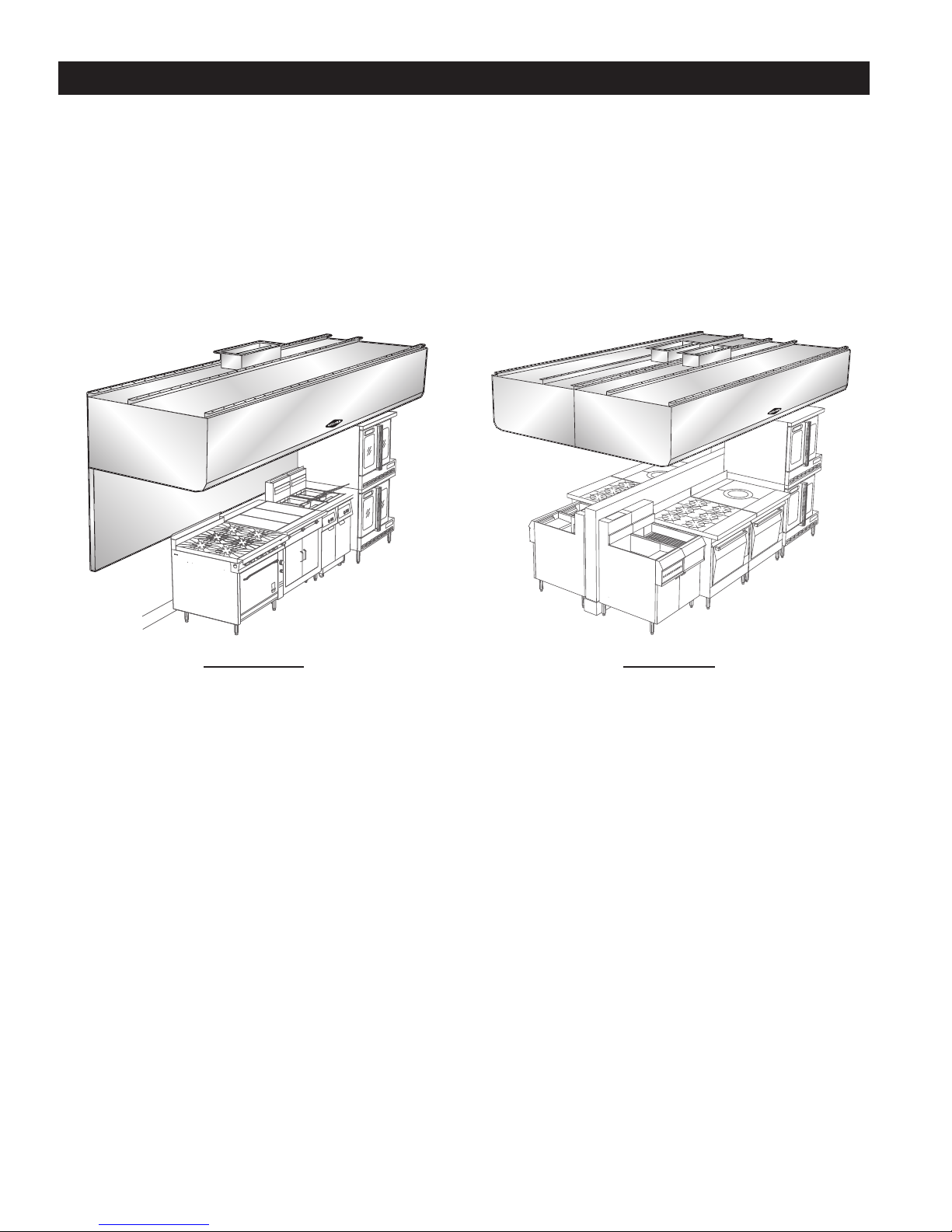
Both the ELXC and ELXC-UVi Venlators come in many dierent models as illustrated below. Your Venlator
may appear slightly dierent as they may have been custom designed to t the space and applicaon.
Figure 1-2-1
Model ELXC Series
Wall Mounted Canopy Shown With
Oponal Capture Wall
Figure 1-2-2
Model ELXC-BB Series
Island Style for all Double Island Arrangement

1-3
Chapter 1 - Introducon
Model Number Sequence
Gaylord Venlator model numbers are made up of an alphabec prex followed by a series of alphabec
and/or numeric suxes to designate the style of venlator and various opons. Sequence of model num-
bers is as follows.
1._____ 2._____ 3._____ 4._____ 5.______ 6._____ 7._____ 8.______ 9._____
Series Damper
Type
Style Front Lip
Design
(Opon)
Apron
Design (If
Applicable)
Canopy
Front
Height
(Opon)
Solid fuel AutoStart Hood
Depth
Denion of Prexes and Suxes
1. Series
ELXC ……………………… High Efficiency Water Wash Ventilator incorporating XGS Extractors.
ELXC-UVi ................. High Efficiency Water Wash Ventilator incorporating XGS Extractors and UV
treatment.
2. Damper Type
GFBD.........................Gaylord Fire Balancing Damper. Has an electric, thermostatically activated Fire/
Balancing damper located at the duct collar with back draft feature. 250°F N.C.
Thermostat standard.
GEBD …………………… Gaylord Electric Balancing Damper. Has an electric balancing damper located at
the duct collar with back draft feature.
GBD …………………….. Gaylord Balancing Damper. Mechanical balancing damper located at the duct
collar with internal set.
GBD-ES ………………… Gaylord Balancing Damper. Mechanical balancing damper located at the duct
collar with external set.
ND ………………………. No Damper.
3. Style
Blank ……………… Wall mounted canopy style.
CL …………………… Island style for single line of cooking equipment using one extraction chamber
(Light to Medium Duty only).
BBC-CL …………… Island style for single line of equipment using one extraction chamber with one
common exhaust duct.
BBC ………………… Island style for double line of cooking equipment using on one extracon chamber and
one common exhaust duct.
BB …………………… Island style for double line of equipment using two extraction chambers and two
separate exhaust ducts
4. Front Lip Design (Front lower edge of the hood)
Blank ..................... Facetted front design with 6 inch return flange. (3 Break or greater at front lip)
(CL models to have a maximum of 9”).
S............................ Square front with 6 inch “Super Capture” lip.
1-4
5. Apron Design Designation
Blank ...................... Capture wall to be added below hood. (Note: Water Wash drain to run out bottom
of capture wall. Access to drain connections to go into capture wall.)
A............................. Hood to have an apron, which will terminate at the bottom lower edge of the
canopy. (No interconnecting drains).
UW......................... Gaylord UDS to be incorporated into capture wall. (Mixed Intertek and UL listing
required).
Chapter 1 - Introducon
Denion of Prexes and Suxes – Cont.
6. Front Canopy Profile Option
Blank ..................... 30 inch or greater canopy height.
MP......................... Medium Profile – Any hood with a front height between 24 inches to 30 inches.
LP .......................... Low Profile - 12 inch to 23 inch front height.(Considerations for proper capture
and contain need to be considered with this option).
7. Solid Fuel Equipment (If Applicable – 700°F Applications only)
Blank………………...... Cooking equipment powered by sources other than the burning of wood.
SPA……………………… Hood use “XGS-SPA” Spark Arrestor Extractors – Intended applications that utilize
the burning of wood as a heat source.
8. AutoStart Opon
Blank ...................... Indicates the hood section does not have Autostart system as required by IMC.
AS ………………………. Indicates the hood section has Autostart conforming with the IMC requirement.
DCV-F …………………… Indicates the hood is equipped with an AutoStart system conforming with the IMC
requirement complying with IMC IECC, Calif. Title 24, IGCC, and ASHRAE Std. 90.1 /
189.
DCV-FH……………….... Indicates the hood is equipped with a DCV system for a single fan mul-hood
applicaon.
9. Hood Depth (Outside of Structural wall to front of hood canopy)
(##)......................... Value in inches to indicate the hood depth.
Chapter 1 - Introducon
Model Number Sequence

2-1
Chapter 2 - Principles of Operaon
ELXC Series
ELXC Series
Turning On the Exhaust Fan
Cauon: Always turn on the exhaust fan before turning on the cooking equipment.
Cauon: The chemical re exnguishing system may discharge if the exhaust fan is not on while the cook-
ing equipment is on or sll hot.
Cauon: Never operate your Venlator without the XGS Extractors in place or the Extractor Access Doors
open (Refer to Figure 2-2-2).
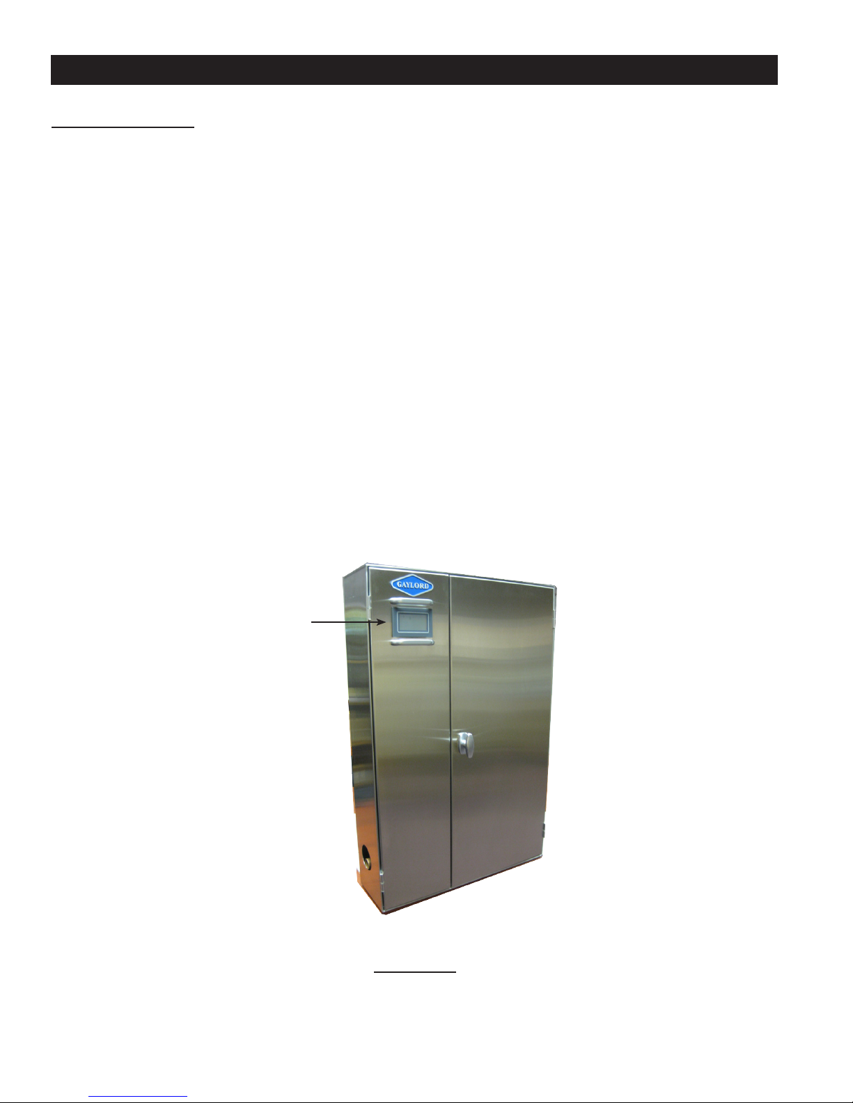
Operaon of the exhaust fan is controlled by the Gaylord Command Center, which is mounted in the Wash
Control Cabinet (refer to Figure 2-2-1). To start the exhaust fan push “START FAN” on the Command Center.
The Command Center control may be programmed to automacally start at a specic me. Refer to the
Operaon and Maintenance Manual for the Gaylord Command Center for complete operang instrucons.
Note 1: The ELXC Series Venlator may be equipped with a Gaylord Electric Balancing Damper, designat-
ed “GEBD” in the Venlator model number, or a Gaylord combinaon Fire/Balancing Damper, designated
“GFBD” in the model number. The Venlator model number can be found on the Venlator Nameplate (Refer
to page 2-19 for informaon on Balancing Dampers and page 5-11 for a sample of the Nameplate). If the
Venlator includes one of these dampers, when the fan is started the damper moves from the closed to open
posion, and it will take approximately 45 seconds for the exhaust to come up to 100%.
Note 2: Typically ELXC Series Venlators installed in the United States are equipped with a Gaylord Auto-
start Controller that automacally turns on the exhaust fan if the temperature at the sensors mounted in
the canopy exceeds 90°F. (Refer to Figure 2-2-2). In some instances Venlators installed outside the United
States will include an Autostart Control. Inclusion of an Autostart Control is designated by the sux “AS” or
“DCA” in the model number. The Venlator model number can be found on the Venlator Nameplate (refer
page 5-11 for a sample of the Nameplate). Refer to the Operaon and Maintenance Manual for the Gaylord
Command Center for complete informaon on the Autostart Control.
Grease Extracon
Grease is extracted by the use of Gaylord Model XGS Extractors located behind the Extractor Access Doors
(Refer to Figure 2-2-2). The hot contaminate-laden air rising from the cooking surface enters the inlet slot,
turns and is drawn through the Extractors where a high percentage of the grease and other parculate are
extracted from the air stream. The extracted liquid grease will drain down the Extractors and into the Grease
Canal which then drains into the Grease Guer. The scky grease will remain in the Extractor. The Extractors,
Grease Canal and Grease Guer are washed periodically by the automac Wash Cycle, while the fan is on.
The Gaylord Industries Model XGS Extractor is designed to deliver the absolute opmum in collecon e-
ciency at the lowest possible pressure drop. The Extractors are ETL Recognized as part of the ELXC Venlator.
They are constructed of corrosion resistant stainless steel.

2-2
Chapter 2 - Principles of Operaon
ELXC Series - Cont.
Figure 2-2-1
Wash Control Cabinet
Figure 2-2-2
Grease Extracon
Autostart Sensor
Extractor Access Door
Inlet Slot
Grease Laden Air
Balancing Damper
Gaylord Model
XGS Extractors
Grease Canal
Grease Gutter
Drain
Command Center

2-3
Chapter 2 - Principles of Operaon
ELXC Series - Cont.
Turning O the Exhaust Fan
Cauon: Always turn o the cooking equipment and allow to cool before turning o the exhaust fan. The
chemical re exnguishing system may discharge if the cooking equipment is on or hot when the exhaust
fan is o.
At the end of the cooking day, turn o the cooking equipment and allow to cool before turning o the ex-
haust fan. To turn o the exhaust fan push “STOP FAN” on the Gaylord Command Center (Refer to Figure
2-2-1). The Command Center control may be programmed to automacally turn o the exhaust fan at a spe-
cic me. Refer to the Operaon and Maintenance Manual for the Gaylord Command Center for complete
operang instrucons.
Note 1: If the Venlator is equipped with a Gaylord Autostart Controller, the exhaust fan will stay on if the
temperature at the sensor mounted in the canopy exceeds 90°F. (Refer to Figure 2-2-2). Once the tempera-
ture drops below 90°F., the fan will connue to run for 15 minutes and then shut o.
Note 2: If the Venlator is equipped with a Gaylord Electric Balancing Damper, designated “GEBD” or a
Gaylord combinaon Fire/Balancing Damper, designated “GFBD”, when the fan is turned o the damper will
move from the open to closed posion and remain closed unl the exhaust fan is re-started. Closing the
damper saves building energy by not allowing condioned air from draing up the exhaust duct, or in cold
climates prevents cold air from coming down the duct and into the kitchen.
Wash Cycle
Wash Cycle - Overview
The ELXC Series is referred to as a clean in place Venlator as it has automac Wash Cycles that washes away
the extracted grease within the Extractors, Plenum and surrounding areas, with hot, detergent injected wa-
ter. The grease is ushed down into the Grease Guer which slopes to a drain line which leads to the build-
ing drain system.
The Venlator has two wash manifolds, the Extractor Wash Manifold, to wash accumulated grease out of the
Extractors, and the Plenum Wash Manifold to wash the accumulated grease out of the Plenum area (Refer
to Figure 2-4-1 and 2-4-2). The two manifolds are independently connected to the Wash Control Cabinet,
Figure 2-2-1, typically located in, or near the kitchen (Refer to Figure A-5-1 in the Appendix on page A-5 for
a typical arrangement of the Wash Control Cabinet and Venlator). The Wash Control Cabinet houses the
Command Center, valves, detergent pump, detergent tank and other plumbing components needed to op-
erate the Wash Cycles. (Refer to Figure 2-15-1 on page 2-15 for a detailed illustraon of the Wash Control
Cabinet). Two electric solenoid valves are located on the top of or near the top of each Venlator secon
(Refer to Figure A-5-1).
Wash Cycle Sequence
The two wash manifolds, Extractor Wash and Plenum Wash, operate independently of each other as the
Extractor, Grease Canal and Grease Guer typically need washing more frequently than the Plenum area.
Timers in the Command Center are programmed to iniate either the Extractor Wash or Plenum Wash based
on the number of hours the exhaust fan has been on.
2-4
Chapter 2 - Principles of Operaon
ELXC Series - Cont.
Wash Cycle Sequence – Cont.
The frequency and the length of the Wash Cycle is determined by the type of cooking equipment involved;
Light Duty, Light/Medium Duty, Medium Duty, Heavy Duty, and Extra Heavy Duty. Refer to Table T-2-16-1,
Typical Example of Frequency and Length of Wash Cycles, on page 2-16 for typical applicaon. Washing the
Venlator based on hours of operaon for specic Dues of equipment provides the opmum in cleaning
performance with the lowest possible water and detergent consumpon.
Wash Cycle Example
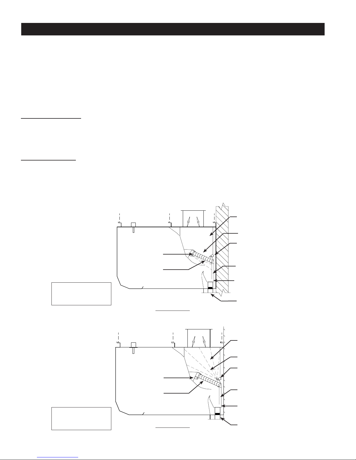
Extractor Wash Cycle – The Extractor Wash Cycle only comes on while the exhaust fan is on, typically dur-
ing cooking (Refer to Figure 2-4-1). Using Table T-2-16-1 on page 2-16, if the cooking equipment under the
Venlator is Heavy Duty then the Extractor Wash would come on every 4 hours of fan operaon, stay on for
3 minutes and then shut o. Refer to page 2-15 for addional details on the wash cycles.
Plenum Wash Cycle - The Plenum Wash Cycle only comes on while the exhaust fan is o (Refer to Figure 2-4-
2). Using Table T-2-16-1 on page 2-16, if the cooking equipment under the Venlator is Heavy Duty then the
Plenum Wash would come on every 16 hours of exhaust fan operaon, stay on for 3 minutes and then shut
o. Typically the Plenum Wash Cycle will begin, if the number of fan on hours has been sased, immedi-
ately aer the exhaust fan has been shut o. Refer to page 2-15 for addional details on the Wash Cycles.
Figure 2-4-1
Extractor Wash On
Figure 2-4-2
Plenum Wash On
Plenum Area
Plenum Area
Extractors
Plenum Wash Sprays
Plenum Wash
Manifold
Plenum Wash
Manifold
Grease Canal
Grease Canal
Grease Gutter
Grease Gutter
Extractor Wash
Sprays
Extractors
Drain
Drain
Extractor Wash
Manifold
Extractor Wash
Manifold
Note: Extractor Wash
comes on only when the
Exhaust Fan is On.
Note: Plenum Wash
comes on only when the
Exhaust Fan is O.

2-5
Chapter 2 - Principles of Operaon
ELXC Series - Cont.
Fire Protecon
Fire Damper
The ELXC Series Venlator may be equipped with a combinaon Gaylord Fire/Balancing Damper, designated
“GFBD” in the Venlator model number. If equipped, a 250°F. thermostat will be mounted at the entrance
of the exhaust duct collar (Refer to Figure 2-6-1). In the event of a re and if the thermostat reaches 250 °
F., the following will occur:
1. The re damper will close prevenng re from extending into the exhaust duct and fan.
2. The exhaust and supply fans will shut o.
3. If the Venlator was in a Wash Cycle it would shut o.
4. If the Command Center is wired to a building re alarm system the alarm will acvate.
5. If the Command Center is wired to a building management system it will nofy of a re condion.
6. Once the thermostat cools below its set point, the exhaust and supply fans can be re-started by
pushing “START FAN” on the Command Center.
Fire Exnguishing Systems
The Naonal Fire Protecon Associaon Standard 96 (NFPA-96) and the Internaonal Fire Code (IFC) requires
the use of a Fire Exnguishing System to cover the cooking surfaces, Venlator exhaust plenums (the area
behind the grease extractors), and the exhaust duct (Refer to Figure 2-6-1). Upon acvaon of the Fire Ex-
nguishing System the follow will occur:
1. Fire exnguishing agent will discharge through the cooking equipment nozzles, the plenum nozzles
and the duct nozzle(s).
2. The protected cooking equipment and possibly other cooking equipment will shut o. Refer to the
above referenced codes for specic equipment that must shut o.
3. If the Fire Exnguishing System is wired to a building re alarm system the alarm will acvate.
4. If the Fire Exnguishing System is wired to a building management system it will nofy of a re con-
dion.
5. The Fire Exnguishing System should be wired to the Gaylord Command Center. If it is, the following
will occur:
a) If the exhaust and supply fan were on the exhaust fan would stay on and the supply fan would
shut o. If the exhaust and supply fans were o, the exhaust fan would come on and the supply
fan would stay o.
b) If the Venlator Wash Cycle was on it would shut o.
c) If the Venlator is equipped with a Gaylord Electric Balancing Damper (model GEBD) or a Gay-
lord Fire/Balancing Damper (model GFBD) the damper will open.
6. Aer discharge, the Fire Exnguishing System must be recharged and cered by a re system con-
tractor and all exnguishing agent cleaned up before the cooking equipment can be turned back on.
For Operaon and Maintenance of the Fire Exnguishing System, refer to the system manufacture’s Owner’s
Manual.
Important: NFPA-96 requires inspecon and cercaon of re systems every 6 months.

2-6
Chapter 2 - Principles of Operaon
ELXC Series - Cont.
Figure 2-6-1
Fire Exnguishing System Discharge
Fire Extnguishing System
Duct Detector
250°F Thermostat
Used only when a Gaylord Fire
Balancing Damper (Model GFBD)
is used.
Fire Extinguishing System
Plenum Nozzle(s)
Fire Extinguishing System
Cooking Equipment Nozzles
*Illustration shows Fire Extinguishing System discharging.
Fire Extinguishing System
Cooking Equipment
Detectors
Fire Extinguishing System
Duct Nozzle
When a Fire Extinguishing System discharges, the
Balancing Damper remains open or opens if it was
closed. If equipped with a Model GFBD Damper
and the thermostat activates, the damper closes.

2-7
Chapter 2 - Principles of Operaon
ELXC-UVi Series
Ultraviolet Systems (UV)
Overview
Venlators incorporang UV Lamps are designated Model ELXC-UVi Series Venlators. UV Systems are used
to remove a high percentage of grease that the Extractors cannot remove, oering many benets to the
owner/operator. The UV Lamps are mounted in a UV Module which slide into a track downstream (aer)
the XGS Extractors (refer to Figure 2-10-1). The electronics and ballasts for UV System are mounted in a UV
Ballast Box which is located on the top of the Venlator (refer to Figure 2-10-1). The ELXC-UVi Venlator
is equipped with UV Status Lights to monitor the status of the UV System, and Safety Interlocks to protect
operators from exposure to UV light (refer to Figure 2-8-1).
For proper UV operaon, the Venlators must be maintained in good working order. The UV system must be
inspected periodically and the lamps replaced as necessary. The Venlator, ductwork and exhaust fan must
be inspected in accordance with NFPA-96 or local guidelines, though frequency of duct cleanings should be
signicantly reduced.
UV Safety
Cauon: Exposure to UV light is harmful to skin and eyes.
The ELXC-UVi Venlator is equipped with panels and Safety Interlocks to protect operators from direct expo-
sure to UV light. All safety precauons called for in this manual must be followed to avoid the potenal for
harm to operators or service personnel. Refer to Page 3-3 for complete descripon of safety precauons.
Turning On the Exhausng Fan and UV System
Cauon: Always turn on the exhaust fan before turning on the cooking equipment.
Cauon: The chemical re exnguishing system may discharge if the exhaust fan is not on while the cook-
ing equipment is on or sll hot.
Cauon: Never operate the Venlator without the XGS Extractors in place or the Extractor Access Doors
open (Refer to Figure 2-10-1).
Operaon of the exhaust fan and UV Lamps is controlled by the Gaylord Command Center (refer to Figure
2-9-1). To start the exhaust fan and turn on the UV Lamps push the “START FAN” buon on the Command
Center. The Command Center control may be programmed to automacally start the exhaust fan at a spe-
cic me. Refer to the Operaon and Maintenance Manual for the Gaylord Command Center for complete
operang instrucons of the Command Center.
Note 1: The ELXC-UVi Series Venlator may be equipped with a Gaylord Electric Balancing Damper, desig-
nated “GEBD” in the Venlator model number, or a Gaylord combinaon Fire/Balancing Damper, designated
“GFBD” in the model number. The Venlator model number can be found on the Venlator Nameplate (Refer
to page 2-19 for informaon on Balancing Dampers and page 5-11 for a sample of the Nameplate). If the
Venlator includes one of these dampers, when the fan is started the damper moves from the closed to open
posion, and it will take approximately 45 seconds for the exhaust to come up to 100%.
2-8
Chapter 2 - Principles of Operaon
ELXC-UVi Series - Cont.
Turning On the Exhausng Fan and UV System – Cont.
Note 2: Typically ELXC-UVi Series Venlators installed in the United States are equipped with a Gaylord Au-
tostart Controller that automacally turns on the exhaust fan if the temperature at the sensors mounted in
the canopy exceeds 90°F. (Refer to Figure 2-10-1). In some instances Venlators installed outside the United
States will include an Autostart Control. Inclusion of an Autostart Control is designated by the sux “AS” or
“DCA” in the model number. The Venlator model number can be found on the Venlator Nameplate (Refer
to page 5-11 for a sample of the Nameplate). Refer to the Operaon and Maintenance Manual for the Gay-
lord Command Center for complete informaon on the Autostart Control.
Note 3: The UV Lamps will not come on unless all the XGS Extractors are in place and the Extractor Access
Doors are closed as shown in Figure 2-10-1 and 2-10-2.
Note 4: The UV Lamps will not come on unless all the UV Module Access Doors are closed and latched as
shown in Figure 2-10-2.
Note 5: The UV Lamps will not come on unless the exhaust fan is running.
UV Status Lights
Each Venlator secon contains a bank of UV Status Lights to monitor the UV System (refer to Figure 2-8-1).
There are three colored lights, Blue, Yellow and Green. They indicate the system status as follows:
1. Green On: The UV system is operang properly.
2. Yellow On: One or more UV Lamps are not operang. If the yellow is on, less UV is being generated,
however it does not prevent the operaon of the Venlator or indicate an unsafe condion.
3. Blue On: One or more XGS Extractors are not in place and/or one or more UV Module Access Doors are
not closed properly, or the internal temperature of the Ballast Box has exceeded 118° F. which acvates
the High Temperature Shutdown Controller. During this mode the UV System is not operang and is in a
UVi System Standby mode unl the cause has been corrected.
In addion to the Status Lights on the Venlator, the Gaylord Command Center displays text indicang a simi-
lar message as the Status Lights. Refer to the Operaon and Maintenance Manual for the Gaylord Command
Center for complete operaonal instrucons.
Note: If either the Yellow or Blue light are on refer the Troubleshoong secon of this manual beginning on
page 4-1 for correcve acon.
Figure 2-8-1
UV Status Lights
UVi
SYSTEM
ON
UVi
LAMP
FAILURE
UVi
SYSTEM
STANDBY
20385
SYSTEM STATUS
UVi Ventilator
Integrated DCV
2-9
Chapter 2 - Principles of Operaon
ELXC-UVi Series - Cont.
Grease Extracon
Grease is removed from the exhaust air by combinaon of the Gaylord Model XGS Extractors and the UV
Lamps (Refer to Figure 2-10-1). The hot contaminate-laden air rising from the cooking surface enters the
inlet slot, turns and is drawn through the Extractors where a high percentage of the grease and other par-
culate are extracted from the airstream. As the air enters the Plenum chamber, the grease parcles are
exposed to the ultraviolet light which oxidizes the parcles into a light gray powder which are deposited on
the Lamps, the Plenum chamber and in the exhaust duct. Some powder may exhaust out the exhaust fan.
The extracted liquid grease will drain down the Extractors and into the Grease Canal which then drains down
into the Grease Guer. The scky grease will remain in the Extractors. The Extractors, Grease Canal and
Grease Guer are power washed periodically, while the exhaust fan is on, by the automac Extractor Wash
Cycle. The UV Lamps are also washed periodically during a Plenum Wash Cycle. Refer to page 2-11 for de-
tails on the Wash Cycles.
The Gaylord Industries Model XGS Extractor is designed to deliver the absolute opmum in collecon ef-
ciency at the lowest possible pressure drop. The Extractors are ETL Recognized as part of the ELXC-UVi
Venlator. They are constructed of corrosion resistant stainless steel.
Figure 2-9-1
Wash Control Cabinet
Command Center
2-10
Chapter 2 - Principles of Operaon
ELXC-UVi Series - Cont.
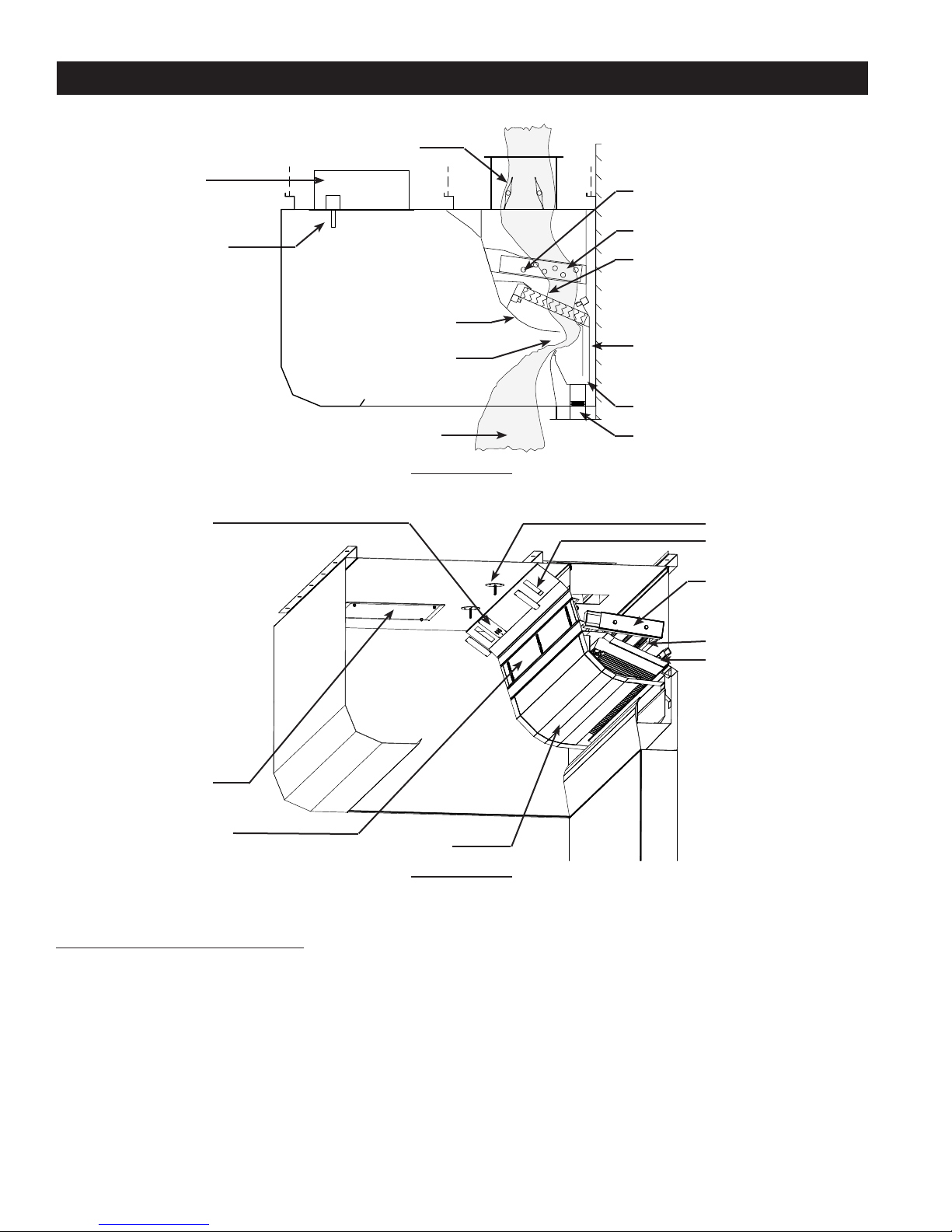
Figure 2-10-1
Grease Extracon
Figure 2-10-2
Model ELXC-UVi Series Cutaway
Turning O the Exhaust Fan
Cauon: Always turn o the cooking equipment and allow to cool before turning o the exhaust fan. The
chemical re exnguishing system may discharge if the cooking equipment is on or hot when the exhaust
fan is o.
At the end of the cooking day, turn o the cooking equipment and allow to cool before turning o the ex-
haust fan. To turn o the exhaust fan and UV Lamps push the “STOP FAN” buon on the Gaylord Command
Center (Refer to Figure 2-9-1). The Command Center control may be programmed to automacally turn o
the exhaust fan at a specic me. Refer to the Operaon and Maintenance Manual for the Gaylord Com-
mand Center for complete operang instrucons.
UV Module Access Door
Access to Ballast Box
UV Status Lights Autostart Sensor
Static Tap Opening
UV Lamp Module
UV Lamps
Extractor
Autostart Sensor
Grease Laden Air
Balancing Damper
Gaylord Model
EXG Extractors
UV Lamps
UV Module
Ballast Box
Accessable from
Underside
Grease Canal
Grease Gutter
Drain
Extractor Access Doors
Extractor Access Door
Inlet Slot

2-11
Chapter 2 - Principles of Operaon
ELXC-UVi Series - Cont.
Turning O the Exhaust Fan - Cont.
Note 1: If the Venlator is equipped with a Gaylord Autostart Controller, the exhaust fan will stay on if the
temperature at the sensor mounted in the canopy exceeds 90°F. (Refer to Figure 2-10-1). Once the tempera-
ture drops below 90°F., the fan will connue to run for 15 minutes and then shut o.
Note 2: If the Venlator is equipped with a Gaylord Electric Balancing Damper, designated “GEBD” or a
Gaylord combinaon Fire/Balancing Damper, designated “GFBD”, when the fan is turned o the damper will
move from the open to closed posion and remain closed unl the exhaust fan is re-started. Closing the
damper saves building energy by not allowing condioned air from draing up the exhaust duct, or in cold
climates prevents cold air from coming down the duct and into the kitchen.
Wash Cycle
Overview
The ELXC-UVi Series is referred to as a clean in place Venlator as it has automac Wash Cycles that washes
away the extracted grease within the Extractors, UV Lamps, Plenum and surrounding areas, with hot, deter-
gent injected water. The grease is ushed down into the Grease Guer which slopes to a drain line which
leads to the building drain system.
The Venlator has two wash manifolds, the Extractor Wash Manifold, to wash accumulated grease out of the
Extractors, and the Plenum Wash Manifold to wash the accumulated gray powder, created by oxidaon of
the grease by the UV Lamps, out of the Plenum area (Refer to Figure 2-12-1 and 2-12-2). The two manifolds
are independently connected to the Wash Control Cabinet typically located in, or near the kitchen (Refer to
Figure A-5-1 in the Appendix on page A-5 for a typical arrangement of the Wash Control Cabinet and Venla-
tor). The Wash Control Cabinet houses the Command Center, valves, detergent pump, detergent tank and
other plumbing components needed to operate the Wash Cycles (Refer to Figure 2-15-1 on page 2-15 for a
detailed illustraon of the Wash Control Cabinet). Two electric solenoid valves are located on the top of or
near the top of the Venlator (Refer to Figure A-5-1).
Wash Cycle Sequence
The two wash manifolds, Extractor Wash and Plenum Wash, operate independently of each other as the
Extractor, Grease Canal and Grease Guer typically need washing more frequently than the UV Lamps and
Plenum area.
Timers in the Command Center are programmed to iniate either the Extractor Wash or Plenum Wash based
on the number of hours the exhaust fan has been on. The frequency and the length of the Wash Cycle is de-
termined by the type of cooking equipment involved; Light Duty, Light/Medium Duty, Medium Duty, Heavy
Duty, and Extra Heavy Duty. Refer to Table T-2-16-1, Typical Example of Frequency and Length of Wash
Cycles, on page 2-16 for typical applicaon. Washing the Venlator based on hours of operaon for specic
Dues of equipment provides the opmum in cleaning performance with the lowest possible water and
detergent consumpon.

2-12
Chapter 2 - Principles of Operaon
ELXC-UVi Series - Cont.
Wash Cycle Sequence – Cont.
Wash Cycle Example
Extractor Wash Cycle – The Extractor Wash Cycle only comes on while the exhaust fan is on, typically dur-
ing cooking (Refer to Figure 2-12-1). Using Table T-2-16-1 on page 2-16, if the cooking equipment under the
Venlator is Heavy Duty then the Extractor Wash would come on every 4 hours of fan operaon, stay on for
3 minutes and then shut o. Refer to page 2-15 for addional details on the wash cycles.
Plenum Wash Cycle - The Plenum Wash Cycle only comes on while the exhaust fan is o (Refer to Figure 2-12-
2). Using Table T-2-16-1 on page 2-16, if the cooking equipment under the Venlator is Heavy Duty then the
Plenum Wash would come on every 16 hours of exhaust fan operaon, stay on for 3 minutes and then shut
o. Typically the Plenum Wash Cycle will begin, if the number of fan on hours has been sased, immedi-
ately aer the exhaust fan has been shut o. Refer to page 2-15 for addional details on the Wash Cycles.
Figure 2-12-1
Extractor Wash On
Figure 2-12-2
Plenum Wash On
UV Lamps
Plenum Area
Extractors
Plenum Wash
Manifold
Grease Canal
Grease Gutter
Extractor Wash
Sprays
Drain
Extractor Wash
Manifold
Note: Extractor Wash
comes on only when the
Exhaust Fan is On.
Plenum Area
Plenum Wash Sprays
UV Lamps
Plenum Wash
Manifold
Grease Canal
Grease Gutter
Extractors
Drain
Extractor Wash
Manifold
Note: Plenum Wash
comes on only when the
Exhaust Fan is O.
This manual suits for next models
1
Table of contents
Other GAYLORD Fan manuals


