Gaymar Medi-Temp III FW600 Series User manual

P/N 11294-000 11/01
Medi-Temp III REF FW600 Series Blood/Fluid Warmer
[ENGLISH]
Réchauffeur de sang/liquide Medi-Temp III série REF FW600 [FRANÇAIS]
Riscaldatore per sangue/fluidi Medi-Temp III serie REF FW600 [ITALIANO]
Recalentador de sangre y fluidos Serie REF FW600 Medi-Temp III [ESPAÑOL]
Aquecedor de Sangue/Líquidos Medi-temp III Série REF FW600 [PORTUGUÊS]
Medi-Temp III REF FW600-Serie Blut-/Flüssigkeitswärmer [DEUTSCH]
Medi-Temp III REF FW600 Series bloed-/vloeistofverwarmer [NEDERLANDS]
Medi-Temp III serie REF FW600 varmeaggregat til blod/væske [DANSK]
Medi-Temp III värmeaggregat för blod/vätska serie REF FW600 [SVENSKA]
Medi-Temp III REF FW600 -sarjan veren/nesteenlämmitin [SUOMI]
Medi-Temp III REF FW600-serie blod-/væskeoppvarmer [NORSK]
Óýóôçìá ÈÝñìáíóçò Áßìáôïò/Õãñþí Medi-Temp III ôçò ÓåéñÜò REF FW600 [ÅËËÇÍÉÊÁ]
Operator’s Manual/Service Manual
Manuel d’utilisation/Manuel d’entretien
Manuale per l’operatore/Manuale di manutenzione
Manual del operador/Manual de servicio
Manual do Utilizador/Manual de Serviço
Bedienungs-/Wartungshandbuch
Bedieningshandboek/Onderhoudshandboek
Operatørhåndbog/Servicemanual
Instruktionsbok/Servicehandbok
Käyttäjän käsikirja/huoltokäsikirja
Brukerhåndbok/servicehåndbok
Åã÷åéñßäéï ×ñÞóçò/Åã÷åéñßäéï ÓõíôÞñçóçò

Table of Contents
Sec Topic Page
1.0 Indications for Use ......................................... 1
2.0 Product Description ...................................... 2
3.0 Instructions for Use....................................... 4
4.0 Safety Systems ................................................. 7
5.0 Cleaning ............................................................ 7
6.0 Functional Check/Safety Inspection........... 8
7.0 Troubleshooting ........................................... 10
8.0 Technical Specifications .............................. 11
Before you begin . . .
Important
Before using the Medi-Temp III FW600 Series Blood/
Fluid Warmer, please read and understand this
Operator’s Manual and the SAFETY PRECAUTIONS prior
to use.
If you have any questions, please contact your local
dealer for assistance.
Warranty
The Medi-Temp III FW600 Series Blood/Fluid Warmer
is warranted free of defects in material and
workmanship for a period of one (1) year.
The Disposable Warming Sets are warranted free of
defects in material and workmanship for a single
application.
A copy of the warranty is available upon request.
Gaymar disclaims all implied warranties including, but
not limited to, the implied warranties of
merchantability and of fitness for a particular purpose.
ENGLISH

1.0 Indications for Use
This device is intended to aid in the prevention of
inadvertent hypothermia during administration of
blood, blood products, and other fluids.
1.1 Safety Precautions
DANGER
Risk of electric shock.
No user serviceable parts inside.
•US Federal law restricts this device to sale by
or on the order of a physician.
•Do not immerse in cleaning and/or
sterilization solution. Do not submerge or
soak unit; it is fluid resistant, not fluid proof.
•For grounding reliability of the Blood/Fluid
warmer, plug only into a properly grounded
outlet.
•The RUN/STANDBY switch does not provide
isolation from the mains. Isolation from the
mains (IEC 601-1) can only be achieved by
disconnecting the cord from the mains.
CAUTION
WARNING
•All air must be removed from the fluid lines
prior to connection to the patient.
•Monitor the fluid lines to insure they are air
free. Never administer fluids if there are air
bubbles in the line between the bubble trap
and the patient connector.
•Monitor the fluid level in the bubble trap
frequently. Bubbles released during heating
are captured in the trap. To refill the trap,
insert a sterile syringe into the valve and draw
air out until the trap is (2/3) full. Do not allow
the bubble trap to go below one-quarter
(1/4) full.
•The bubble trap must be kept mounted and
in the vertical position at all times.
Failure to follow the above warnings
could result in the introduction of air to
the patient. Introduction of air to the
patient could result in death or serious
injury.
1
ENGLISH

Figure 1—FW600 series Blood/Fluid Warmer
When this occurs, an LED temperature display located
on the front panel will display the actual fluid
temperature or the setpoint temperature in °C.
The setpoint is user selectable from 38.0°C–43.0°C
in 1.0°C increments, by use of the SETPOINT switch on
the front panel. Also located on the front of the unit is
a slot for insertion of the disposable warming set. On
the right side of the unit, just below the IV pole clamp,
is a receiver for the disposable warming set’s bubble
trap.
2.2 Disposable sets
The Medi-Temp III FW600 Series Blood/Fluid warming
unit is designed to be used only with Gaymar D25000
series disposable warming sets. The following warming
sets (figure 2) are designed for use up to 300 mm Hg
pressure. Contact your local dealer for more
information.
2.0 Product Description
The Medi-Temp III FW600 Series Blood/Fluid Warmer
is a dry-heat device designed for safe and rapid
warming of blood, blood products and other fluids
through the utilization of disposable blood/fluid
warming sets. The warmer does not provide fluid flow
rate control. Blood, blood products and other fluids
normally refrigerated, can be rapidly warmed to user
selectable temperatures of between 38.0°C–43.0°C
at flow rates up to 300 ml/min. Room temperature
fluids can be warmed at flow rates up to 500 ml/min.
The disposable Blood/Fluid warming sets are available
in Standard, Standard with Extensions, Pediatric, and
High Flow models.
2.1 Warmer
The warming unit is designed to be IV pole
mounted. The device has no on/off switch.
Connection to the AC supply is indicated by a
green STANDBY mode indicator, located on the
front panel. In STANDBY mode, no power can be
applied to the heater. To begin normal operation,
the RUN/STANDBY button must be pressed.
2
ENGLISH
RUN /STANDBY
switch
IV pole clamp
SETPOINT switch
button
Cassette slot
Bubble trap
receiver
STANDBY
indicator
REMOVE FROM USE
indicator

Figure 3—Warming set and bubble trap
A
B
C
D
D
E
F
G
AettessaCelbixelF
BrotanimilEriAlaunaM
)evlaVfeileR(
CparTelbbuB
DpmalC
E)tneitaPot(reuLelaM
FreuLelameF
)ecruoSdiulF/doolBot(
GliaRediuGeulB
3
Figure 2—D25000 series warming sets
noitpircseDgolataC
rebmuN
noitacilppAgnimirP
emuloV
dradnatSEC04352Dnim/lm051—OVKlm93
noisnetxe"84htiwdradnatSEC01352Dnim/lm051—OVKlm84
noisnetxe"06htiwdradnatSEC51352Dnim/lm051—OVKlm05
noisnetxe"03htiwcirtaidePEC02352Dnim/lm001—OVKlm03
noisnetxe"84htiwwolFhgiHEC03352Dnim/lm005—001lm97
neposnievpeekotderiuqerwolfmuminim=OVK
ENGLISH

Figure 4—Inserting the cassette
3.0 Instructions for Use
(see figures 3—5)
•Attach warming unit to IV pole and secure
with clamp on side of unit.
•Plug the power cord into a properly
grounded outlet.
•Remove the warming set from it’s sterile
packaging
NOTE: The flexible warming set is designed so
it can be inserted into the warmer in only one
orientation. Orient the cassette so that the blue
guide rail is inserted into the bottom of the
warming unit.
Grasp each rail (see figure 4). Stretch the flexible
cassette slightly and insert the front end of the
cassette into the front of the warming unit, with
the blue guide rail facing down. Align the rails to
each of the slotted openings.
Move hands to the rail protrusions and continue
to insert the cassette until the clear guide rail is
almost flush with the front of the unit. (The blue
guide rail will protrude slightly for easy removal.)
4
Figure 5—Setup instructions
ENGLISH

•All air must be removed from the fluid lines
prior to connecting to the patient.
•Monitor the fluid lines to ensure they are air
free. Never administer fluids if there are air
bubbles in the line between the bubble trap
and the patient connector.
Failure to do so could result in the
introduction of air to the patient,
resulting in death or serious injury.
When fully inserted, the clear guide rail
should protrude no more than 0.5 cm from
the front of the warming unit. Failure to
fully insert the cassette may result in
damage to the cassette.
Close warming set input clamp. Remove the
protector from the female luer of the warming set
and connect it to the male luer on the IV
administration set. Remove the protector from
the male luer of the warming set. To minimize
temperature drop and priming volume, remove
unnecessary lead extensions at this time.
Invert the bubble trap.
Open warming set input clamp. Allow fluid to
prime the set. When the bubble trap fills to
approximately (2/3) full, close the output clamp.
Re-invert the bubble trap and place it into the
bubble trap receiver on the side of the warming
unit.
The bubble trap must be mounted and kept in
a vertical position at all times. Failure to do
so could result in the introduction of air
to the patient, resulting in death or
serious injury.
Press the RUN/STANDBY switch on the
front of the unit.
Upon successful completion of self-diagnostics,
the display will flash the setpoint for approximately
3 seconds, then begin warming the fluid to the
selected temperature.
The setpoint most recently used is retained
in memory, even after power is removed.
To select an alternate setpoint, first press the
SETPOINT switch momentarily.
This will cause the setpoint to be displayed and
flash for approximately 3 seconds. While the
display is flashing the setpoint, the user may select
any setpoint between 38.0°C and 43.0°C in 1.0°C
increments by repeatedly pressing the SETPOINT
switch.
NOTE: holding down the SETPOINT switch
indefinitely will not increment the setpoint.
After the selection has been made, the display will
continue to flash this setpoint for approximately
3 seconds, then revert to displaying the actual fluid
temperature. The setpoint can be checked at any
time during the procedure by momentarily
pressing the SETPOINT switch.
If required, connect an extension for patient
connection.
Purge air from remaining length of tubing by
opening output clamp and allowing fluid to flow.
WARNING
WARNING
5
Monitor the fluid level in the bubble trap
frequently. Bubbles released during heating
are captured in the trap. To refill the trap,
insert a sterile syringe into the valve and draw
air out until the trap is two-thirds (2/3) full.
Do not allow the bubble trap to go below
one-quarter (1/4) full.
Failure to monitor the fluid level in the
bubble trap could result in the
introduction of air to the patient,
resulting in death or serious injury.
WARNING
CAUTION
ENGLISH

3.1 Effect of Flow Rate on Fluid
Temperature
Fluid temperatures exiting the patient line are affected
by flow rate. The following flow vs. output fluid
temperature curve is typical for the FW600 series
warming unit. See figure 6 above.
NOTE: Output fluid temperature for this curve is
measured at the end of the patient line.
Figure 6—Typical fluid temperature vs. flow rate
6
3.2 Warming Set Removal
The cassette cannot be removed from the warming
unit while under pressure. To remove the cassette:
1. Close the warming set input clamp first, while
leaving the output clamp open.
2. Close the warming set output clamp.
3. Following steps 1 and 2 will allow fluid to drain
from the cassette. Gently pull on blue guide rail to
remove cassette from warming unit.
4. Dispose of warming set per facility protocol.
Failure to drain cassette will make it difficult
to remove. Forcing the cassette out may
cause it to rupture.
CAUTION
ENGLISH
qÉãéÉê~íìêÉ=~í=íÜÉ=båÇ=çÑ=m~íáÉåí=iáåÉ
OM
OR
PM
PR
QM
QR
M RM NMM NRM OMM ORM PMM PRM QMM QRM RMM RRM SMM
cäçï=áå=ãäLãáå
qÉãéÉê~íìêÉ=ø`
?eáÖÜ=cäçï=ïLQU?ÉñíÉåëáçåI
OMø=áåéìí=ÑäìáÇ?
?pí~åÇ~êÇ=ïLQU?ÉñíÉåëáçåI
NMø=áåéìí=ÑäìáÇ?
pÉíéçáåí=QPKMø` ^ãÄáÉåí=OOø`

7
4.0 Safety Systems
4.1 Over Temperature Protection
A backup system within the warmer is independent of
the main controller and monitors fluid temperature
continuously. If the output fluid temperature exceeds
45.0°C, the backup system will immediately interrupt
power to the heaters. If the over-temperature
condition is a temporary occurrence as a result of a
sudden change in flow rate, the display will alternately
flash HI and the fluid temperature. When the fluid
temperature returns to acceptable temperature levels,
normal operation will resume. If, however, the backup
system detects that the over-temperature condition is
a result of a failure of the main controller, an audible
alarm will sound, the RFU (REMOVE FROM USE)
indicator will light, and the device will shut down.
If this occurs, immediately stop the fluid flow, discard
the warming set, and contact your dealer for service.
4.2 Self-diagnostics
Each time the warming unit is switched from STANDBY
mode to RUN mode, a self-test is initiated. If the
backup system is not functioning properly, an error
message will be displayed and the unit will shut down.
In addition, self-tests are routinely performed during
RUN mode to ensure continued safe operation of the
warming unit.
4.3 Control Alarm LO
If the warming unit senses a fluid temperature less than
34.0°C, the audible alarm will chime and the display
will alternately indicate the symbol LO, and the actual
fluid temperature.
Exception: The unit will not alarm until the fluid
temperature has initially surpassed the
34.0°C threshold.
5.0 Cleaning
Do not immerse the warmer in cleaning or
disinfectant solutions. Do not submerge it in
liquids; it is fluid-resistant, not fluid-proof.
Immersion could result in malfunction
or equipment damage.
Perform the following care and cleaning between
patient use or per facility protocol.
• Unplug unit prior to cleaning
• To clean the external surfaces of the warmer, use
a non-abrasive cleaning solution (such as warm
soap water) and a clean cloth.
CAUTION
CAUTION
ENGLISH
• Clean inside of cassette slot with disposable brush.
Carefully flush using squeeze bottle with water.
Replacement cleaning kit P/N 78350-000.
• Apply a disinfectant such as 10% chlorinated
bleach solution (chlorinated bleach with 5.25%
sodium hypochlorite) to both the outside of the
unit and the cassette slot and allow to dry.
The warming unit should be cleaned if any
fluid or foreign substance has entered the
cassette slot. Failure to keep the cassette
slot clean could impede cassette
insertion.

8
6.0 Functional Check and Safety
Inspection
To assure optimum performance, dependability, and
safety, the following should be performed every twelve
months or as specified in the facility’s preventive
maintenance program.
Equipment or tools required
oAny Gaymar D25340 series Blood/Fluid
Warming Set
oTemperature measurement device:
• Gaymar D25340 Blood/Fluid Warming
Set; and
• Temperature sensor (Gaymar catalog
FWT1) and an ohmmeter (accuracy,
1.5% of reading; maximum excitation
current of 100uA) and the resistance
temperature chart. See figure 10 (p. 12).
or
• Any Gaymar D25000 series
Blood/Fluid Warming Set; and
• Waterproof temperature sensor/
meter with an accuracy of ± 0.3%
across the range of 30°C to 60°C
and a thermal time constant of 2
seconds or faster.
oFlow measurement device (Gaymar
catalog FWT2 flowmeter):
• Fluid source with calibrated flow
meter and a minimum accuracy of
± 12 ml/minute
or
• Fluid source with adjustable flow
control, Use a stop watch and
graduated cylinder to adjust flow
rate.
oCurrent Leakage/Ground resistance tester
oAC multimeter
6.1 Physical Inspection
Check that the following items are in good condition
and secure.
oLabels, if peeling or missing
oScrews in cover
oBubble trap receiver
oPower cord
oIV pole clamp
6.2 Output Fluid Temperature
Verification
The FW600 Series Blood/Fluid Warmer is factory
calibrated at a flow rate of 100 ml/min with a set point
of 43.0°C.
To verify the output fluid temperature is correct:
1. The ambient room temperature must be between
20°C to 24°C.
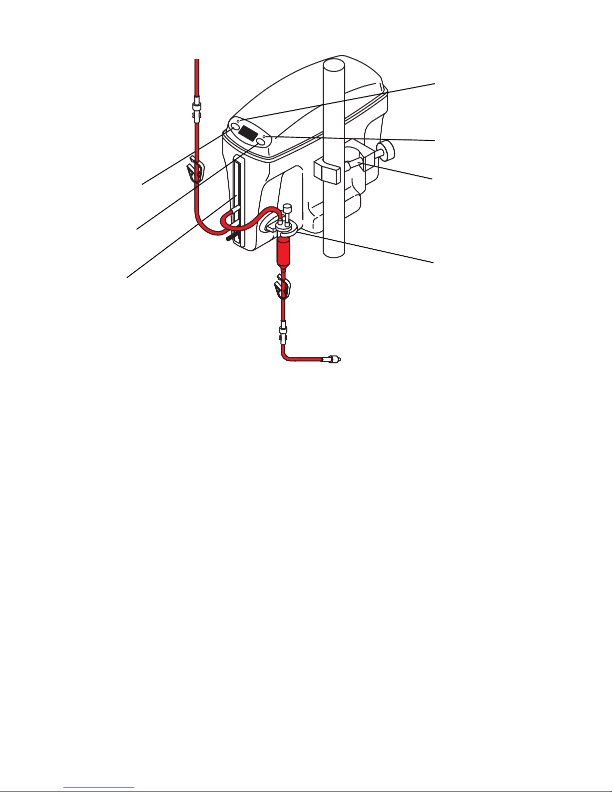
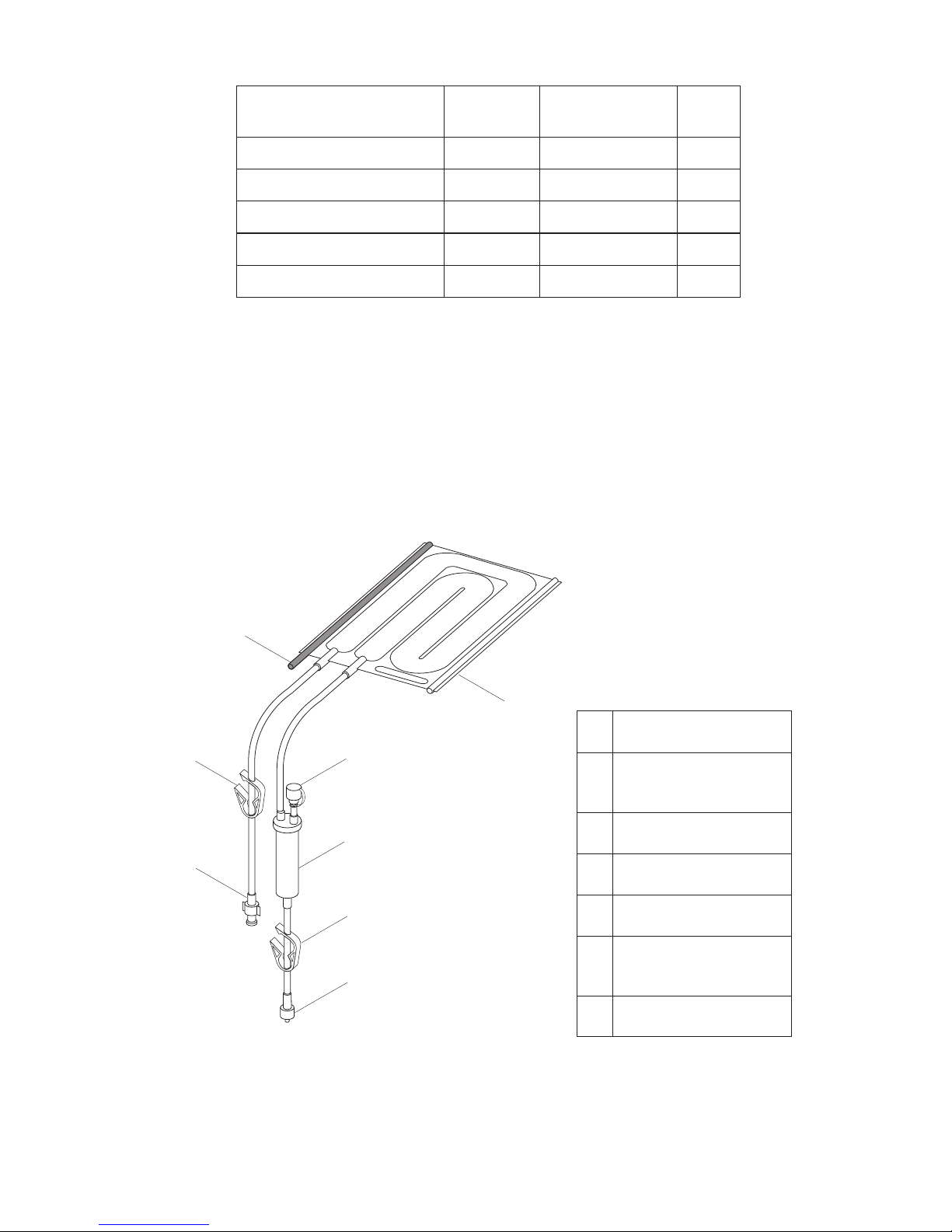
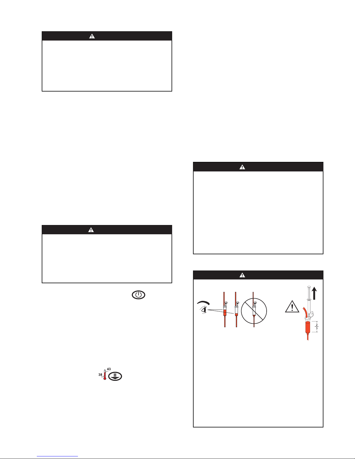
2. Connect the test setup (see figure 7). Attach the
Gaymar FWT1 temperature sensor to the output
of the bubble trap.
Alternate method: Put a hole in the top of the
bubble trap and insert a temperature
measurement device through this hole. Make
certain sensor is completely submerged in
fluid then seal the hole in the bubble trap.
3. Connect the FWT2 flowmeter or flow
measurement/control device to the output of the
FWT1 temperature sensor.
Alternate method: If using the sensor in the bubble
trap method, connect the FWT2 flowmeter or
flow measurement/control device directly to the
output of the bubble trap.
4. Flow room temperature water through the
warmer at 100 ml/min (cc/min). Verify that the
bubble trap is maintained 1/2 to 2/3 full.
5. Turn the warmer on. Adjust the SETPOINT to
43.0°C. Allow it to run for 10 minutes.
6. Verify that the output water temperature is
43.0°C ± 1.1°C. If using the FWT1 temperature
sensor and an ohmmeter, verify that the resistance
is within 1019—1112 ohms.
If temperature or resistance values are not
met, check setup and repeat test. If still not
within range, contact your dealer for service.
This device is factory calibrated and cannot be
field adjusted.
6.3 Overtemp Protection Verification
Proper operation of the overtemp protection system is
verified each time the unit is switched from STANDBY
to RUN mode. Therefore, periodic testing of this
system is not necessary. However, the following
procedure may be used to force an OVERTEMP
condition in order to observe that the overtemp
protection system works:
ENGLISH

9
1. Insert any D25000 series Warming cassette
into the warming unit. Using hot tap water
(46°C–50°C), flow hot water through the
cassette for approximately 1-3 minutes.
2. Connect AC power to the warming unit. The
device should immediately sound the audible alarm
and light the RFU light.
6.4 Ground Resistance Check
Use a current leakage/ground resistance tester to
measure the resistance between the ground pin on the
power plug and the mounting screw on the IV pole
clamp.
The resistance value should not exceed 0.50 ohms.
Figure 7—Test setup
6.5 Current Leakage Test
Measure the maximum earth leakage current (ground
open). Measure all combinations of line polarity with
neutral open and closed. Values should not exceed the
following;
FW600 neutral closed ...... 150µA
FW600 neutral open......... 200µA
FW603 neutral closed ...... 250µA
FW603 neutral open......... 300µA
ENGLISH

10
motpmySsesuacelbaborPnoitcaderiuqeR
sehsalfyletanretlayalpsiD
diulfehtdnaOL
erutarepmet
saherutarepmetdiulftuptuO
.C°43dehcaerteyton
.setunim2rofnurottinuwollA
,esaercnitonseoderutarepmetfI
.ecivrestseuqerdnaesumorfevomer
sehsalfyletanretlayalpsiD
diulfehtdnaIH
erutarepmet
sahcus,ecnabrutsidtneisnartA
,etarwolfniegnahcneddusa
erutarepmetdiulfehtdesuacsah
.C°34evobaesirot
lamronemuserlliwtinu—ENON
sporderutarepmetnehwnoitarepo
.C°34woleb
dnasdnuosmralaelbiduA
ehtdnaOLsehsalfyalpsid
erutarepmetdiulf
saherutarepmetdiulftuptuO
.C°43wolebdeppord
.setunim2rofnurottinuwollA
,esaercnitonseoderutarepmetfI
.ecivrestseuqerdnaesumorfevomer
dnasdnuosmralaelbiduA
_AFsetacidniyalpsid
evahscitsongaidcinortceleehT
.melborplanretninadetceted
.ecivrestseuqerdnaesumorfevomeR
sdnuosmralaelbiduA
wolleydnaylsuounitnoc
tilsithgilUFR
evahserutarepmetdiulflanretnI
pukcabdnaC°54dedeecxe
.detavitcaneebsahmetsys
dna,ettessacdracsid,wolfdiulfpotS
.ecivrestseuqer
ottluciffidsiettessaC
tinugnimrawotnitresni
otroirpdemirpettessaC
.noitresni
.tresnierdnaettessacniarD
yamtinugnimrawfotolsedisnI
ehtnonoitanimatnocevah
.setalpretaeh
gniwollofybtinufoedisninaelC
)0.5noitces(erudecorpgninaelc
ottluciffidsiettessaC
tinugnimrawmorfevomer
.dezirusserpllitssiettessaCtuptuonepodnapmalctupniesolC
.niardotdiulfwollA.pmalc
7.0 Troubleshooting
Figure 8—Troubleshooting chart
ENGLISH

11
snoitacificepSlacinhceT
metI006WF306WF
/egnartniopteS
noituloser
stnemercniC°0.1niC°0.34otC°0.83
erutarepmetdiulF
noituloser
C°1.0
taycaruccarellortnoC
nim/lm001
C°5.0±
egatloVCAV021.CAV042-022
tnerruCA9A5.4
esuFV052yaledemitA51)2(L,V052,A3.6,T)2(
mm02xmm5
ycneuqerFzH06zH06/05
erutarepmettneibmA
egnar
C°92otC°51
drocrewoP,TJSepytdetsilLU,gnoltf51
htiwdrocrotcudnoc-3GWA61
epyt-gnidnuorgno-dedlom
gulpedarglatipsoh
naylnoesU.gnolsretem6,4
)dezinomrah(lanoitanretni
egadrocgnisudrocrotcudnoc-3
rotcudnoc12-DHotdevorppa
)5.1G3FVV5OH(2mm5.1ezis
noitacifissalC,tnempiuqefoorphsalps,FBepyt,dednuorg1ssalC
citehtseanaelbammalfafoecneserpehtniesurofelbatiuston
rofelbatiuS.edixosuortinronegyxohtiwroriahtiwerutxim
.ytudsuounitnoc
yrotalugeRottcepserhtiwdeifissalC
dna,erif,kcohscirtcele
ni,ylnosdrazahlacinahcem
,1-1062LUhtiwecnadrocca
1.106.ON2.22CASC/NAC
1-10606NE
citengamortcelE
ytilibitapmoc
3991:2-1-10606NEsteeM
)tnempiuqeMSI1puorG,BssalCsadeifissalC11RPSIC(
thgieWgk7.2
eziSmc21xmc5.82xmc22
8.0 Technical Specifications
IPX4
Figure 9—Specifications
ENGLISH

12
.pmeT.siseR.pmeT.siseR.pmeT.siseR.pmeT.siseR.pmeT.siseR.pmeT.siseR.pmeT.siseR.pmeT.siseR.pmeT.siseR
)C°()smho()C°()smho()C°()smho()C°()smho()C°()smho()C°()smho()C°()smho()C°()smho()C°()smho(
5317418300311425114432017401905118355276584695185
1.5356411.8359211.1484111.4491011.747091.058081.352271.656461.95975
2.5395412.8309212.1434112.4451012.743092.055082.358172.654462.95775
3.5335413.8358213.1493113.4411013.740093.052083.356173.651463.95575
4.5374414.8397214.1443114.4470014.746984.059974.354174.659364.95375
5.5314415.8347215.1492115.4430015.743985.056975.351175.657365.95175
6.5353416.8396216.1452116.449996.749886.053976.359076.654366.95965
7.5392417.8346217.1402117.445997.746887.050977.356077.652367.95765
8.5332418.8395218.1461118.441998.742888.057878.353078.650368.95565
9.5371419.8345219.1421119.448899.749789.054879.351079.657269.95365
631141939421247011544898467815187458967552606165
1.6350411.9344211.2430111.540891.842781.158771.455961.75326
2.6300412.9393212.2489012.546792.849682.155772.453962.75026
3.6349313.9343213.2449013.542793.846683.152773.450963.75816
4.6388314.9392214.2409014.548694.842684.159674.458864.75616
5.6338315.9342215.2458015.545695.849585.157675.455865.75416
6.6377316.9391216.2418016.541696.846586.154676.453866.75116
7.6317317.9341217.2477017.547597.843587.151677.450867.75906
8.6366318.9390218.2437018.544598.849488.158578.458768.75706
9.6306319.9340219.2486019.540599.846489.155579.455769.75506
7355310499113446016464994348252575537685306
1.7394311.0459111.3406011.642491.940481.258471.550761.85006
2.7344312.0409112.3465012.649392.946382.257472.558662.85895
3.7383313.0458113.3425013.645393.943383.254473.555663.85695
4.7333314.0408114.3474014.642394.940384.251474.553664.85495
5.7372315.0467115.3434015.648295.947285.258375.550665.85295
6.7322316.0417116.3493016.644296.944286.255376.558566.85095
7.7361317.0466117.3453017.641297.941287.253377.555567.85785
8.7311318.0416118.3413018.647198.947188.250378.553568.85585
9.7360319.0475119.3472019.644199.944189.257279.551569.85385
Figure 10—Resistance temperature chart
(Gaymar FWT1 Temperature Sensor)
ENGLISH
Table of contents
Other Gaymar Food Warmer manuals