Gaymar Thermacare REF TC3249 User manual

Gaymar Industries, Inc.
10 Centre Drive
Orchard Park, NY 14127-2295 USA
Telephone: +1 716 662-8636
+1 716 662-2551
Fax: +1 716 662-0730
+1 716 662-6120
www.gaymar.com
Gaymar and Thermacare trademarks are registered
in the US Patent and Trademark Office.
©2010. Gaymar Industries, Inc.
All rights reserved.
Thermacare®REF TC3249
Convective Warming System
Service Manual
P/N: 100077000 Rev. C 11/10
Thermacare

Before you begin . . .
Important
•Refer to the TC3249 Convective Warming
System Operating Manual for detailed
operating instructions. Read and understand
the Operating Manual and all precautions prior
to using the Convective Warming System.
•Review the SAFETY PRECAUTIONS (see page
2) prior to servicing the Convective Warming
Power Unit.
•Fortechnicalassistance,contactyourlocal
dealer.
NOTE: Extremely high storage temperatures
(such as those found in rail cars or automobile
trunks on hot summer days) can cause the
thermostats within this device to actuate. Should
this occur, the REMOVE FROM USE indicator
will light when the Power Unit is turned on. If
this happens, the thermostats must be manually
reset. Refer to section 7, Functional Check and
Safety Inspection.
Attention: consult accompanying
documents
Dangerous voltage
Protective earth (ground)
Type BF applied equipment
MIN (Fan only)
LOW (90°F, 32°C)
MED (100°F, 38°C)
HIGH (110°F, 43°C)
Do not use in operating room
(OR) or Intensive Care Unit (ICU)
Off-on switch
REMOVE FROM USE
(indicator light, amber color)
Symbols used within this manual:
60°F -85°F
(16°C-2 9°C)
Ambient operating temperature
29
Section 13 - Wiring Diagram (cont’d)

Contents
Section Introduction Page
1.0 Safety Precautions................................................................2
2.0 Repair Policy / Return Authorization.......................................3
3.0 Specifications .......................................................................4
4.0 Theory of Operation ..............................................................5
5.0 Controls and Indicators .........................................................7
6.0 Preventive Maintenance ........................................................7
7.0 Functional Check and Safety Inspection.................................8
8.0 Inspection Form..................................................................16
9.0 Troubleshooting ..................................................................19
10.0 Repair Procedures ..............................................................21
11.0 Drawings/Parts List ............................................................24
12.0 Test Tool Schematic............................................................27
13.0 Wiring Diagram...................................................................28
Illustrations
Figure Description Page
1 Convective Warming System ...............................................5
2A/B Power Unit Mounting ........................................................... 5
3 Pole Mounting Height Limit..................................................5
4 Operator Control Panel.........................................................6
5 Test Tool..............................................................................9
6 Temperature Sensor Location .............................................10
7 Troubleshooting Chart - NO HEAT ...................................... 19
8 Troubleshooting Chart - NO AIR FLOW................................20
9 Drawing/Parts List..............................................................24
10 Drawing/Parts List..............................................................25
11 Drawing/Parts List..............................................................26
12 Test Tool Schematic ...........................................................27
13 Wiring Diagram .................................................................. 28
Tables
Table Description Page
1 Air Temperatures.................................................................. 4
2 Functional Check/Inspection Form.......................................16
Table of Contents
128
Section 13 - Wiring Diagram
Figure 13 - Wiring Diagram
ATTENTION
Sta tic-Sensitive
Dev ic es

2
1.0 Safety Precautions
Review the following SAFETY PRECAUTIONS prior
to testing the Power Unit. •After performing the thermostat test
procedure, verify that the Test Tool or any
installed test jumpers have been removed
before returning the Power Unit to patient
use.
Failure to remove the Test Tool or test
jumpers may result in death, serious
injury or equipment malfunction.
•AlwaysunplugthePowerUnitbefore
attaching or removing the Test Tool
or test jumpers and when resetting
thermostats. Failure to unplug the Power
Unitcouldresultinelectricalshockand
cause death or serious injury.
•Use only Gaymar replacement parts as
identified in the parts lists (pp. 24-27).
Useofsubstitutepartscouldleadto
power unit malfunction or patient injury.
•TheTemperatureControlPCBoardis
pre-set at the factory. Do not attempt to
calibrateit.AdjustmentoftheControl
PC Board in the field could result in
patient injury.
•Use care when resetting the thermostats.
Excessive force (force greater than
5 pounds) can damage the overtemp
protection device and/or inadvertently
alter the trip temperature of the device.
DANGER
•Explosivehazard.Donotuseinthe
presence of flammable anesthetics.
•Riskofelectricshock.Disconnectpower
before servicing the TC3249 Power Unit.
WARNING
WARNING
This device generates heated air flow.
Excessive heat could cause thermal
stressorskinlesions.Failuretofollow
these precautions could result in death or
serious injury:
•Use this system only under direction of
a physician. Read and understand the
Operating Manual, Quilt Instructions for
Use, and all precautions before using.
•Repairs should be performed only by
qualified personnel such as certified
biomedical electronics technicians or
certified clinical engineers familiar with
repair practices for servicing medical
devices, and in accordance with the
Service Manual. Damage to the Power
Unitormalfunctioncouldotherwise
result.
•AlwaysperformtheFUNCTIONAL
CHECK AND SAFETY INSPECTION after
makingrepairsandbefore returning the
PowerUnittopatientuse.Document
your findings on the INSPECTION
FORM. Improper repair may result
in death or serious injury, equipment
damage, or malfunction.
(continued next column)
Section 1 - Safety Precautions
•U.S.Federallawrestrictsthisdeviceto
sale by or on the order of a physician.
•For grounding reliability, plug only into a
grounded outlet labeled “Hospital Grade.”
•The HEPA filter must be installed correctly.
Failure to install the filter correctly will
prevent it from functioning properly and
could allow unfiltered air to reach the
patient.
•When using an I. V. pole, do not mount
the Power Unit higher than 3 feet
(0.9 meter). Otherwise, the Power Unit
could tip over.
Section 12 - Test Tool Schematic
ATTENTION
Static-Sensitive
Dev ic es
27
Figure 12 - Test Tool Schematic
(see Figure 11/11A)
Section 11 - Drawings/Parts Lists (cont’d)
Item Description Part
Number
30 Label, Caution 12762000
32 Cord strap assembly 03791000
33 Heater thermostat (S4) 78025000
34 Interlock switch 91375000
35 Sleeving 4 1/2" LG 81054000
- Power cord (Continental Europe) PC001
- Power cord (United Kingdom) PC002
- Power cord (Australia) PC003
- Power cord (Switzerland) PC004
- Power cord (Italy) PC005
- Power cord (Denmark) PC006
- Power cord (Israel) PC007
PC001PC004 PC006PC002 PC005PC007PC003
Item Description Part
Number
16 Power entry module 08993000
17 Motor kit 78022000
18 Patient limit thermostats (S2,S3) 91323005
19 Hose assembly 78423000
20 Kit, card, label replacement 78110000
21 Rear housing kit (includes labeling) 78118002
22 I.V. pole clamp 08614000
23 Toggle shoe 91439000
24 Card, Contraindication, Greek/Blank 09877000
25 Card, Contraindication, Swedish/Finnish 09876000
26 Card, Contraindication, Dutch/Danish 09875000
27 Card, Contraindication, Italian/German 09874000
28 Card, Contraindication, Spanish/ Portuguese 09873000
29 Card, Contraindication, English/French 09872000
Figure 11A - Plugs
CAUTION

2.0 Repair Policy
For customers who repair Gaymar Power Units at
their location, this manual contains information to
allow a qualified biomedical technician to make
necessary repairs.
2.1 Limited Warranty
The Thermacare TC3249 Power Unit is warranted
free of defects in material and workmanship
under normal use and operation for a period of
two years, under the terms and conditions of the
Gaymar warranty in place at time of purchase.
During the warranty period, Gaymar will repair
or replace at its sole option, free of charge, any
defective parts or products returned with prior
authorization prepaid to Gaymar Industries.
Consumable items such as filters are excluded.
The full warranty is available from Gaymar upon
request.
Warranty does not cover products abused,
misused, or altered outside the factory. There
are no obligations on the part of Gaymar for
consequential damages arising out of or in
connection with the use or performance of the
product. Gaymar disclaims all implied warranties
including, but not limited to, the implied
warranties of merchantability and of fitness for a
particular purpose.
2.2 In-Warranty Repairs
All in-warranty field repairs must be authorized by
Gaymar's Export Department before proceeding.
2.3 Out-of-Warranty Repairs
If the Power Unit becomes inoperative and the
cause cannot be determined, the complete
Power Unit may be returned to the factory for
servicing at the purchaser's expense. Please
contact Gaymar's Export Department to obtain a
returned goods (“RG”) number prior to returning
equipment.
2.4 ReturnAuthorization
Please contact your local dealer.
Section 2 - Repair Policy
3
Figure 11 - TC3146 Detail Drawing
Section 11 - Drawings/Parts Lists (cont’d)
26
To release wires from
terminal block, insert
a small screwdriver in
slot nearest wire and
pull towards center.
S3
S2
S4
16
17
18
19
22 23
24
20
21
25
26
27
28
29
30
32
33
34
35
ROTATION

HEAT
S3S2
OVERTEMP
THERMOSTAT
BYPASS
14
4
12
11
10
9
13
3.3 Temperature Settings
The air temperatures are identified on the operator
control panel and indicate the average air
temperature at the hose end using a Quilt.
NOTE: The air temperature around the
patient is affected both by the ambient room
temperature and the use of an insulating
blanket on top of the Quilt.
3.4 Safety System
Dual Patient Safety Temperature Limit
Thermostats
Either of two independently operating
thermostats will shut off the TC3249 at a
preset high limit temperature. The heater
element and blower will remain off until the
thermostat is manually reset.
Heater Overtemp
Heater overtemp thermostat will shut
off the TC3249 in the event of a blower
failure or lack of air movement. The heater
element and blower will remain off until the
thermostat is manually reset.
High Temp Indicator
The REMOVE FROM USE indicator will light
on the front panel when a patient safety
thermostat or heater overtemp thermostat
has tripped. Also, the heating element and
blower will turn off.
HEPAFilterInterlockSwitch
The REMOVE FROM USE indicator will light
on the front panel when the HEPA filter has
been installed incorrectly or is missing. Also,
the heating element and blower will turn off.
3.5 Quilts
All Quilts are made of either a nonwoven layer
bonded to a plastic film, or two nonwoven layers.
Quilt material meets U. S. flammability standards:
•NFPA 702 “Normal Flammability”
•CPSC Part 1632
•California Title 19, Subchapter 7
Clear drape material meets NFPA 702 “Normal
Flammability.”
Section 3 - Specifications
3.0 Specifications
3.1 Physical
Dimensions 16 1/4"H x 10 3/4"W x 10 1/2"D (42 cm
x 28 cm x 27 cm)
Weight 15 lbs (6.8 kg)
Enclosure Thermoplastic
Filter HEPA filtration down to
0.3 micron size
3.2 Electrical
Classification Type BF, Class 1, grounded equipment
suitable for continuous operation.
Not classified for protection against
harmful ingress of liquid.
Input 220-240 V (+10%, -10%), 50 Hz,
7 amps max
Motor 1/25 HP, single phase
Heater 1200W heating element
Power Cord (Harmonized) three wire cordset
using cordage approved to HD-21.
Conductor size is 1.0 mm2
(H05VVF3G1.00)
CircuitBreaker 10 amp
CurrentLeakage(Earth) 100 microamps max,
90 microamps typical
Ground Resistance 0.15 ohms nominal;
0.5 ohms maximum
AmbientOperating 60°F to 85°F
Temperature (16°C to 29°C)
4
Table 1 - Air Temperatures
Temperature
Setting
Temperature
MIN Fan only
LOW 90ºF (32ºC)
MED 100ºF (38ºC)
HIGH 110ºF (43ºC)
Section 11 - Drawings/Parts Lists (cont’d)
Figure 10 - TC3249 Detail Drawing
25
TEST PLUG
HOUR TIMER
Item Description Part
Number
9 Rubber foot 77944000
10 Standoff 77945000
11 P.C. Board assembly kit 78436001
12 Mounting screws 77946000
13 Front housing kit (includes
labeling)
100086000
14 Circuit breaker 90961008
-- Label, Control Panel 08964001
-- Label, Rear 100003000
-- Label, On/Off 09023000
-- Test Tool 08606000

Section 4 - Theory of Operation
4.0 Theory of Operation
4.1 Convective Warming System
The Convective Warming System (fig. 1)
provides a continuous means of warming patients
to help prevent and/or treat hypothermia. The
system consists of a Convective Warming Power
Unit and a disposable Quilt. A connecting hose
conducts heated air from the Power Unit to the
Quilt.
Figure 2A - I. V. Pole or Stand mounted
Figure 2B - Bed rail mounted
IV Pole
Clam p
Figure 1 - Convective Warming System
4.2 TC3249PowerUnit
The TC3249PowerUnit provides a continuous
source of air to the Quilt. The Power Unit consists
of a HEPA filter, blower, heater, and temperature
controller. The Power Unit is a hand-carried
portable device which has dual mounting
provisions. It can hang on a bedrail or footboard
using the bedrail hooks on the back of the unit
(see fig. 2B). It can also mount to an I. V. pole
or optional accessory stand using the I. V. pole
clamp (see fig. 2A). Output air temperatures may
be set to one of four temperature settings:
MIN (fan only), LOW (90°F, 32°C), MED (100°F,
38°C), or HIGH (110°F, 43°C).
When using an I. V. pole, do not mount the
Power Unit higher than 3 feet (0.9 meter)
(see fig. 3).
Otherwise,thePowerUnitcouldtipover.
5
CAUTION
Figure 3 - Pole mounting height limit
Donotm ount
higherthan 3 ft.
CAUTION
Bedrail
Hook
Section 11 - Drawings/Parts Lists
Figure 9 - TC3249 Detail Drawing
24
2.5mm
1
5
4
8
7
3
2
6a
6b
0.10"
Item Description Part
Number
1HEPA lter 78018000
2 Filter retainer nut 91396005
3 Heater 78019000
4 RT1 Thermistor assembly 77942000
5 Blowerwheel 91369000
6 a. Clip 90228004
b. Rachet 91428002
7 Label, Caution 08985000
8 Bed rail hook 77943000
(0.9 M)
IV Pole
Clamp
Bedrail
Hook
CAUTION
Do not mount
higher than 3 ft. (0.9 M)

Section 4 - Theory of Operation (cont’d)
6
Figure 4 - Operator Control Panel
Ambient air is drawn in through air vents in the
bottom of the enclosure. Air passes through a
HEPA filter and across a 1200 watt, open coil
heater located in the inlet of a blower. Output
air temperature is monitored by a thermistor
located directly in the output air stream (plenum)
and provides feedback to the solid-state
controller. The controller compares the output
air temperature to the selected temperature and,
using an on-off control scheme, turns the heater
on or off accordingly. The maximum output air
temperature is limited not only by the control
system but by two redundant bimetallic latching
thermostats. These thermostats are located in the
output air stream and will interrupt power to both
the heater and the blower, and light the REMOVE
FROM USE indicator on the front panel should
the output air temperature exceed predetermined
limits. A similar thermostat located directly
above the heater is used to protect the internal
components in the event of a motor failure. It too
will interrupt power to the heater and blower and
light the REMOVE FROM USE indicator.
Air is delivered to the Quilt using a permanently
attached, flexible hose. The hose has a sleeve
which is stain resistant and easy to clean.
4.3 Quilts
The Quilts distribute air evenly over the covered
areas of the patient through openings in the
patient side of the Quilt. Quilts consist of layers
of plastic and nonwoven material bonded
together. Refer to the instructions enclosed with
each Quilt.
20. Perform the FUNCTIONAL CHECK AND
SAFETY INSPECTION (section 7, pp. 8-15).
10.5 Replacing the I. V. Pole Mount
Bracket
To replace the I. V. pole mount bracket:
1. UnplugthePowerUnit.
2. Remove the six screws securing the
enclosure. Open the enclosure.
3. Remove the two screws securing the
terminal block from the backing plate.
4. Remove the two screws and the lock washer
holding the I. V. pole mount bracket to the
backing plate.
5. Remove the I. V. pole mount bracket from
the rear half of the enclosure.
6. Insert new I. V. pole mounting bracket into
rear half of the enclosure.
7. Replace the two screws and the lock washer
into the backing plate and I. V. pole mounting
bracket.
8. Replace the terminal block.
9. Perform the FUNCTIONAL CHECK AND
SAFETY INSPECTION (section 7, pp. 8-15).
7. Connect brown and blue wires to the circuit
breaker (refer to label on inside of case).
8. Reconnect ground wire to filter inlet plate.
9. Secure wires with wire tie provided.
10. Perform the FUNCTIONAL CHECK AND
SAFETY INSPECTION (section 7, pp. 8-15).
Section 10 - Repair Procedures (cont’d)
23
10.6 Temperature Control PC Board
To replace the P.C. board assembly
(item 11, fig. 10):
1. UnplugthePowerUnit.
2. Remove the six screws securing the
enclosure. Open the enclosure.
3. Cut the four cable ties which secure the PC
board wires together.
4. Unplug the following wires from the PC
board assembly at the terminal block:
•YellowwirefromTB1-1C
•GraywirefromTB1-2C
•RedwirefromTB1-3C
•WhitewirefromTB1-4C
•BlackwirefromTB1-5C
5. Unplug the main harness (5-pin connector)
from PC board.
6. Unplug the 2-pin harness from the PC board.
7. Remove the six screws securing the PC
board assembly.
8. Remove the old PC board assembly and
install the new PC board assembly.
9. Reassemble in reverse order.
10. Perform the FUNCTIONAL CHECK AND
SAFETY INSPECTION (section 7, pp. 8-15).
WARNING
The Temperature Control PC Board is
pre-set at the factory. Do not attempt to
calibrateit.AdjustmentoftheControl
PC Board in the field could result in
patient injury.
P/N 08964-001 3/06
®
Patient Warming System
43°C38°C
32°C
Label, Control Panel
TC3249
P/N 08964-001
AW-5720

Section 5 - Controls and Indicators
Section 6 - Preventive Maintenance
6.0 Preventive Maintenance
6.1 HEPAFilter
Dirt that has accumulated on the internal HEPA
air filter will reduce the efficiency of the blower
and heater. Under normal use, replace the HEPA
filter every 1000 operating hours or 12 months,
whichever occurs first. Replace the filter only with
the Gaymar P/N listed (see parts list, fig. 9, p.24).
Use only Gaymar replacement parts as
identified in the parts lists (pp. 24-27).
Useofsubstitutepartscouldresultin
power unit malfunction or patient injury.
Refer to Functional Check, 7.6 Filter Switch Test &
Filter Replacement (p. 14) for instructions.
6.2 Blower
The blower motor and fan do not require
lubrication.
6.3 Enclosure Exterior
Clean the control panel and Power Unit exterior
with a soft cloth lightly dampened with a
nonstaining hospital disinfectant.
6.4 Quilts
Quilts are not sterile.
Quilts are intended for single patient use only.
Quilts should be discarded after use.
Small rips or tears in quilt material may be
temporarily fixed with adhesive tape.
6.5 Hose
Clean the hose with a soft cloth lightly dampened
with a nonstaining hospital disinfectant. Place the
connector hose under the bed rail hooks when not
in use.
6.6 AirVents
Clean accumulated dirt from the air vents with a
vacuum cleaner.
5.0 Controls and Indicators
5.1 Power
An on/offcircuitbreaker is located on the front
of the unit in the bottom left corner. It controls
power to the entire unit. When switched to the ON
position, a power indicator in the switch will light.
5.2 Control Panel
An operator control panel (fig. 4, p. 6) is
mounted at the top of the Power Unit:
•[Power Up] When the power unit is turned on,
the system defaults to the MED (100°F, 38°C)
temperature setting. A green light directly
above the selector switch will glow indicating
the selected temperature range.
•[Temperature Settings] Temperature settings
are selected by pressing the appropriate push-
button -- MIN (fan only), LOW (90°F, 32°C),
MED (100°F, 38°C), or HIGH (110°F, 43°C).
•[Power Interruption] If electrical power
is interrupted momentarily, the existing
temperature setting will remain. If electrical
power remains off, the TC3249 will default to
the MED (100°F, 38°C) setting when power is
restored.
A REMOVE FROM USE indicator will light:
•if a patient safety thermostat or heater
thermostat has tripped.
•if the HEPA filter has been installed incorrectly
or is missing.
The heating element and blower will automatically
turn off when these conditions occur.
7
WARNING
10.3 ReplacingtheThermistorAssembly
(RT1)
To replace the thermistor assembly (item 4, figs.
9-10):
1. UnplugthePowerUnit.
2. Remove the six screws securing the
enclosure. Open the enclosure.
3. Unplug the thermistor assembly from the PC
board.
4. Cut the cable ties holding the thermistor wires
to the wire harness and enclosure standoff.
Be careful not to cut the insulation on the
standoff.
5. Remove the filter retainer and nut. Remove the
filter.
6. Remove the ten screws securing the filter inlet
plate.
7. Remove the two screws securing the terminal
block. Remove the screw and lock washer
securing the ground wire to the backing plate.
8. Depending on the method of mounting, either
use wire cutters to remove the spring clip, or
loosen the speed nut securing the thermistor
assembly to the filter inlet plate.
9. Replacement thermistor assemblies may be
slightly larger than the original. If necessary,
open hole slightly, to 1/4".
10. Replace the thermistor assembly. Secure
it with the new speed nut supplied with the
thermistor assembly.
11. Place filter inlet plate back on top of the scroll.
Secure the ten screws.
12. Replace the terminal block. Reconnect the
ground wire to the backing plate. Make sure
the lock washer is reinstalled.
13. Plug the thermistor assembly into the control
board. Use the cable ties supplied with the
thermistor assembly to hold the thermistor
wires to the PC board wire harness and
enclosure standoff.
14. Replace the HEPA filter. Secure it with the filter
retainer and nut.
15. Perform the FUNCTIONAL CHECK AND SAFETY
INSPECTION (section 7, pp. 8-15).
10.4 Replacing the motor
To replace the motor:
1. UnplugthePowerUnit.
2. Remove the six screws securing the
enclosure. Open the enclosure.
3. Remove the filter retainer and nut. Remove
the filter.
4. Remove the ten screws securing the filter
inlet plate.
5. Remove the screw securing the ground wire
to the backing plate. Remove the two screws
securing the terminal block.
6. Carefully lift the filter inlet plate, exposing the
blower wheel.
7. Remove the blower wheel using a 1/8" hex
wrench through hole in one blade of blower
wheel.
8. Cut wire tie holding wiring harness (fig. 11).
9. Unplug terminals from the motor.
10. Remove the two #8 screws and two #8
nuts from the bottom of motor.
11. Loosen the two #8 screws on top of motor.
Slide filter support bracket off. Loosen
corresponding screws on new motor and
replace filter support bracket. Tighten
screws.
12. Remove and replace the motor.
13. Secure with mounting hardware.
14. Reconnect the terminals.
15. Secure wire harness to motor with a wire tie.
16. Reinstall the blower wheel, making sure
there is 0.10" (2.5 mm) clearance between
the wheel and the blower inlet ring (see fig.
9). NOTE: the hex screw must be aligned
with the flat on the motor shaft.
17. Place the filter inlet plate back on top of the
scroll. Secure the ten screws.
18. Replace the terminal block. Reconnect the
ground wire to the backing plate; make sure
the lock washer is installed.
19. Replace the HEPA filter. Secure it with the
filter retainer and nut.
Section 10 - Repair Procedures (cont’d)
22

•Stopwatch
•Adhesive Tape
•TestTool*(P/N08606000),or two 16 gauge
insulated Test Jumpers
* TheTestToolisavailablefromGaymar.
This tool was designed to allow for more
convenient testing of the thermostats
and eliminate the need to install jumpers.
Contact Gaymar's Technical Service
Department for more information.
•INSPECTION FORM (table 2, pp. 16-18)
Procedures
Perform the following procedures carefully,
paying particular attention to test setups.
Anydeviationfromthesetups,procedures,
or test equipment may result in incorrect or
misleading results.
7.1 Enclosure
Examine the overall condition of the Power Unit
exterior:
1. Unplugthepowerunit.
2. Examine the enclosure, checking for cracks.
3. Check that exterior screws are tight.
4. Check that labelling and markings are legible.
5. Clean accumulated dirt from the air vents
with a vacuum cleaner.
6. Check hose assembly for holes and broken
fittings. Replace if necessary.
7.2 Plug, Line Cord
Examine the plug, line cord:
1. Examine the attachment plug on the line cord
to be sure it is in good condition.
2. Examine the line cord along its entire
length for physical damage, such as cuts
or cracked insulation. Check the quality of
the strain relief. Replace, rather than repair,
damaged line cords.
7.0 FunctionalCheckandSafety
Inspection
To assure optimum performance, dependability
and safety, perform FUNCTIONAL CHECK AND
SAFETY INSPECTION as follows:
•Afterrepair,andevery12monthsthereafter
— the FUNCTIONAL CHECK AND SAFETY
INSPECTION consists of all procedures
(sections 7.1 through 7.9).
If your facility's procedures call for more
frequent functional test and safety inspections,
note this fact on the INSPECTION FORM.
Inspection Form
An INSPECTION FORM (table 2, pp. 16-18) is
provided at the end of this section to facilitate and
document the inspection process.
Test Equipment
The following test equipment (or equivalent)
is required in order to perform the preventive
maintenance procedures:
•Digital air thermistor thermometer
(YSI 400 series)
Range: 50°F to 160°F (10°C to 71°C)
System accuracy: ±1°F (±0.6°C)
•Temperaturesensor
(P/N 77948-000)
NOTE:
1. Include the accuracy of the measuring
equipment when making judgments
about observed temperature readings.
2. Test Conditions: 230 VAC ± 2 ,
70°F-75°F (21°C-24°C) ambient.
(With heater on, may require the use of a
variable transformer.)
•#2 Phillips screwdriver
•Current Leakage / Ground Resistance Tester
•Quilt (See page 10, Figure 6B)
Section7-FunctionalCheckandSafetyInspection
8
the HEPA filter.
4. Remove the ten screws securing the filter
inlet plate.
5. Remove the screw and lock washer
securing the ground wire to the backing
plate. Remove the two screws securing the
terminal block.
6. Carefully lift the filter inlet plate, exposing the
blower wheel.
7. Remove the blower wheel using 1/8" hex
wrench through hole in one blade of blower
wheel.
8. Remove the two #6 screws holding the
heater to the motor bracket.
9. Disconnect the short wire from the heater to
the motor.
10. Remove the red heater wire from terminal
block location TB1-3 (see figure 11).
Remove cable ties.
11. Remove the heater.
12. Install the replacement heater.
13. Reroute the red wire through the 4-hole
grommet.
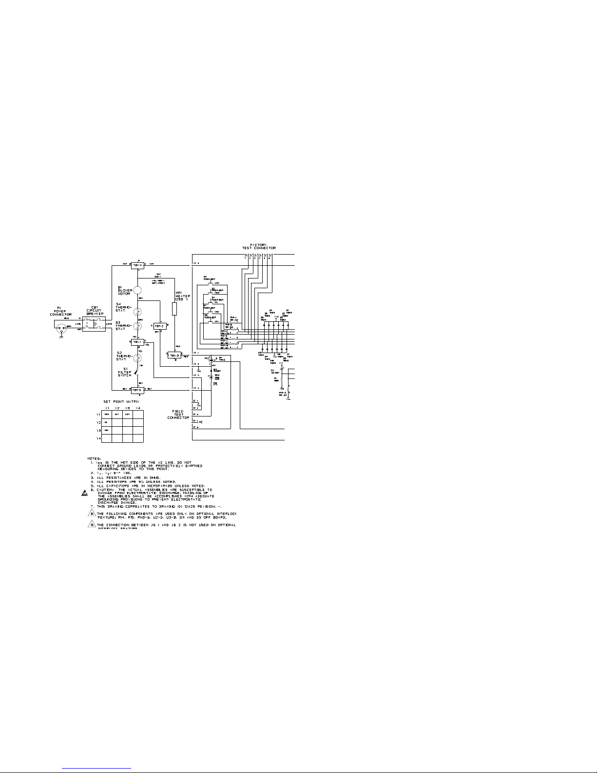
14. Reconnect both wires. Refer to TB1
designators in the schematic (figure 13) and
terminal block wiring designators in figure
11. Install cable ties.
15. Reinstall the blower wheel, making sure
there is 0.10" (2.5 mm) clearance between
the wheel and the blower inlet ring (see
fig. 9). NOTE: the hex screw must be
aligned with the flat on the motor shaft.
16. Place the filter inlet plate back on top of the
scroll. Secure the ten screws.
17. Replace the terminal block. Reconnect the
ground wire to the backing plate; make sure
the lock washer is reinstalled.
18. Replace the HEPA filter. Secure it with the
filter retainer and nut.
19. Perform the FUNCTIONAL CHECK AND
SAFETY INSPECTION (section 7, pp. 8-15).
10.0 Repair Procedures
Use only Gaymar replacement parts as
identified in the parts lists (pp. 24-27).
Useofsubstitutepartscouldresultin
power unit malfunction or patient injury.
To identify replacement parts, refer to figures
9-11 (pp. 24-27). To order replacement parts,
contact Gaymar's Export Department:
Export Telephone: (716) 662-8636
Fax: (716) 662-0730
10.1 Replacing the Patient Limit
Thermostat(s) (S2 & S3)
To replace either thermostat (item 18, fig. 11):
1. UnplugthePowerUnit.
2. Remove the six screws securing the
enclosure. Open the enclosure.
3. Carefully unplug the terminals from the
thermostat.
4. Remove the two #4 nuts from the
thermostat.
5. Replace the thermostat. Reinstall the nuts.
6. Carefully replace the terminals.
7. Perform the FUNCTIONAL CHECK AND
SAFETY INSPECTION (section 7, pp. 8-15).
10.2 Replacing the Heater
To replace the heater (item 3, fig. 9):
1. UnplugthePowerUnit.
2. Remove the six screws securing the
enclosure. Open the enclosure.
3. Remove the filter retainer and nut. Remove
Section 10 - Repair Procedures
WARNING
21

Section7-FunctionalCheckandSafetyInspection(cont’d)
7.3 Power Switch
Check the power switch light:
1. Plug in the Power Unit. Turn the power
switch on.
2. Verify that the power switch is lit.
3. Verify the Power Unit starts in the MED
(100°F, 38°C) heat setting.
7.4 Temperature Settings Switches
Examine the overall condition of the control panel:
1. Select each of the four temperature settings.
Verify that the appropriate indicator for each
lights.
7.5 Thermostat and REMOVE FROM
USEAlert
Test the Patient Limit Thermostats and REMOVE
FROM USE Alert.
The following procedure describes two different
approaches for measuring the trip points
(actuation temperatures) of the Power Unit's
patient limit thermostats. There are two patient
limit thermostats (item 18, fig. 11, p. 26) within
the Power Unit and each must be tested. The
Test Tool helps simplify these tests. Steps 1 to 20
(pp. 9-11) should be followed when a Test Tool is
available. For those facilities not having access to
a Test Tool, follow steps 21 to 50 (pp. 12-13).
NOTE: A third thermostat, the heater overtemp
thermostat (item 29, fig. 11, p. 26), is provided
to protect internal components in the event of
a motor blockage or failure. It does not need to
be function tested.
7.5.1 Test Tool Procedure (steps 1
to 20) [see fig. 10, p. 25, for Test Tool
part number]
1. UnplugthePowerUnit.
AlwaysunplugthePowerUnit
before attaching or removing
the Test Tool and when resetting
thermostats. Failure to unplug
thePowerUnitcouldresultin
electricalshockandcausedeath
or serious injury.
2. Remove the six screws on the back of the
unit. Carefully separate the two halves of the
enclosure.
3. Connect the Test Tool (fig. 5) to the 5-pin
field test connector on back of the PC board
and route the Test Tool cable out through
the opening in the bottom of the unit (see
fig. 10, p. 25). Close the two halves of the
enclosure and temporarily secure it closed
with adhesive (duct) tape. Plug in the power
unit.
9
Figure 5 - Test Tool* (P/N 08606000)
(for schematic, see figure 12, p. 27)
HEAT
S3S2
OVERTEMP
THERMOSTAT
BYPASS
WARNING
Section 9 - Troubleshooting (cont'd)
Figure 8 - Troubleshooting Chart - NO AIR FLOW
20
NO AIR FLOW
ENSUREUNIT IS
PLUGGED IN
UNPLUG UNIT; CHECK
CIRCUIT BREAKER
REPAIR/R EPLACE
IS
RFU LIT? CALL TECHSERVICE
UNPLUG
UNIT AND
OPENIT
REINSTALL
FILT ER
IS S2
OR S3
TRIPPED?
RESET
S2, S3
IS RT1
THERMISTOR ASSY
CONNE CTED?
PERFORM FUNCTION CHECK--
POSSIBLE CAUSES:
1. TOOHIGH STORAGETEMP
2. UNIT OUT OF CAL.
3. LOWSPEC ON S2, S3
PERFORM
FUNCTIONAL
CHECK
DOESRFU
REOCCUR?
POSSIB LE CONTROLLER
FAILURE;CALLTECH
SERVICE
RUN UNIT IN LOW
(90°F, 32°C)SETTING
FOR10 MI NUTES
S4HAS
TRIPPED
RESET S4
IS THERE A
BLOCKED,BENT,
OR MISALIGNED
BLOWERWHEEL?
POWERUP
UNIT.
AIRFLOW?
REPAIR/R EPLACE
MO TOR
NO
YES
NO
YES
IS CIRCUIT
BREAKERLIT?
IS FILT ER
INSTALLE D
CORRECTLY ?
REMO VE BLOCKAGE;
REPLACE/AL IGN
BLOWERWHEEL
RECONNECT RT1
THERMISTOR
ASSEMB LY
YES
YES
NO
YES
NO
YES
NO
YES
NO
NO
PERFORM
FUNCTIONAL
CHECK
NO
YES
SYMP TOM:

10
Section7-FunctionalCheckandSafetyInspection(cont’d)
Figure 6 - Temperature sensor location
Figure 6A - Hose detail, showing sensor location Figure 6B - Test setup
4. Set the two Test Tool toggle switches as
follows:
•THERMOSTAT BYPASS -- place in
center position;
•HEAT/OVERTEMP -- place in HEAT
position.
5. Locate the air temperature sensor at the
center of the end of the hose (fig. 6A).
Secure the sensor with adhesive tape. Verify
that the sensor is located at the center of
the hose.
6. Connect the hose to a Quilt (fig. 6B).
7. Turn the Power Unit on. Select the
HIGH (110°F, 43°C) setting.
8. Run the Power Unit for 5 to 10 minutes at the
HIGH (110°F, 43°C) setting. The temperature
will oscillate. During this time interval,
familiarize yourself with the following steps 9
through 14. Have a stopwatch ready.
9. Place the HEAT/OVERTEMP switch to
OVERTEMP. The temperature should start to
increase. When the air temperature reaches
119°F (48°C), start the stopwatch.
10. Allow the Power Unit to heat until either the
S2 or S3 Test Tool thermostat indicator is
lit. Stop the stopwatch and note the highest
temperature displayed. This is the upper
limit temperature for one of the thermostats.
Record the time and temperature on the
INSPECTION FORM.
Verify that the REMOVE FROM USE light is lit.
NOTE: It is acceptable if both thermostats
trip simultaneously, in which case the
S2 and S3 indicators will both be off. If
this occurs, record the elapsed time and
temperature. Verify that the REMOVE FROM
USE indicator is lit. Verify that both the
S2 and S3 indicators light by toggling the
THERMOSTAT BYPASS switch from the S2
to S3 position. (If both thermostats have
tripped, skip steps 11-14 and proceed to
step 15.)
11. Switch the Test Tool THERMOSTAT BYPASS to
whichever thermostat (S2 or S3) is lit. This
will short out the thermostat which opened
first so that the second thermostat can be
tested.
Switch the Test Tool from OVERTEMP to HEAT
to allow the Power Unit to return to normal
operating temperature before testing the
second thermostat.
12. Run the Power Unit again for 5 to 10 minutes
in the HIGH (110°F, 43°C) setting. The
temperature will oscillate. Have a stopwatch
ready.
13. Place the OVERTEMP/HEAT switch to
OVERTEMP. The temperature should start to
increase. When the air temperature reaches
119°F (48°C), start the stopwatch.
14. Continue to monitor the Test Tool until the
second thermostat indicator is lit. Stop the
stopwatch and note the highest temperature
displayed. This is the upper limit temperature
for the other thermostat. Record the time and
temperature on the INSPECTION FORM 19
Section 9 - Troubleshooting
Figure 7 - Troubleshooting Chart - NO HEAT
Always perform the FUNCTIONAL CHECK
AND SAFETY INSPECTION after making
repairs and before returning the Power
Unit to patient use. Failure to perform
the FUNCTIONAL CHECK AND SAFETY
INSPECTION could result in patient injury.
WARNING
In addition to the following troubleshooting
charts, refer to PREVENTIVE MAINTENANCE
(section 6, p. 7) and REPAIR PROCEDURES
(section 10, pp. 21-23).
NO HEAT
DO ES
QUILT
INFLAT E?
GO TO NO AIRFLOW
SYMP TOM
PRESS
EACH SETTING
BUTTON. DOES
CORRESPONDING
LED LIGHT?
CALL TECHNICAL
SERVI CE
UNPLUG UNI T;
ME ASURE HE AT ER
RESISTAN CE
IS
HEAT ER
RESISTAN CE
BETWEEN10. 0
AND 12.5
OHMS ?
REPLACE HEAT ER
UNPLUG RT1
THERMISTOR
ASSY. TURN
POWER ON.
DO ES
UNIT HEAT ?
SUSPECT PC
BOAR D; CONTACT
TECHNICAL SERVI CE
REPLACE RT1
THERMISTOR ASSY
SYMP TOM:
NO
YES
NO
YES
NO
YES
NO
YES
Quilt series
TC1050, TC1050N
TC2050, TC2050N
TC2052, TC2052N
TC2054, TC2054N
TC2060
TC2061

(table 2, pp. 16-18). Plot these values on table
2, page 18.
Verify that the REMOVE FROM USE light is lit.
15. Thermostat trip acceptance
Both thermostats must trip within the
acceptance window (see table 2, p. 18).
If this condition is not met, do not put the
Power Unit in service.
16. Unplugthepowerunit. Open the enclosure to
allow the Power Unit to cool for 5-10 minutes.
17. Locate the two patient limit thermostats (item
18, fig. 11, p. 26). Reset S2 by gently pressing
the center reset button.
Use care when resetting the
thermostats. Excessive force (force
greater than 5 pounds) can damage
the overtemp protection device
and/or inadvertently alter the trip
temperature of the device.
NOTE: Use care when resetting the
thermostats since the power terminals
are delicate. Avoid flexing the terminals.
Thermostats with loose terminals should be
replaced and retested.
18. Press the center reset button of S3. Verify it
has reset (indicated by an audible "click" and
tactile feedback). If it "clicks", proceed to step
19.
If you don't hear a "click", then what was
assumed to be the patient limit thermostat
S3 tripping was actually the heater overtemp
thermostat S4 in the same circuit. This will
rarely occur. If it has occurred, proceed as
follows:
a. Remove the filter retainer and nut.
Remove the filter. Jumper out the S4
thermostat. Replace the filter, filter
retainer and nut.
b. Run the Power Unit for 5 to 10 minutes
in the HIGH (110°F, 43°C) setting.
c. Bypass S2 by placing the THERMOSTAT
BYPASS switch in the S2 position.
Place the HEAT/OVERTEMP Switch
to OVERTEMP. Allow the Power Unit
to operate. When the air temperature
reaches 119°F (48°C), start the
stopwatch.
d. Allow the Power Unit to heat until the
S3 thermostat indicator is lit. Stop
the stopwatch and note the highest
temperature displayed. This is the
upper limit temperature for the S3
thermostat. Record the elapsed time
and temperature.
e. Verify that the REMOVE FROM USE
light is lit.
f. The S3 thermostat must trip within
the acceptance window (see table 2,
p. 18). If this condition is not met, do
not put the Power Unit in service.
g. UnplugthePowerUnit.
h. Open the enclosure and allow the
Power Unit to cool for 5-10 minutes.
i. Remove the filter retainer and nut.
Remove the filter. Remove the jumper
from the S4 thermostat. Press the
S4 reset button and insure it is reset.
Replace the filter, filter retainer, and
nut.
j. Reset both the S3 and S2
thermostats by pressing their center
reset buttons. (The S2 thermostat
may have retripped.)
19. Remove the Test Tool.
After performing the preceding test
procedure, verify that the Test Tool
and all jumpers have been removed
before returning the Power Unit to
patient use. Failure to do so may
result in death, serious injury, or
equipment malfunction.
20. Proceed to the FILTER SWITCH TEST
(section 7.6, p. 14).
Section7-FunctionalCheckandSafetyInspection(cont’d)
11
WARNING
WARNING
Table 2 - Functional Check / Inspection Form (p. 3)
Section 8 - Inspection Form (cont’d)
18
120
122
124
126
128
130
132
134
136
138
140
142
144
146
148
150
152
154
156
158
160
0 10 20 30 40 50 60 70 80 90 100 110 120 130 140 150 160 170 180 190
Time (Seconds)
Hose output air temperature (°F)
Fail (Thermostat trip point too high)
Fail (Thermostat trip point too low)
PASS (Safe range)

7.5.2 ALTERNATETestJumper
Procedure (steps 21 to 50)
21. UnplugthePowerUnit.
AlwaysunplugthePowerUnit
before attaching or removing
jumpers and when resetting
thermostats. Failure to unplug
thePowerUnitcouldresultin
electricalshockandcausedeath
or serious injury.
22. There are two patient limit thermostats within
the Power Unit and each must be tested. One
16 gauge insulated stranded wire jumper
with alligator clips will be required. To help
remember to remove the test jumper, label
a LARGE, distinctive tag “REMOVE AFTER
TEST” and tie the tag to the jumper.
Remove the six screws on the back of the
unit. Install a jumper across thermostat S3
(item 18, fig. 11, p. 26). Temporarily secure
the two halves of the enclosure together with
adhesive (duct) tape.
23. Locate the air temperature sensor at the
center of the end of the hose (fig. 6A, p. 10).
Secure the sensor with adhesive tape. Verify
that the sensor is located at the center of
the hose.
24. Connect the hose to a Quilt (fig. 6B, p. 10).
25. Plug in the Power Unit and turn it on.
Select the HIGH (110°F, 43°C) setting.
Run the Power Unit for 5 to 10 minutes.
The temperature will oscillate. During this
time interval, familiarize yourself with the
following steps 26 through 31, so that the
procedure can be accomplished quickly,
without letting the Power Unit cool.
NOTE: Perform the following steps 26
through 31 as quickly as possible, to
prevent the Power Unit from cooling
down:
26. UnplugthePowerUnit. Carefully separate
the enclosure slightly.
27. Unplug the thermistor (item 13, fig. 10, p.
25) from the back of the control board.
NOTE: The power resistor on the back side
of the PC board may be hot to touch.
28. Put the enclosure back together and secure
it with adhesive (duct) tape.
29. Plug in the Power Unit and turn it on. Leave
unit in MED (100°F, 38°C) temperature
setting. Have a stopwatch ready.
NOTE: Do not set the TEMPERATURE
SETTINGS switch to MIN (fan only) since
this setting disables the heater.
30. The temperature should increase. When the
air temperature reaches 119°F (48°C), start
the stopwatch. The Power Unit will heat until
the S2 thermostat trips. When this happens,
the blower and heater will shut off. Stop the
stopwatch and note the highest temperature
displayed. This is the upper limit temperature
for thermostat S2. Record the time and
temperature on the INSPECTION FORM (table
2, pp. 16-17).
31. Verify that the REMOVE FROM USE light is lit.
32. UnplugthePowerUnit.
33. Open the enclosure and allow the Power Unit
to cool for 5-10 minutes.
34. Locate the two patient limit thermostats
(item 18, fig. 11, p. 26). Gently press the
reset button in the center of each thermostat.
Move the jumper across thermostat S2.
Use care when resetting the thermostats.
Excessive force (force greater than
5 pounds) can damage the overtemp
protection device and/or inadvertently
alter the trip temperature of the device.
Section7-FunctionalCheckandSafetyInspection(cont’d)
12
WARNING
WARNING
Table 2 - Functional Check / Inspection Form (p. 2)
17
Section 8 - Inspection Form (cont'd)
TC3249 Power Unit Functional Check & Safety Inspection Form
Location __________________________________________________________ Initials ____________________ Date ___________________________
Hour timer (total hours) _____________________ Replaced HEPA Filter Yes _________ No __________ Serial Number __________________________
Procedure (s) Done?
(check)
Action Results **
(circle selection)
7.5.2
Thermostat* and REMOVE FROM USE alert
(ALTERNATE TEST
JUMPER PROCEDURE)
(continued from other side)
37. Plug in Power Unit. Turn unit on.
38. Run the Power Unit for 5-10 minutes in the HIGH (110ºF, 43ºC) setting to stabalize.
39. Unplug Power Unit. Separate the enclosure slightly.
40. Unplug the thermistor from the control board.
41. Tape the enclosure closed.
42. Plug in and turn on Power Unit. Leave in MED (100ºF, 38ºC) setting.
43. Start stopwatch at 119ºF (48ºC). Stop stopwatch when blower/heater shut off. Note time/temperature.
Record results. _____________seconds _______________ºF _________________ºC
44. Verify REMOVE FROM USE indicator lights. Pass Fail
45. Unplug Power Unit.
46. Open enclosure. Allow Power Unit to cool for 5-10 minutes.
47. Verify that the time/temperature values in steps 30 and 43 for both thermostats fall within the acceptance
window on page 3 of the INSPECTION FORM.
Pass Fail
48. Remove the jumper(s) from the patient limit thermostat and heater overtemp thermostat.
49. Reconnect the thermistor to the control board.
50. Reset the thermostats by pressing center reset buttons.
7.6 Filter replacement and lter switch test
1. Unplug Power Unit. Separate enclosure halves.
2. Remove lter retainer and nut. Remove lter.
3. Tape the enclosure closed.
4. Plug in Power Unit. Verify the blower does not turn on. Pass Fail
Verify the REMOVE FROM USE indicator light. Pass Fail
5. Unplug the Power Unit. Separate enclosure. Plug in Power Unit, turn it on and read hour timer.
Record total running hours of new lter label on INSPECTION FORM.
6. Unplug Power Unit. Install new lter if necessary. Record hour timer reading onto new lter label. Replace lter retainer and nut.
7. Close enclosure. Reattach screws.
7.7 Quilt Temperature
1. Prepare test setup. Mount air temperature sensor at the center of the end of the hose. Plug in Power Unit.
2. Turn on Power Unit. Set HEAT SETTINGS to LOW. Run Power Unit for 5 minutes. Note 2 highest and 2 low-
est temperatures. Average the 4 readings. Record value: _______ºF (_________ºC) [Average of 90ºF (32ºC)
values must be between 87ºF and 93ºF (30.6ºC and 33.9ºC)] Pass Fail
3. Repeat step 2 for MED setting. Record value: ___________ºF (__________ºC) [Average of 100ºF (38ºC)
values must be between 97ºF and 103ºF (36.1ºC and 39.4ºC0]
Pass Fail
4. Repeat step 2 for HIGH setting. Record value: ____________ºF (__________ºC) [Average of 110ºF (43ºC)
values must be between 107ºF and 113ºF (41.7ºC and 45.0ºC)
Pass Fail
5. Unplug the Power Unit.
7.8 Ground resistance 1. Unplug the Power Unit. Measure and record ground resistance: ____________ohms [Ground resistance must
be less than 0.5 ohms]
Pass Fail
1. Measure current leakage at the following settings:
NEUTRAL LINE LINE POLARITY VALUE
Open Normal
Open Reverse
Closed Normal
Closed Reverse
2. Verify current leakage does not exceed 100µA for all above conditions. Pass Fail
* If both thermostats trip simutaneously (i.e. at the same time and temperature), record the same results in 14 as in 10, and in 43 as in 30.
** Circling "Fail" indicates service or repair is required. Contact your local dealer for assistance.

NOTE: If both thermostats reset, both
thermostats have tripped. This is
acceptable.
NOTE: Use care when resetting the
thermostats since the power terminals
are delicate. Avoid flexing the terminals.
Thermostats with loose terminals should
be replaced and retested. Be certain the
thermostats have cooled for 5-10 minutes
before resetting.
NOTE: If thermostat S2 does not reset,
the heater overtemp thermostat has
tripped. In the unlikely event that this has
occurred, perform the following:
a) remove the filter retainer and nut;
b) remove the filter;
c) jumper the S4 heater overtemp
thermostat; and
d) replace the filter, filter retainer, and
nut. Return to step 25.
35. Reconnect the thermistor to the control
board.
36. Put the enclosure back together and secure
it with tape.
37. Plug in the Power Unit. Turn it on.
38. Run the Power Unit for 5-10 minutes in the
HIGH (110°F, 43°C) setting to stabilize the
system temperature.
NOTE: Perform the following steps 39 through
44 as quickly as possible, to prevent the Power
Unit from cooling down:
39. UnplugthePowerUnit. Carefully separate
the enclosure slightly.
40. Unplug the thermistor (item 13, fig. 10, p.
25) from the back of the control board.
41. Put the enclosure back together and secure
it with tape.
42. Plug in the Power Unit and turn it on. Leave
unit in MED (100°F, 38°C) temperature
setting. Have a stopwatch ready.
NOTE: Do not set the TEMPERATURE
SETTINGS switch to MIN (fan only) since
this setting disables the heater.
43. The temperature should start to increase.
When the air temperature reaches 119°F
(48°C), start the stopwatch. Allow the Power
Unit to heat until thermostat S3 trips. Stop the
stopwatch and note the highest temperature
displayed. This is the upper limit temperature
for thermostat S3. Record the time and
temperature on the INSPECTION FORM (table
2, pp. 16-18).
Plot these values on table 2, p. 18.
44. Verify that the REMOVE FROM USE light is lit.
45. UnplugthePowerUnit.
46. Open the enclosure and allow the Power Unit
to cool for 5-10 minutes.
47. Thermostat trip acceptance
Both thermostats must trip within the
acceptance window (see table 2, p. 18).
If this condition is not met, do not put the
Power Unit in service.
48. Remove the jumper from the patient limit
thermostat.
If a jumper was used on the S4 heater
overtemp thermostat, remove the filter
retainer, nut, and filter. Remove the jumper
from S4. Reset S4 (indicated by an audible
"click" and tactile feedback). Replace the filter,
filter retainer, and nut.
After performing the preceding test
procedure, verify that all test jumpers
have been removed before returning
the Power Unit to patient use.
Failure to remove test jumper(s)
may result in death, serious injury,
or equipment malfunction.
49. Reconnect the thermistor connector to the
back of the control board.
Section7-FunctionalCheckandSafetyInspection(cont’d)
13
WARNING
(continued)
Section 8 - Inspection Form
16
Table 2 - Functional Check / Inspection Form (p. 1)
TC3249 Power Unit Functional Check & Safety Inspection Form
Location __________________________________________________________ Initials ____________________ Date ___________________________
Hour timer (total hours) _____________________ Replaced HEPA Filter Yes _________ No __________ Serial Number __________________________
Procedure (s) Done?
(check)
Action Results **
(circle selection)
7.1
Enclosure
1. Unplug Power Unit. Pass Fail
2. Check enclosure for cracks. Pass Fail
3. Check screws. Pass Fail
4. Check labeling and markings. Pass Fail
5. Check/clean air vents. Pass Fail
6. Check hose assembly. Pass Fail
7.2 Plug, line cord 1. Examine Plug Pass Fail
2. Examine cord. Pass Fail
7.3 Power switch 1. Plug in Power Unit. Check that the circuit breaker lights. Pass Fail
2. Verify that Power Unit starts in MED (100ºF, 38ºC) heat setting. Pass Fail
7.4 TEMPERATURE SETTINGS switches 1. Check each temperature setting. Verify appropriate indicators light. Pass Fail
7.5.1
Thermostat* and REMOVE FROM USE alert
(TEST TOOL PROCEDURE)
1. Unplug Power Unit. Remove screws.
3. Conntect Test Tool. Tape enclosure closed. Plug in Power Unit.
4. Test Tool settings: THERMOSTAT BYPASS--place in center position.
HEAT/OVERTEMP--place in Heat position.
5. Prepare test setup. Mount air temperature sensor at the center of the end of the hose. Connect to quilt.
7. Turn Power Unit on. Select HIGH (110ºF, 43ºC) setting.
8. Run Power Unit for 5-10 minutes at HIGH (110ºF, 43ºC setting to stabalize.
9. Place Test Tool to OVERTEMP. Start stopwatch at 119ºF (46ºC).
10. Stop stopwatch when S2/S3 indicator on Test Tool lights. Note time/temperature
Record results, _______________seconds ________________ºF (_____________ºC)
Verify that REMOVE FROM USE indicator lights. Pass Fail
11. Bypass thermostat. Switch Test Tool from OVERTEMP to HEAT.
12. Run Power Unit for 5-10 minutes at HIGH (110ºF, 43ºC) setting to stabalize.
13. Place Test Tool to OVERTEMP. Start stopwatch at 119ºF (48ºC)
14. Stop stopwatch when S2/S3 indicator on Test Tool lights. Note time/temperature.
Record results. _______________seconds ________________ºF (_____________ºC)
Verify that REMOVE FROM USE indicator lights. Pass Fail
15. Verify that6 the time/temperature values in steps 10 and 14 for both thermostats fall within the acceptable
window on page 3 of the INSPECTION FORM.
Pass Fail
16. Turn off Power Unit. Open enclosure. Let Power Unit cool for 5-10 minutes.
17. Reset S2 patient limit thermostat.
18. Reset S3 patient limit thermostat. If a click is hear, proceed to step 19. If click is not heard, perform
steps 18a throgh 18j.
19. Remove Test Tool.
20. Proceed to 7.6, FILTER SWITCH TEST.
7.5.2 Thermostat* and REMOVE FROM USE alert
(ALTERNATE TEST JUMPER
PROCEDURE) (continued on
ther side)
21. Unplug Power Unit. Remove screws. Install jumper across thermostat S3. Tape enclosure closed.
23. Prepare test setup. Mount air temperature sensor at the center of the end of the hose. Connect to quilt.
25. Turn Power Unit on. Select HIGH (110ºF, 43ºC) setting. Run Power Unit for 5-10 minutes at HIGH (110ºF, 43ºC)setting to stabalize.
Label jumper 'REMOVE AFTER TEST.
26. Unplug Power Unit. Separate the enclosure slightly.
27. Unplug the thermistor from the control board.
28. Tape enclosure closed.
29. Plug in and turn on Power Unit. Leave in MED (100ºF, 38ºC) setting.
30. Start stopwatch at 119ºF (48ºC). Stop stopwatch when blower/heater shuts off. Note time/temperature. Record results.
______________seconds _____________ºF (______________ºC)
31. Verify REMOVE FROM USE indicator lights. Pass Fail
32. Unplug the Power Unit.
33. Open enclosure. Allow Power Unit to cool for 5-10 minutes.
34. Reset thermostat(s). Move jumper to thermostat S2.
35. Reconnect the thermistor to the control board.
36. Tape Enclosure closed.
* If both thermostats trip simutaneously (i.e. at the same time and temperature), record the same results in 14 as in 10, and in 43 as in 30.
** Circling "Fail" indicates service or repair is required. Contact your local dealer for assistance.

6. UnplugthePowerUnit. Install filter. (Install
new filter every 1000 operating hours or 12
months, whichever occurs first.) Replace
the filter only with the Gaymar P/N listed
(see parts list, fig. 9, p. 24). Record the
hour timer reading onto the new filter label.
Reattach filter retainer and nut.
The HEPA filter must be seated
properly. Failure to install the
filter correctly will prevent it from
functioning properly, and could
allow unfiltered air to reach the
patient and cause injury.
7. Replace the six screws holding the enclosure
together.
7.7 Quilt Temperature
Verify temperature output at each heat setting:
1. Prepare the Power Unit test setup, if it has
not been previously prepared:
a. Locate the air temperature sensor at
the center of the end of the hose (fig.
6A, p. 10). Secure the sensor with
adhesive tape. Verify that the sensor
is located at the center of the hose.
b. Connect the hose to a Quilt (fig. 6B,
p. 10).
c. Plug in the Power Unit and turn it on.
2. Set the TEMPERATURE SETTINGS switch
to LOW. Run the Power Unit for 5 minutes.
After 5 minutes, note the two highest and
two lowest temperature readings. Record the
average of these four temperatures on the
INSPECTION FORM (table 2, pp. 16-18).
Allowable LOW temperature:
87°F to 93°F average
(30.6°C to 33.9°C)
50. Reset the thermostats by gently pressing the
center reset buttons.
Use care when resetting the
thermostats. Excessive force
(force greater than 5 pounds) can
damage the overtemp protection
device and/or inadvertently alter
the trip temperature of the device.
NOTE: Use care when resetting the
thermostats since the power terminals
are delicate. Avoid flexing the terminals.
Thermostats with loose terminals should
be replaced and retested.
7.6 Filter Replacement and Filter
Switch Test (every 12 months or 1000
operating hours, whichever occurs
first)
1. UnplugthePowerUnit. Separate the two
halves of the enclosure. Lay the Power Unit
on its back.
2. Remove the filter retainer and nut. Remove
the filter.
3. Put the enclosure back together and secure
it with tape.
4. Plug in the Power Unit. Turn it on. Verify
that the blower does not start and that the
REMOVE FROM USE light is lit.
5. A timer which counts total running hours
is located inside the Power Unit for use by
service personnel. Timer readings may be
used to track HEPA filter usage intervals. To
read the hour timer:
a. UnplugthePowerUnit. Separate the
two halves of the enclosure again.
Locate the hour timer (see figure 10, p.
25). Plug in the Power Unit and turn it
on. Read the hour timer and record the
total running hours on the INSPECTION
FORM.
b. Turn the Power Unit off.
Section7-FunctionalCheckandSafetyInspection(cont’d)
14
WARNING
CAUTION
3. Repeat step 2 for MED setting. Average
temperatures and record.
Allowable MED temperature:
97°F to 103°F average
(36.1°C to 39.4°C)
4. Repeat step 2 for HIGH setting. Average
temperatures and record.
Allowable HIGH temperature:
107°F to 113°F average
(41.7°C to 45.0°C)
5. If the temperatures in steps 2 through 4 are
not correct, do not put the Power Unit into
service. Call your local Dealer
6. UnplugthePowerUnit.
7.8 Ground Resistance
Check grounding resistance:
1. Use a current leakage/ground resistance
tester to measure the resistance between the
grounding pin on the power entry module
and the I. V. pole clamp. An unplated area
on the underside of the I. V. pole clamp has
been provided for this test. Record the value.
2. The value should be less than 0.5 ohms.
7.9 CurrentLeakage
Measurecurrentleakage:
1. Measure and record the maximum earth
current leakage (ground open). An unplated
area on the underside of the I. V. pole clamp
has been provided if needed for this test.
Measure at all combinations of:
•line polarity
•neutral open/closed
2. The current leakage should not exceed 100
microamperes in any condition.
Section7-FunctionalCheckandSafetyInspection(cont’d)
15
7.10 CompletingtheFunctionalCheck
and Safety Inspection
If the Power Unit has passed the FUNCTIONAL
CHECK AND SAFETY INSPECTION for all
requirements of procedures 7.1 through 7.9, the
Power Unit should be considered operational and
suitable for return to service.
This completes the recommended FUNCTIONAL
CHECK AND SAFETY INSPECTION for the TC3249
series Power Unit.
Table of contents
Other Gaymar Food Warmer manuals