GBC AIO User manual

Gbc AIO
Quick Start Guide

Included items
•1x GBC AIO board
•1x Screen
•1x Optional USB socket
•4x Optional soft switches
•1x Speaker
•1x 3D printed power port cover
•1x 3D printed screen spacer
•1x 3D printed cart cover
•6x Optional 3D printed Gameboy Pocket spacers (2 extras)
•2x 3D printed LED diffuser disc (1 extra)
•1x 3D printed Button drill template
Items not included
•Gameboy Color shell
•Extra buttons for X and Y
•Optional Gameboy Pocket buttons
•Battery (102560 or similar size if you want it to fit in the battery compartment)
•SD card
•Anything not specifically stated in the “Included Items” section.

Important Notes
•Do not remove any orange Kapton tape from board/parts. Tape is adhered for electrical protection.
•Project can either use 4 Gameboy color buttons with silicone button membranes, or you can use
Gameboy pocket buttons (no letters on the buttons) by soldering the optional soft switches. (I personally
prefer the pocket buttons)
•Save and reuse all original screws.
•Any questions, please contact me at [email protected]
•Further important notes will be displayed in RED.
•Completely turn potentiometer labeled VR1 counter-clockwise, otherwise the screen may appear dimmed
or black. Adjust from there as needed.
Shell Modification
Back shell
1. Remove back metal plate.
2. Remove the battery compartment. Leave the screw holes on bottom and the lip around the edge that
catches the compartment door.
3. Clip off the tab located near the headphone jack, below the battery compartment. Clipping it off flush
should be enough but depending on the case, you may need to trim the area down slightly more if it
obstructs the headphone jack.
4. Square off the volume port hole by cutting back the sides until it reaches the edges. This will widen the
port hole to accommodate the volume wheel.
5. (Optional) Remove the plastic tab near the top so that the area is flat and flush with the rest of the case. If
you are not installing the USB port, this step is not necessary.
6. Install 3d printed cart air vent using the screw posts and screws originally used for the metal plate.

Front Shell
1. Use the provided drill template to create pilot holes for the X and Y buttons. Finish the holes with a
step drill bit. Test by placing the buttons inside the hole and SLOWLY open it more little by little until
the fit is snug. The tighter the fit, the less likely you will drill into the Nintendo logo.
2. (Optional) If you are using Gameboy pocket buttons, you will need to remove the button wells
around the A and B buttons. Ensure the area is flush after removing. If using a clear case, this will
likely cause stress damage visible from the outside if done roughly. You can use a QUICK pass-over
with a heat gun to make the stress fractures less noticeable. Clip off 4 3D printed button spacers and
insert them into the pocket buttons. There are 2 extra spacers in case you damage/lose others. STL
files can be found in the downloads tab of the GBC AIO page.
3. Clip off left headphone tab. If you are using a clear case and want to avoid damaged plastic being
visible from the outside, only clip off the tab half way (height) to make enough room for the
headphone jack.
4. Completely remove both sides of the screen surround. This area his hidden on the outside by the
screen protector so don’t worry too much about scratching or damaging on a clear case.
5. You may need to slightly cut back/flatten the sides of the left screw posts if the screen doesn’t fit
correctly
6. Cut ½ of the LED tube (left side facing screen) to make room for the screen. Leave the right half of
the circumference. This led tube will help stabilize the screen horizontally so cut less, test the screen
fit, and go back and do a little more until the screen slides in firmly. If you cut too much, it’s not the
end of the world, the screw posts will still do a good job stabilizing the screen. The cut led tube edge
should align with the screw posts.
7. (Optional) Clip off the top right of the screen surround if you are installing the USB port and ensure
the area in front of the port is completely flush.
8. Snip the tab located at the EXT port center so that it is flush with the rest of the lip. You may need to
shave it down more if it is still blocking the charging connector.
9. Cut one of the LED diffuser discs from the strip of 2 (the second is an extra) and fit it inside the LED
tube. It should have a pressure fit but if it is loose, you can use a little hot glue.


Board Assembly
and Installation
1. (Optional) If you are using the soft switches/pocket buttons, push the buttons into the button thru-
holes of button B (do not remove tape covering buttons) and snip off the excess pin length sticking
out. Then remove the button and snip off a little more and place them back into the thru-holes to
check length. Ensure no pin sticks out pass the board as the Pi will need to sit flush over this area and
the pins cannot be allowed to touch the pi. Alternatively, you can snip off all the button pins at the
height of the raised corners.
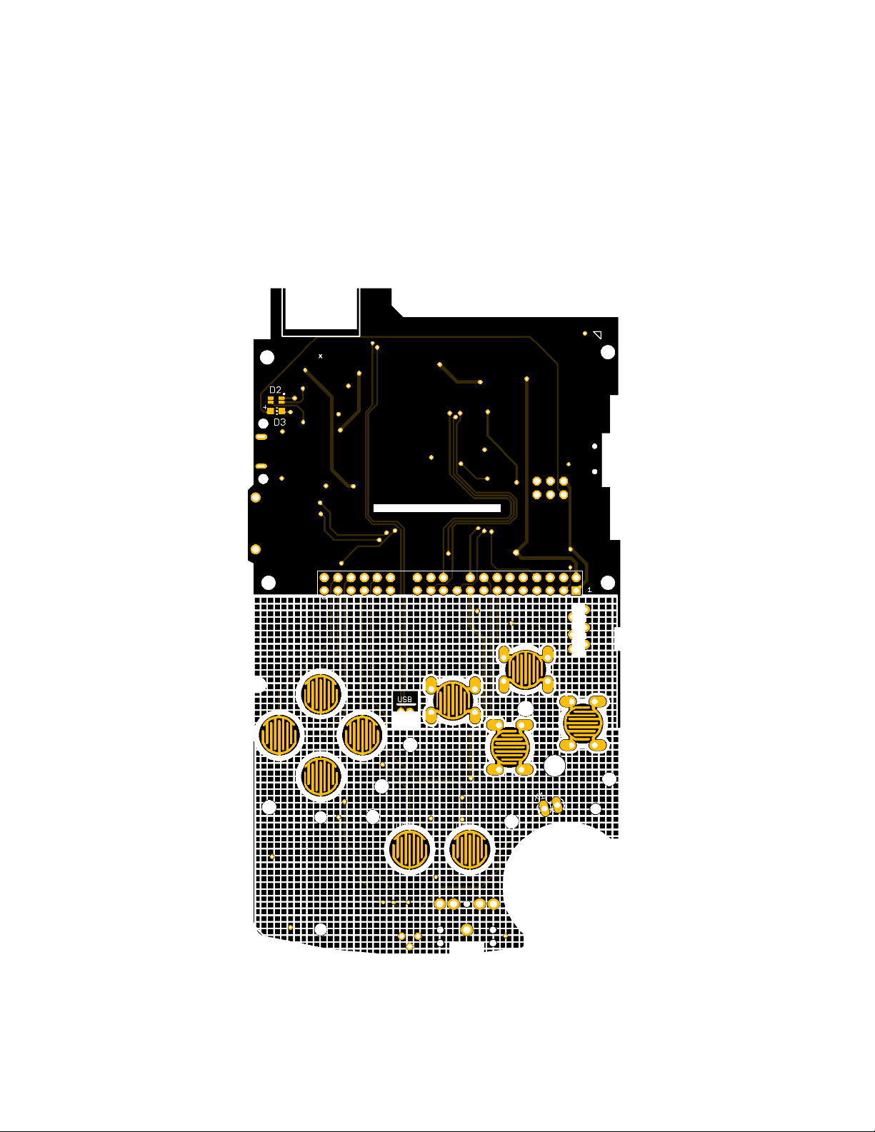
Solder the switches from the front of the board using the solder pads. Ensure that each switch is
centered as best as possible by soldering only one pin and adjusting it as needed before soldering
the other pins.
2. Use flush cutters or a dremel to remove the pi screw hole between the sd card reader and gpio.
3. Solder the pi zero to the board by aligning the pinholes on the board to the pi. Align the boards using
the USB pads as the priority, ensuring the test pads line up evenly with the castellated holes. Using a
small diameter solder that fits through the pinhole is the easiest method. Push the solder strand
through both boards, solder one side and then use your iron to break the strand and solder the other
side. Repeat for all pinholes.
4. Solder the SD pads and USB pads of the pi to the AIO board castellated pads from the front side of
AIO board. If you don’t plan to use the usb port, you don’t need to solder usb pads.
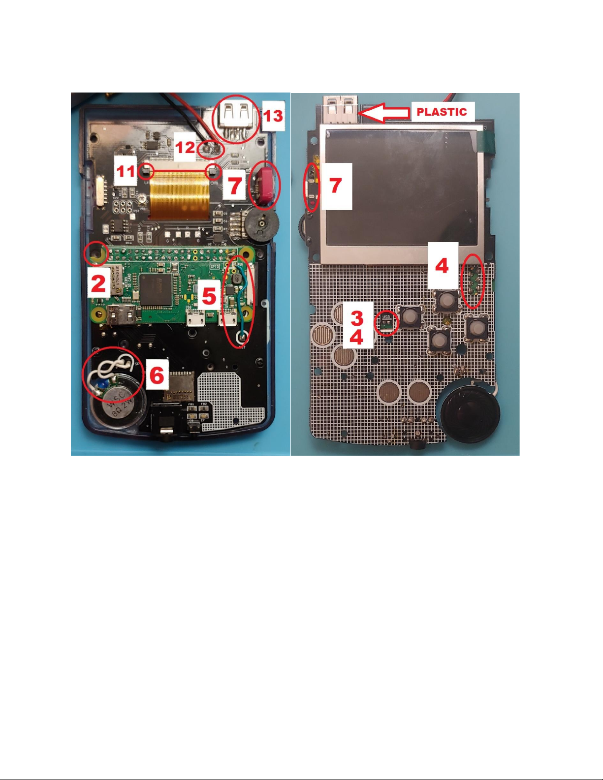
5. Solder a short jumper wire between the square RUN pin on the pi and the RST pin on the AIO board.
This wire is to hard reset the system using the switch button at the bottom of the AIO board.
6. Solder short jumper wires from the SP pins to the supplied speaker.
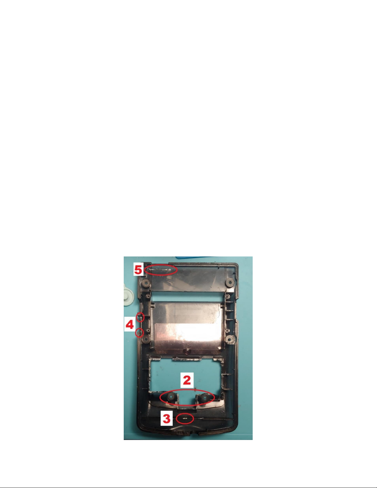
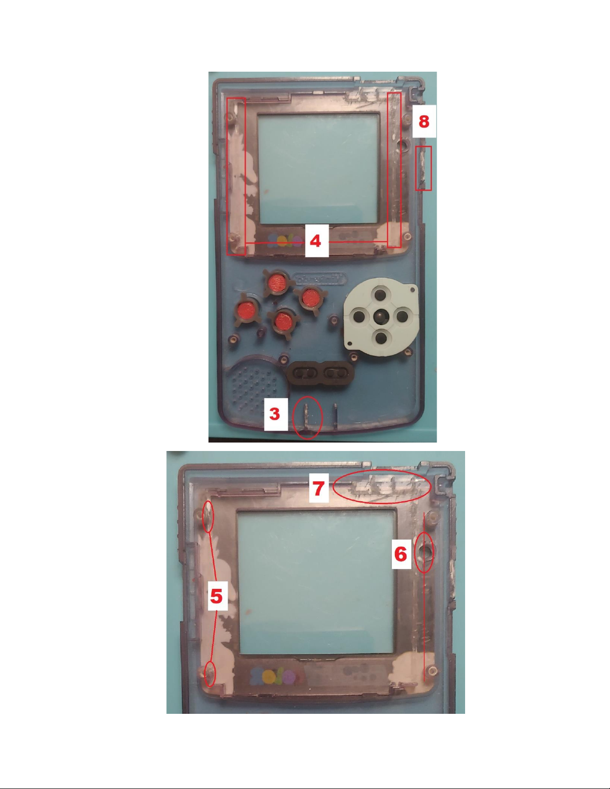
7. Install 3d printed power port cover by placing it over the charging connector, placing the peg end
towards the volume wheel and screwing in the other side.
8. Place the screen into the modified front shell and then place the 3d printed screen spacer on top of
it, with the protruding edge placed in the top left corner facing downward. The protrusion will be
wedged between the screen and the screen surround plastic, keeping the screen from moving
vertically.
9. Place the AIO board over the screen and spacer, slipping the screen ribbon cable through the slotted
hole on the aio board. Lower the speaker into its place.
10. Adjust the board so that it aligns to the screw posts best as possible. In my experience, there is a
large variation between aftermarket gbc shells so you may need to slightly shift the board around as
you screw it in to make sure its aligned right. Screw the board in using the 3 white rimmed screw
holes located at the left, center, and right at the bottom of the board.
11. Insert the screen cable fully into the screen connector on the AIO board and lock the connector in
place. Pull side tabs of connector forward to open the connector, place ribbon cable in, and then
push tabs back into place to close the connector.
12. Solder your battery to the B+ and B- pads. You will likely need to extend your cables to reach the
battery compartment.
13. (Optional) Solder the USB connector into place, plastic side facing down towards the front of the
shell. USB port is not needed and completely optional.
14. Insert the power switch cover over the switch, in the lowest position (switch is smaller than
cover so there will be slack, that’s normal). Pull the battery through the compartment. Place the
back shell over the front shell gently, adjusting the power switch and any other parts that may
be obstructing the closure. Install the rest of the shell screws.


Software
•Burn the provided SD image (located on the sales page for gbc aio) to an SD card that is atleast
8gb.
•Once the image is burned, use the retopie menu to expand the sd card memory if you used an
sd card larger than 8gb. This is important, otherwise you wont be able to use your full sd
memory.
•Use the provided wpa configuration file to setup your wifi. Type your wifi name and password in
the quotation marks (keep the quotation marks), adjust your country if you are not in the US,
and then place the text file in your boot folder from a computer. When you start up your
system, if the information you provided was correct, you should now be connected to wifi and
be able to ssh roms into your system. Check by using going to the retropie menu and clicking on
the wifi setting. If you are connected, your wifi name will be displayed. Select exit and press the
start button to go back to retropie.
•Once you are done using wifi for transferring roms, you must go back to the wifi setting in the
retropie menu and remove your wifi connection. Keeping the wifi connected will cause lag in
your games and can deplete the battery faster.
Extras
1. The SD card is accessible through the battery port. Use your thumb nail to gently pull the card
forward to remove. To avoid risk of damaging your card, do not use excessive downward force.
2. Hard reset switch is located at bottom of shell in the OEM power cable port. It is hidden behind
the port hole to avoid accidental rest. If there is a software issue preventing the board from
powering down using the switch, simply set the slide switch to off position and then use a
narrow object like a pencil to push the hard reset button.
3. Shoulder button breakout pads can be used for installing shoulder buttons. They are labeled as L
and R on board, and have a ground pad located next to each for convenience. I currently do not
have any designs for shoulder buttons so this would have to be DIY.
4. Setup digital audio control and map it to hotkeys on your system for a better audio experience.
The volume wheel may not completely cut the sound when all the way down, so digital volume
control (with the wheel all the way up) is recommended, but not necessary.
5. The USB port is 100% optional. As long as your pi zero is a W (wifi enabled), then any setup
necessary can be done purely from ssh’ing into the system from a computer.
6. The Gameboy controls can be used to navigate the system level menus. The dpad will give you
direction controls (mapped to arrow keys) and the start button will let you select (mapped to
enter key).
7. There is an optional audio gain located under the screen ribbon cable. The current gain is set to
9db. Solder the center pads together to set a gain of 12db. Solder a 100kohm resistor between
the 2 circular pads on the side for a 15db gain. You can only choose one, do not solder the
center pads and solder resistor simultaneously. Results may vary and you may need a larger
speaker to hear noticeable differences. It is recommended to keep the default settings.
8. Brightness can be adjusted by turning the small potentiometer on the back of the board. It can
only be adjusted when the back shell is off. If your screen in black, make sure the pot is turned
completely counter-clockwise
Table of contents
Other GBC Industrial Equipment manuals

GBC
GBC PIPE 8 User manual

GBC
GBC Quantum P70iX User manual

GBC
GBC USP 13 User manual

GBC
GBC 34.0136.00 1500W User manual

GBC
GBC DIGITAL FEEDER Manual

GBC
GBC CombBind C800pro User manual

GBC
GBC PIPE 8 User manual

GBC
GBC MINI AUTO COMPACT User manual

GBC
GBC Quantum P70iX User manual

GBC
GBC BOILER 1-4 K User manual
Popular Industrial Equipment manuals by other brands

Aerotech
Aerotech HIGH-POWER RMS M750W-P Assembly and operation instructions

Behncke
Behncke QWT Series Installation instruction

THORLABS
THORLABS LabView DCU2 Series Programming manual

Triminator
Triminator XL DRY quick start guide

Bosch
Bosch Rexroth SHA Series operating instructions

ABB
ABB HT611078 Operation manual