CC613_D00381_04_M_XXEN/11.2020 3
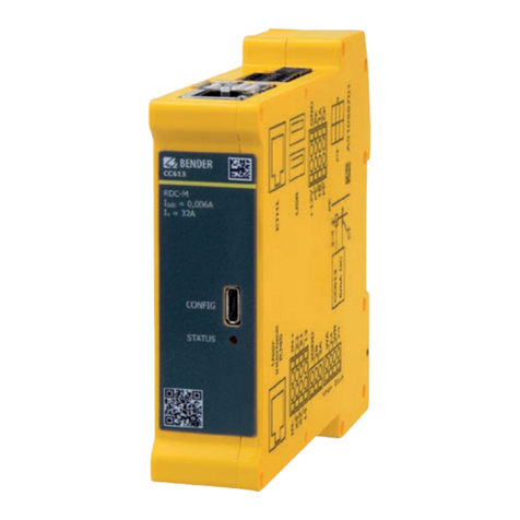
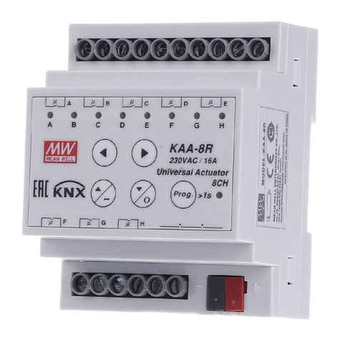
CC613 charge controller
Table of content
1 General instructions .........................................................................5
1.1 How to use this manual..............................................................................................5
1.2 Indication of important instructions and information ...................................5
1.2.1 Signs and symbols........................................................................................................5
1.3 Training courses and seminars.................................................................................5
1.4 Delivery conditions.......................................................................................................5
1.5 Inspection, transport and storage ..........................................................................6
1.6 Warranty and liability...................................................................................................6
1.7 Disposal of Bender devices........................................................................................6
1.8 Safety.................................................................................................................................6
2 Function...............................................................................................7
2.1 Intended use...................................................................................................................7
2.2 Product features (depending on the variant).....................................................7
2.3 Product description......................................................................................................8
2.4 Functional description ................................................................................................8
2.4.1 General functions..........................................................................................................8
2.4.2 Load current and cooling control
(temperature monitoring)..........................................................................................9
3 Dimensions and mounting ........................................................... 10
3.1 Dimensions................................................................................................................... 10
3.2 Mounting.......................................................................................................................10
4 Connection ....................................................................................... 11
4.1 Connection conditions............................................................................................. 11
4.2 Connection to type 1/type 2 plugs .....................................................................11
4.2.1 Connection plug connections...............................................................................11
4.2.2 Charging system with type 2 socket-outlet.....................................................12
4.2.3 Connection locking actuators ...............................................................................14
4.3 Connectivity.................................................................................................................14
4.3.1 Master/slave connection.........................................................................................15
4.3.2 USB configuration interface (CONFIG) ...............................................................15
4.3.3 Ethernet interface ......................................................................................................15
4.3.4 STATUS LED.................................................................................................................. 15
4.3.5 12 V power supply..................................................................................................... 15
4.3.6 Contactor connection...............................................................................................15
4.3.7 Weld check ...................................................................................................................16
4.3.8 Alternative connection switching contact contactor...................................16
4.3.9 PE monitoring..............................................................................................................17
4.3.10 Control Pilot (CP) and Proximity Pilot connections (PP)..............................17


