GCE EASE II User manual
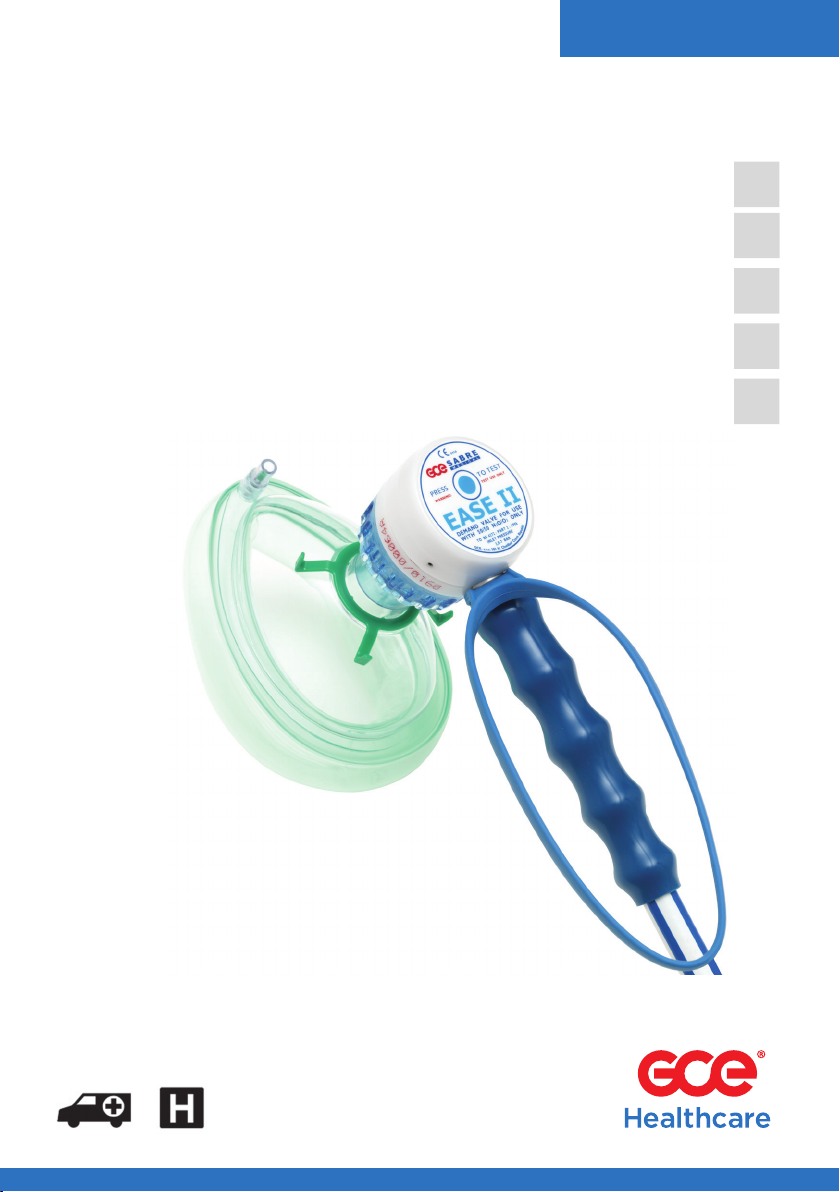
EASEII
DEMAND VALVE; INSTRUCTION FOR USE
ODBĚROVÝ VENTIL; NÁVOD K POUŽITÍ
VALVE A LA DEMANDE; MODE D’EMPLOI
DEMANDVENTIL; BRUKSANVISNING
VENTIL PO POTREBI; UPUTE ZA KORIŠTENJE UREĐAJA
GCE HEALTHCARE
EN
CS
FR
SV
HR


3/72
EN
1. FOREWORD
GCE EASE II low pressure medical demand valves are medical devices classified as class IIa
according to the Medical Device Directive 93/42/EEC. Their Compliance with essential
requirements of 93/42/EEC Medical Device Directive is based upon BS 4272:1996 standard.
2. INTENDED USE
The GCE EASE II low pressure demand valve is designed to be fitted to medical gas pipeline
systems or to quick connector outlet of medical gas regulator. EASE II demand valves are
intended to be used under supervision for the administration of a medical gas in response to the
patient´s inspiratory eort. The EASE II Demand valve is intended for use in the administration of
the following medical gases in the treatment and care of patients and is suitable for use in the
hospital or pre-hospital (emergency medical) environments:
• Oxygen O2
• Nitrous oxygen mixture O2/N2O - 50/50%
3. OPERATIONAL, TRANSPORT AND STORAGE SAFETY
REQUIREMENTS
Keep the product and its associated equipment away from:
• heat sources (fire, cigarettes,...)
• flammable materials,
• oil or grease (take a great care in the use of hand creams),
• water,
• dust.
The product and its associated equipment must be prevented from falling over.
Always maintain oxygen cleanliness standards.
Use only the product and its associated equipment in well ventilated area.
Before initial use the product shall be kept in its original packaging. GCE recommends use of
the original packaging (including internal sealing bag and caps) if the product is withdrawn from
operation (for transport and storage). Statutory laws, rules and regulations for medical gases,
accident prevention and environmental protection must be observed.
OPERATING CONDITIONS STORAGE AND TRANSPORT
CONDITIONS
MIN MAX MIN MAX
O2 -20 °C
+60°C
-30 °C +60 °C
O2/N2O +5 °C +60°C
10 % 100 % 20 % 70 %
600 mbar 1200 mbar 600 mbar 1200 mbar
ENGLISH
INSTRUCTION FOR USE: DEMAND VALVE EASE II
4/72
EN
In case of storage at a temperature below -20 °C or above 60°C do not operate the demand
valve until it has been allowed to change its temperature inside operating temperature limits.
For the demad valve intended to be used with mixture of gases O2+N2O, the lowest operat-
ing temperature is +5°C.
Do not use the device without being properly trained!
All gases under pressure can be hazardous and should be treated with caution.
Do NOT use oil or grease (unless specifically approved) on any part of an EASE II system.
Ensure hands are clean and free from oil and grease.
Keep system away from sources of ignition at all times.
Do NOT tamper with the equipment.
Do NOT try to connect an EASE II valve to terminal unit/quick connector of the incorrect gas
type.
4. PERSONNEL INSTRUCTIONS
The Medical Devices Directive 93/42/EEC states that product provider must ensure that all
personnel handling the product are provided with the operating instructions & performance
data.
Do not use the product without properly familiarization of the product and its safe operation
as defined in this Instruction for use. Ensure user is aware of particular information and knowl-
edge required for the gas in use.
5. PREPARATION FOR USE
5.1.CONNECTION OF THE HOSE TO THE GAS SOURCE
• Connect the supply hose
to the source of gas. For
more information regarding
gas - specific medical quick
connectors, see to Appendix
2.
• Regularly inspect the hose
during use to ensure that
the hose is not torn, bent,
twisted, or aected by
excessive pull.
• Regularly check the supply
of gas or the contents in the
cylinder.
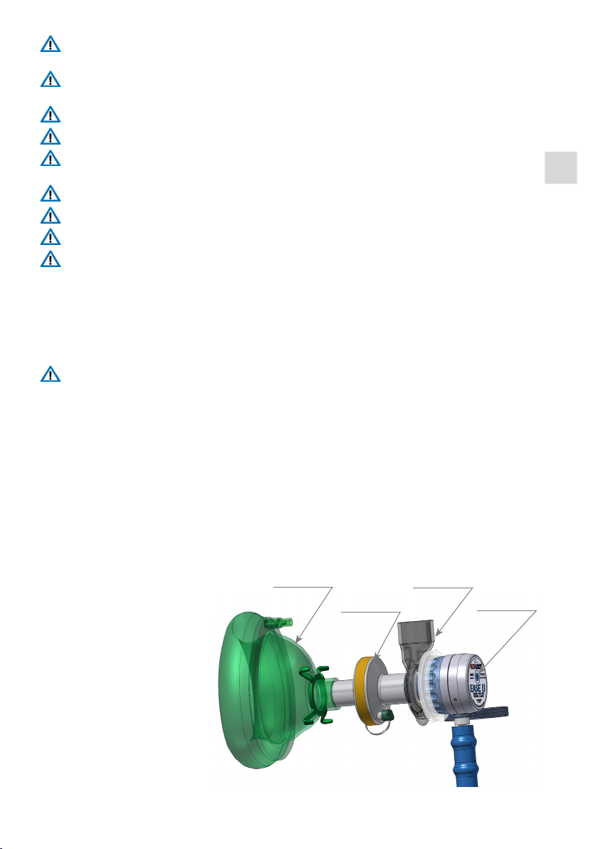
5.2.FITTING
SCAVENGING ADAPTOR
• When using the scavenging adaptor, fit it to the demand valve by pushing it over the patient
port. (see Fig. 1).
• Then connect the exhalation pipe to scavenging adaptor.
NOTE: A scavenging adaptor should be fitted when EASE II for O2/N2O is used in enclosed
spaces. Failure to fit a scavenging adapter can result in supervisory personnel becoming
drowsy.
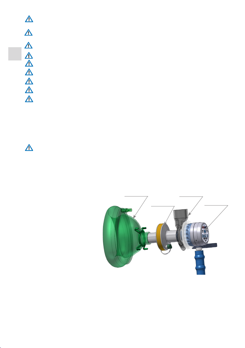
Fig. 1: Fitting scavenging adaptor, filter and mask
Test button
Scavenging
adaptor
Antibacterial
filter
Mask

5/72
EN
5.3.FITTING MASK OR MOUTHPIECE AND FILTER
Select mask or mouthpiece and filter as appropriate for the patient and fit to the demand valve
by pushing it over the 22 mm insert female tapered outlet on the patient port (see Fig. 1).
NOTE: Some patients find masks claustrophobic and may fight against the use of EASE II if
oered in this way. With such patients use of a mouthpiece is recommended.
5.4.TESTING PRIOR TO ADMINISTRATION
Units should be checked by lightly pressing the test button (see fig 1., fig.2). Gas should be
heard flowing through the mask or mouthpiece. On releasing the test button, the flow should
stop.
NOTE: If the system does not operate i.e. does not give a gas flow on depressing the test
button or the system does not stop giving flow, turn o the cylinder or disconnect from the
gas source and refer to the TROUBLESHOOTING chart in Section 9.
6. OPERATIONS
6.1.ADMINISTERING OF MEDICAL GASES
Medical gases 50/50% O2/N2O or 100 % O2should only be administered by persons trained to
do so and under qualified medical supervision.
Cylinder contents must be checked regularly during therapy and the cylinder replaced as
necessary.
1. Calmly explain to the patient purpose and operation of the demand valve. Reassure and
encourage him/her to breathe normally.
NOTE: Patients do not have to remove the mask or mouthpiece during exhalation.
2. Place the mask on the patient and support the mask over the mouth and nose, with the
patient breathing normally and not remove the mask when exhaling.
NOTE: If a mouthpiece is fitted, instruct them to hold it between their teeth, sealing on it with
their lips and to breathe through their mouth only.
3. Instruct the patient to breathe through the demand valve as required to reduce the level of
pain. (Continuous use is often unnecessary).
NOTE: Supervisory personnel can help support the mask, if should the patient is incapable
of holding it.
4. Constantly monitor the patient and the cylinder contents during administration. Check
volume of gas in the cylinder and replace the cylinder if necessary.
5. The administration of 50/50 O2/N2O may cause the patient to become drowsy. The seal
between the mouth and the demand valve will be lost and ambient air will be inhalated. The
patient will then begin to regain consciousness and an awareness of pain; and should be
encouraged to breathe the gas again.
6.2.AFTER USE
1. When treatment has been completed, close the cylinder valve and operate the test button
to de-pressurize the system or disconnect the demand valve from the wall outlet or quick
connector.
2. Clean the system as described in Section 7.

6/72
EN
7. CLEANING
De-pressurize the system and disconnect from the gas supply prior to cleaning. Refer to the
exploded view of the demand valve parts below.
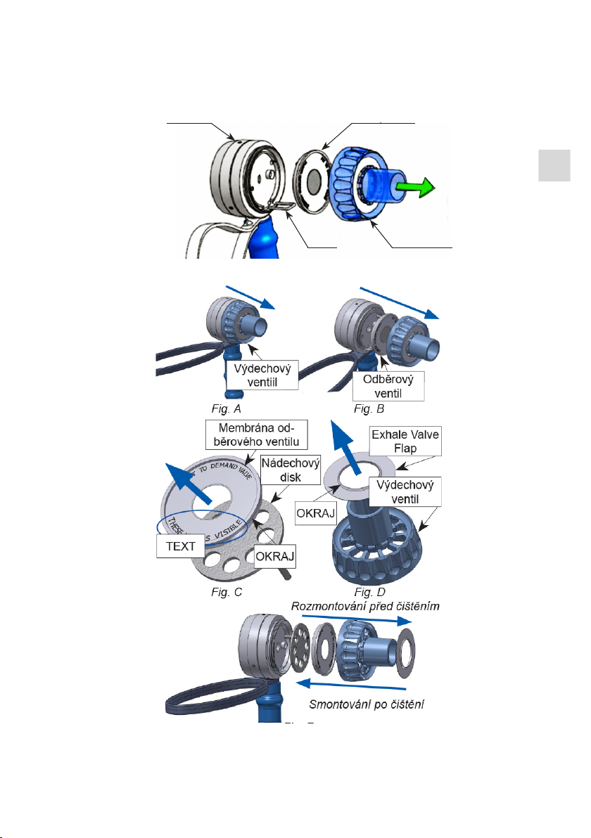
Fig. 2: Demand valve parts
U-clip Patient port
assembly
Inhalation
disc
Demand
Valve
Fig. 3: Dismantling of EASEII before cleaning
Fig. E

7/72
EN
Do not use cleaning solutions containing ammonia!
Do not expose to water or any other liquid.
Do not expose to high temperature (such as autoclave), unless it is stated otherwise.
To apply the cleaning solution do not spray it as the spray may enter into the inner parts of
demand valve and cause contamination or damage.
Do not use pressure wash as it could damage or contaminate the demand valve.
If the inner parts of the demand valve have been contaminated do not continue to use the
demand valve under any circumstances. It must be withdrawn from service.
7.1.CLEANING THE INHALATION DISC AND PATIENT PORT ASSEMBLIES
If an filter is used and bodily fluids have not contaminated the demand valve, only wiping the
demand valve with a disinfectant is necessary. Remove dirt with a soft cloth damped in oil free
soap water & rinsed with clean water. If demand valve has been contaminated by secretions,
blood, or vomit, then cleaning as outlined below is necessary.
1. Unscrew the patient port assembly from the demand valve (Fig. A) and remove the inhale
disc assembly (Fig. B).
2. Remove the silicone valve flaps from the patient port and inhale disc (see Fig.C,D). Take care
not to overstretch or damage these parts during removal.
3. If an antibacterial filter is used, cleaning is not necessary after every use. However,
recommended. If demand valve has been contaminated by blood or vomit, the cleaning is
necessary. Follow one of cleaning procedures bellow according to your preference:
a. Either wash all parts with warm water at a maximum temperature of 60°C, use an approved
disinfectant. The mechanical resistance of the components (Patient port, Inhale disc, Inhale
valve flap, Exhale valve flap), are guaranteed to 20 sterilization cycles under the cleaning
conditions mentioned below.
Example of cleaning with cold disinfectant:
Meliseptol: Remove dirt with a soft cloth damped in warm water with max. duration 30
seconds. Disinfection apply on the components (application of disinfectant for 1 minute). After
applying the disinfection, clean the components in running cold tap water. The components
shall be carefully dried with a soft non-abrasive cloth.
b. Or put the parts in an autoclave for 5 min at 134° C or for 20 min at 121° C.
After the cycle is complete, wait until parts get cool and check for damage. Assembly the
device (see section 5). The mechanical resistance of the components (Patient port, Inhale
disc, Inhale valve flap, Exhale valve flap), are guaranteed to 20 sterilization cycles under the
cleaning conditions mentioned above.
Later, the degradation of plastic substances may occur.
7.2.DISASSEMBLY OF THE DEMAND VALVE
1. Unscrew the patient port assembly from the demand valve (Fig. A) and remove the inhalation
disc assembly (Fig. B).
2. Remove the silicone valve flaps from the patient port and inhalation disc (see Fig.C,D). Take
care not to over-stretch or damage these parts during removal.
7.3.CLEANING THE DEMAND VALVE
DO NOT immerse the demand valve in disinfectant liquids.
1. Clean external surfaces of the valve with a lint-free cloth, slightly moistened in soapy water.
Dry with a lint-free cloth.
2. Disinfect the outer surface.
3. If the hose connection to the demand valve is contaminated, remove the hose from the
demand valve (see Chapter 7.4). Clean and dry the hose with a lint free cloth. Clean the hole
in the demand valve carefully with cotton moistened with clean water and disinfect.
4. If a demand valve suers internal contamination and normal cleaning is not eective, the
valve must be returned for servicing by a qualified technician.

8/72
EN
7.4.REMOVING & REFITTING THE HOSE FROM THE DEMAND VALVE
BODY
To remove the hose from the Demand Valve proceed as follows:
1. Disconnect EASE II from its gas supply and de-pressurize the system fully. If in any doubt,
contact Training and Technical Support Services at the address shown above.
2. Remove the patient port and inhalation disc assemblies. See fig 3 above.
3. Lift and remove the U-clip using a small screwdriver. See fig 2 above.
4. Pull the hose from the demand valve. Protect the hose connector from dirt and damage.
5. Reassembly is the reverse of the removal procedure. When refitting the U-clip ensure it is
fully seated.
6. Refit the patient port and inhalation disc assemblies.
7.5.CLEANING THE MASK, MOUTHPIECE, SCAVENGING ADAPTER
1. Masks for multiply use clean or sterilize according to the manufacturer’s instructions attached
to the mask. Masks for single use must be disposed after use.
2. The mouthpieces are single use only. Dispose of mouthpiece after use.
3. Scavenging adaptor can be washed in warm water (max 60°C) using approved
disinfectantwater and rinsed in clean water, or autoclaved at 121°C as preferred.
7.6.CLEANING HOSE ASSEMBLY
Hose assembly must be cleaned if contaminated or as part of regular cleaning. It is not
necessary to clean it after every use.
1. De-pressurize hose assembly and disconnect from the gas supply.
2. The external surfaces should be cleaned using a lint-free material moistened with soapy
water. Dry with a lint free material.
3. To disinfect, thoroughly wipe the outer surfaces with a disinfectant wipe.
4. Re-assemble the system and test according to the instructions in Chapter 7.7.
Please ensure that no disinfectant enters the hose, as there is risk of respiratory injuries.
7.7.REASSEMBLY OF EASEII AND TESTING AFTER CLEANING
1. Fit the hose back as described in section 7.3. if removed.
2. Place the inhalation flap back on the inhalation disc. Make sure the rim is placed over the
inhalation disk and letters “THESE WORDS VISIBLE” are up and readable - see Fig. C.
3. Place the inhalation disc assembly into the demand valve see Fig. B and D.
4. Place the exhalation flap into the patient port, make sure the rim is placed upward - see Fig.
D.
5. Screw the patient port onto the demand valve - see fig. A.
6. Test EASEII according to section 5.4. and use according to section 6.
NOTE: For cylinders with a regulator, it is recommended that the regulator be attached to the
cylinder, but with the cylinder turned OFF.
9/72
EN
8. MAINTENANCE
8.1.REGULAR CHECKS AND ROUTINE MAINTENANCE
1. T
he cylinder contents and the operation of the system must be checked regularly and prior to
use, as described in Sections 6.2.
2. Before each use, perform an audible and visual check on the hose for leaks and damage. If a
leak is detected, or if there is damage, such as cracks or abrasion in the hose outer cover the
hose must be replaced. Return the complete unit to an approved repairer for hose replacement.
3. The following components must also be checked on a regular basis for wear and tear and may
be replaced by the user as required:
• Inhalation disk
• Inhalation valve flap
• Patient port
• Exhalation valve flap
NOTE: Follow the instructions in Section 7 to change the Inhalation disc, Inhalation flap, patient
port and exhalation valve flap.
Observe the oxygen cleanliness warnings given in Section 4 when changing the cylinder seal.
All labels on the EASE II must be kept in good, legible condition by the owner and the user during
the entire product life time, replace as necessary.
All spare components must be kept in their original packaging to maintain batch / suppliers iden-
tity. All spare components must be stored in a dry, dark and clean environment by the owner/
user.
Use only original GCE components!
8.2.ANNUAL INSPECTION
EASE II must be inspected annually. No special tools or test equipment are required for the
annual inspection. The annual inspection may be carried out by the user or an approved GCE
repairer. Records of the annual inspection must be made and held for the life of the product.
See Chapter 8.3. for the annual inspection procedure and section 14 for an example of annual
inspection record sheet.
If components other than those listed in section 8.1 require replacing, the Demand Valve
complete with hose assembly must be returned to an approved GCE repairer for the work to be
carried out, as special tools and test equipment are required.
GCE approved repairers are trained by GCE to carry out servicing in accordance with the GCE
Service Manual.
A Service Manual with service and test equipment is available from GCE, s.r.o.
GCE, s.r.o. Tel : +420 569 661 111
Zizkova 381 Fax : +420 569 661 602
583 01 Chotebor http://www.gcegroup.com

10/72
EN
8.3.ANNUAL INSPECTION PROCEDURE
8.3.1.VISUAL INSPECTION
Step Procedure Comment/Action
1Depressurize and disconnect the demand
valve from the pressure supply
Use the test button on the back of the EASE
valve to depressurize the demand valve and
hose if required
2Check the demand valve serial number is
legible
If the serial number is not legible the demand
valve should be removed from service
3Check the demand valve has not exceed its 10
year life period
The first four digits of the serial number is the
year of manufacture. If the date at the time
of inspection is more than 10 years after the
manufacturing year the Demand Valve should
be removed from service and disposed of.
See 8.4.
4Check the hose has no damage to its outer
cover such as cuts, or significant abrasions.
The hose will require replacing if it has cuts, or
significant abrasions in its outer cover. Send
the demand valve to an approved GCE repairer
for hose replacement.
5Check that the hose is not kinked or miss-
shaped.
A kinked or miss-shaped hose indicates
the hose reinforcement has been damaged
and the hose should be replaced. Send the
demand valve to an approved GCE repairer for
hose assembly replacement.
6
If the hose is the type which connects to a
pipeline terminal outlet check the metal probe
connector is not damaged or worn.
A worn or damaged metal probe connector
may leak and should be replaced. Send the
demand valve to an approved GCE repairer for
hose assembly replacement.
7Check the Demand Valve body and rear cap is
not cracked or damaged.
If cracks or significant damage is evident on
the valve body or the rear cap the Demand
Valve should be withdrawn from service.
8
Check the three small grub screws securing
the Demand Valve rear cap to the main body
are in place.
If any of the grub screws are missing return the
Demand Valve to an approved GCE repairer.
9Check the label on the rear cap is in place and
in good condition
If the label needs replacing send the demand
valve to an approved GCE repairer for label
replacement.
10
Unscrew patient port assembly from main valve
body and remove exhalation valve flap from
the patient port.
See section 7 for further information on
disassembly procedure
11 Check patient port for cracks or damage. Replace patient port if damaged
12 Examine the exhalation valve flap for tears and
splits Replace exhalation valve flap if required
13 Refit exhalation valve flap to patient port.
See section 7 for further information on
refitting procedure
14
Lift inhalation disc assemble out of the Demand
Valve body. Remove inhalation valve flap from
the inhalation disc.
See section 7 for further information on
disassembly procedure
15
Examine the inhalation disc and pin. Check the
inhalation disc is flat . Check the pin is not bent
and is sitting square to the inhalation disc.
Replace inhalation disc (with pin) if required

11/72
EN
16 Examine the inhalation valve flap for tears and
splits. Replace inhalation valve flap if required
17 Refit inhalation valve flap to inhalation disc.
18
Refit inhalation disc assemble to the Demand
Valve body. Note the pin should slide easily
inside the hole in the Demand Valve body
19 Refit patient port assemble to the Demand
Valve body. Screw on hand tight only.
8.3.2.LEAK TESTING
Step Procedure Comment/Action
1Connect the demand valve to gas supply Gas will briefly flow as the Demand Valve is
connected to the gas supply, this is normal.
2Using a suitable leak detection fluid check
for leaks at:
The leak detection fluid should be compatible
with oxygen and suitable for use on plastic
components.
3The joint between the hose and hose fittings
at each end of the hose.
If a leak is found return the Demand Valve to
an approved repairer for hose replacement.
4The swivel joint between the Demand Valve
body and the hose fitting.
If a leak is found return the Demand Valve to
an approved repairer for repair.
5The connection between the hose probe
and the gas supply point.
If a leak is found here it may be due to a
worn male hose probe or a fault in the gas
supply connection. To eliminate gas supply
connection try a dierent supply point. If
leak continues hose assembly will require
replacement. Return the Demand Valve
to an approved repairer if the hose needs
replacing.
6
Unscrew the patient port assembly from
the Demand Valve body and lift out the
inhalation disc assembly.
7
While the Demand Valve is connected to
the gas supply hold the Demand Valve body
close to your ear (with outlet holes towards
your ear) and listen for leaks. No leaks
should be heard.
If a leak can be heard it indicates a fault with
either the main valve or pilot valve. Return
the Demand Valve to an approved repairer
for repair.
8Refit the inhalation disc assemble to the
Demand Valve body.
9Refit patient port assemble to the Demand
Valve body. Screw on hand tight only.
8.3.3.DEMAND VALVE OPERATION TESTING
Step Procedure Comment/Action
1Connect hose to gas supply.
Test gas may be air, nitrogen, oxygen or
N2O/O2mixture.Gas will briefly flow as the
Demand Valve is connected to the gas
supply, this is normal.
2
Press the test button. Gas should flow when
the button is pressed and stop flowing when
the button is released.
If gas flows when the button is not pressed
the Demand Valve is faulty and should be
returned to an approved repairer for repair.

12/72
EN
8.4.PRODUCT LIFE TIME
8.4.1.PRODUCT LIFE TIME AND WASTE MANAGEMENT
Maximum life time of the product is 10 years.
At the end of the product’s life time, the product must be withdrawn from service.
The owner shall put in place a relevant procedure to ensure the product cannot be used again.
The owner of the device shall prevent the reuse of the product and handle the product in
compliance with “Directive of European Parliament and Council 2006/12/ES of 5th April 2006
on waste“.
In accordance to Article 33 of REACH GCE, s.r.o. as responsible manufacturer shall inform all
customers if materials containing 0.1% or more of substances included in the list of Substance
of Very High Concern (SVHC).
The most commonly used brass alloys used for bodies and other brass components contain
2-3% of lead (Pb), EC no. 231-468-6, CAS no. 7439-92-1. The lead will not be released to the gas
or surrounding environment during normal use. After end of life the product shall be scrapped
by an authorized metal recycler to ensure ecient material handling with minimal impact to
environment and health.
To date we have no information that indicates that other materials containing SVHC of
concentrations exceeding 0.1% are included in any GCE product.
8.4.2.SERIAL NUMBER AND DATE OF PRODUCTION
Form of nine digit serial number stamped on the product is following:
YY MM XXXXX
YY: year of production
MM: month of production
XXXXX: sequence number
Example: serial number 090300521 shows the product produced in March 2009, with sequence
number 521.
9. TROUBLESHOOTING
The table below is provided as a means of correcting simple faults with the equipment. If the
suggested remedies do not rectify the fault, the equipment must be returned for inspection
and rectification by trained personnel who have completed the relevant training course (see
Section 8.2).
Symptoms Possible Cause Corrective Action
Equipment does not
deliver gas.
Cylinder valve not turned on. Check and turn on cylinder.
Cylinder empty. Check contents gauge. Fit a new
cylinder if necessary.
Quick coupling is not fully
connected.
Remove probe and re-fit to
adaptor, ensuring that it is fully
engaged.
Exhalation valve flap missing. Fit a new exhalation valve flap.
Demand valve leaks or
does not shut cleanly. Adjustment incorrect. Refer to Service Manual
Demand valve does not
stop giving flow after test
button is released.
Inhalation disc warped / damaged. Fit a replacement inhalation disc
Incorrect adjustment. Refer to Service Manual
13/72
EN
10. SPECIFICATION
Demand Valve - Meets the requirements of BS 4272 : part 2 : 1996
Gas Connection Probes by the national standards
Gas Supply Requirement 2.8 to 7.0 bar at >200 L/min
Inspiratory Resistance (at 2.8 bar
Supply Pressure)
Cracking -0,15 to -0,2 kPa
-0,2 kPa at 10 L/min.
-0,7 kPa at 200 L/min.
Expiratory Resistance Cracking Zero
At flow +0,35 kPa at 120 L/min.
Operating Temperature -20°C to +60°C when used with oxygen
+5°C to +40°C when used with 50/50 O2/N2O
Storage Temperature -30°C to +60°C
Materials Polyacetal; Polycarbonate; silicone rubber; stainless steel
Weight / Size Envelope 85 g / 50 x 50 x 63 mm
Hose Assembly
Fittings Probes by the national standards.
Pressure Working pressure 7 bar,
Burst pressure ≥56bar/23°C and ≥40bar/40°C
Material PVC, anti-static in accordance with ISO 5359
Weight 0.5kg (3m length)
Size Envelope OD 12,7 mm
NOTE: Values quoted are nominal. The manufacturer reserves the right to change
specifications without notice. Spare Parts and Accessories
10.1.ACCESSORIES PROVIDED WITH EASEII
EASE II O2/N2O demand valve are typically used with a mask, mouthpieces, filter, cylinder
thermometer and scavenging adaptor.
EASE II Oxygen demand valves are typically used with a mask, mouthpieces and filter. Acces-
sories, which is marked as disposable, or “single patient use” must not be used repeatedly.
The GCE medical range of products is constantly being developed and improved. If you require
any information or assistance, please telephone our Customer Services department. Contact is
enclosed on last page of this manual.
10.2.OPTIONAL ACCESSORIES
Those items marked by * are not manufactured by GCE.
• Bag, complete with cylinder cradle,
• Barrel bag blue,
• Cylinder cradle only,
• Disposable mouthpice - (Pack of 5)*,
• Filter single use (Pack of 100)*,
• Single use mask*
• Reusable mask*
• Thermometer for N2/N2O cylinders*
• Expiration diverter (Pack of 1)*
• Scavenging adapter (Expiration diverter)*
• Disposable filter*

14/72
EN
11. GLOSSARY
Consult instructions of use
Suitable for Hospital care use
Caution
Keep away from heat and flammable
material Suitable for Emergency care use
Keep away from oil and grease
Serial number
Humidity limit
Temperature limit Catalogue number
Keep dry Batch code
Date of manufacture Manufacturer
Fragile, handle with care Use by date
Inlet pressure (P1) Outlet pressure (P2)
12. WARRANTY
The Standard Warranty period is two years from date of receipt by the GCE Customer (or if this
is not known 2 years from time of the product manufacture shown on the product).
The standard warranty is only valid for products cu according to Instruction for use (IFU) and
general industry good practice and standards.
13. SAMPLE ANNUAL INSPECTION RECORD SHEET
Please copy this form to help with your EASEII annual checks.
See section 8.3 for details of the annual inspection procedure.
COMPANY Demand Valve SERIAL NUMBER
VISUAL CHECK TICK COMMENTS / ACTION TAKEN
Check serial number legibility
Check demand valve is less than 10 years
old
Check hose condition
SN
REF
LOT

15/72
EN
APPENDIX:
Nr 2: Quick coupling features and connecting / disconnecting procedure.
MANUFACTURER:
GCE, s.r.o. Tel : +420 569 661 111
Zizkova 381 Fax : +420 569 661 602
583 01 Chotebor http://www.gcegroup.com
Czech Republic © GCE, s.r.o.
Check body condition
Check label condition
Check the three recap screws are in place
Check patient port condition
Check exhalation valve flap condition
Check inhalation plate (with pin) condition
Check inhalation valve flap condition
LEAK CHECKS TICK Comments / Action Taken
Hose to hose fitting joints (use leak
detection fluid)
Hose to demand valve body joint (use
leak detection fluid)
Leak test Demand valve (listening for
leak with patient port and inhalation disc
removed)
OPERATION CHECKS TICK Comments / Action Taken
Test button operation
Tested By: Date:

16/72
CS
1. ÚVOD
Nízkotlaké zdravotnické ventily GCE EASE II jsou zdravotnické prostředky klasifikované jako
třída IIa podle směrnice 93/42/EHS o zdravotnických prostředcích. Jejich shoda se základními
požadavky směrnice 93/42/EHS o zdravotnických prostředcích vychází z normy BS 4272: 1996.
2. ÚČEL POUŽITÍ
Nízkotlaký odběrový ventil GCE EASE II se připojuje k systémům rozvodu medicinálního plynu
nebo k výstupní rychlospojce regulátoru medicinálního plynu. Odběrové ventily EASE II se
používají pod dohledem zdravotníka k podávání medicinálního plynu, které se řídí vdechováním
pacienta. Odběrový ventil EASE II je určen k podávání níže uvedených medicinálních plynů při
léčbě a péči o pacienty a je vhodný pro použití v nemocničním a přednemocničním (záchranná
služba) prostředí:
• Kyslík O2
• Směs oxidu dusného a kyslíku O2/N2O – 50/50%
3. BEZPEČNOSTNÍ POŽADAVKY NA PROVOZ, PŘEPRAVU A
SKLADOVÁNÍ
Výrobek, včetně příslušenství, udržujte mimo:
• zdroje tepla (oheň, cigarety, …),
• hořlavé materiály,
• olej nebo tuk,
• vodu,
• prach.
Výrobek, včetně příslušenství, musí být zajištěn proti překlopení.
Vždy dodržujte normy týkající se čistoty kyslíku.
Výrobek, včetně příslušenství, používejte pouze v dobře odvětrávaných prostorech.
Před prvním použitím musí být výrobek ve svém originálním obalu. V případě stažení z provozu
(pro přepravu, skladování) doporučuje GCE použít originální obal (včetně vnitřních výplňových
materiálů). Musí být dodržovány národní zákony, vyhlášky a předpisy pro medicinální plyny,
bezpečnost práce a ochranu životního prostředí.
PROVOZNÍ PODMÍNKY SKLADOVACÍ A TRANSPORTNÍ
PODMÍNKY
MIN MAX MIN MAX
O2 -20 °C
+60°C
-30 °C +60 °C
O2/N2O +5 °C +60°C
10 % 100 % 20 % 70 %
600 mbar 1200 mbar 600 mbar 1200 mbar
ČESKY
NÁVOD K POUŽITÍ: ODBĚROVÝ VENTIL EASE II
17/72
CS
V případě skladování při teplotě pod -20 ° C nebo nad 60 ° C nepoužívejte ventil, dokud nebu-
de povoleno měnit jeho teplotu uvnitř mezních hodnot provozní teploty.
Pro odběrový ventil určený pro použití se směsí plynů O2 + N2O je nejnižší provozní teplota
+ 5 ° C.
Nepoužívejte zařízení bez řádného zaškolení!
Veškeré plyny pod tlakem mohou být nebezpečné a mělo by se s nimi zacházet opatrně.
NEPOUŽÍVEJTE olej ani tuk (pokud to není výslovně povoleno) na žádnou součást systému
EASEII.
Zajistěte, aby ruce byly čisté a bez oleje a tuku.
Systém vždy udržujte mimo zdroje vznícení.
NEPROVÁDĚJTE nepovolenou manipulaci s přístrojem.
Hadice produktu EASEII je specifická pro daný typ plynu a nelze ji připojit k jinému typu ply-
nu, než pro který je určená.
4. INSTRUKTÁŽ PRACOVNÍKŮ
Dle medicinální direktivy 93/42/EHS má poskytovatel zařízení povinnost poskytnout všem
uživatelům a osobám manipulujícím s výrobkem návod k použití & technickou dokumentaci pro
daný produkt.
Nepoužívejte výrobek bez řádného seznámení se s výrobkem a jeho bezpečným provozem,
jak je popsáno v tomto návodu k použití. Zajistěte, aby měl uživatel odpovídající informace a
znalosti požadované pro používaný plyn.
5. PŘÍPRAVA K POUŽITÍ
5.1.PŘIPOJENÍ HADICE KE ZDROJI
• Připojte koncovku hadice ke zdroji plynu. Více informace ohledně konkrétních zdravotnických
rychlospojek viz Příloha 2.
• Pravidelně kontrolujte hadici během používání, zda není roztržená, ohnutá, překroucená
nebo vystavená nadměrnému tahu.
• Pravidelně kontrolujte přívod plynu nebo jeho obsah v láhvi.
5.2.PŘIPOJENÍ ČISTÍCÍHO ADAPTÉRU
• Pokud je v systému
zahrnut čisticí adaptér,
připevněte jej k
odběrovému ventilu jeho
natlačením na pacientský
ventil (viz Obr. 1).
• Poté připojtevýdechovou
trubku k čisticímu
adaptéru.
Pozn.: Čisticí adaptér by
měl být použit, když se
EASEII pro O2/N2O používá
v uzavřených prostorách.
Nepoužití čisticího adaptéru
může mít za následek
ospalost ošetřovatelů. Obr. 1: Montáž čistícího adaptéru, filtru a masky
Testovací
tlačítko
Čistící
adaptér
Antibakteriální filtr
Maska

18/72
CS
5.3.PŘIPEVNĚNÍ MASKY NEBO ÚSTENKY A FILTRU
Zvolte vhodnou masku nebo ústenka a filtr pro pacienta a připevněte k odběrovému ventilu
natlačením na kuželovou zásuvku o průměru 22 mm na pacientském ventilu (viz Obr. 2).
Pozn.: Někteří pacienti mohou při použití masek trpět klaustrofobií a mohou se vzpírat proti
použití EASEII, když je nabízeno tímto způsobem. U takových pacientů se doporučuje použít
ústenku.
5.4.ZKOUŠENÍ PŘED PODÁVÁNÍM
Systémy s testovacím tlačítkem by měly být kontrolovány lehkým tisknutím testovacího tlačítka
(viz obr. 1., obr.2). Měl by být slyšen plyn proudící maskou nebo ústenkou. Po puštění testovacího
tlačítka by se průtok měl zastavit.
Pozn.: Jestliže systém nepracuje, tj. při stisknutí testovacího tlačítka nedojde k průtoku plynu
nebo se průtok nezastaví, zavřete láhev nebo odpojte systém z koncové zásuvky a použijte
tabulku odstraňování poruch v článku 9.
6. POUŽÍVÁNÍ
6.1.PODÁVÁNÍ SMĚSI 50/50 O2/N2O
Směs 50/50 O2/N2O by měly podávat pouze osoby k tomu vyškolené a pod dohledem kvalifi
kovaných zdravotníků.
Během terapie by se měl pravidelně kontrolovat obsah láhve. Láhev by se měla v případě
potřeby vyměnit.
1. Poklidně vysvětlete pacientovi, co se chystáte dělat. Uklidněte ho a povzbuďte ho, aby
dýchal normálně.
Pozn.: Pacienti během výdechu nemusí masku ani náustek odstraňovat.
2. Podejte pacientovi masku a poraďte mu, jak ji má držet přes ústa a nos, aby dýchal normálně
a při výdechu masku neodstraňoval.
Pozn.: Pokud je nasazena ústenka, poraďte mu, jak ji má držet mezi zuby, že má použít rty
jako těsnění a dýchat pouze ústy.
3. Instruujte pacienta, že má dýchat přes odběrový ventil, aby se snížila bolest (nepřetržité
používání často není nutné).
Pozn.: Ošetřovatelé mohou pomoci masku podepřít, pokud by pacient nebyl schopen.
4. Během podávání neustále sledujte pacienta a obsah láhve. Kontrolujte obsah plynu v láhvi a
v případě potřeby láhev vyměňte.
5. Podávání směsi 50/50 O2/N2O může vyvolat ospalost pacienta. Tím dojde ke ztrátě těsnosti
mezi ústy a odběrovým ventilem a k vdechování okolního vzduchu. Pacient začne přicházet
k vědomí a uvědomí si bolest a měl by být vyzván, aby znovu vdechoval plyn.
6.2.PO POUŽITÍ
1. Po dokončení léčby zavřete lahvový ventil a stiskněte testovací tlačítko, aby došlo k
odtlakování systému, nebo odpojte odběrový ventil od zásuvky ve zdi nebo rychlospojky.
2. Vyčistěte systém dle popisu v článku 7.
19/72
CS
7. ČIŠTĚNÍ
Před čištěním systém odtlakujte a odpojte od přívodu plynu. Viz rozložený pohled na součásti
odběrového ventilu níže.
Obr. 2: Cásti odběrového ventilu
U-klip Výdechový
ventil
Náděchový
ventil
Odběrný
ventil
Obr. 3: Montáž EASE II pro čištěním
Fig. E

20/72
CS
Nepoužívejte čístící roztoky obsahující čpavek!
Zařízení nevystavujte působení vody ani jiné kapaliny.
Nevystavujte vysokým teplotám (např. v autoklávu), pokud není uvedeno jinak.
Pro aplikaci čistícího prostředku nesmí být použitý postřik, v opačném případě hrozí vniknutí
postřiku do vnitřních částí ventilu a jeho kontaminaci či poškození.
Pro čištění nepoužívejte tlakové mytí, mohlo by to způsobit poškození nebo kontaminaci ven-
tilu.
Pokud došlo k jakékoliv kontaminaci vnitřních částí ventilu v žádném případě jej nepoužívejte,
stáhněte jej z provozu.
7.1.ČIŠTĚNÍ SESTAV VDECHOVÉHO A PACIENTSKÉHO VENTILU
Pokud je použit antibakteriální filtr a ventil nebyl znečištěn tělesnými tekutinami, není nutné čistit
ventil po každém použití. Nečistoty odstraňte měkkým hadříkem navlhčeným v bezolejnaté,
mýdlové vodě a opláchněte čistou vodou. Pokud byl ventil kontaminován krví nebo zvratky,
čištění je nezbytné. Postupujte dle jednoho z níže popsaných postupů pro čištění:
1. Vyšroubujte sestavu pacientského ventilu z odběrového ventilu (Fig. A a vyjměte sestavu
vdechového ventilu (Fig. B).
2. Vyjměte silikonové membrány ventilu z výdechového ventilu (viz. Fig. C,D). Vyvarujte se
nadměrnému natahování a narušení silikonových membrán během demontáže.
3. Pokud používáte antibakteriální filtr, nemusíte ventil čistit po každém použití. Výrobce však
doporučuje toto čištění provést. Pokud je ventil kontaminovaný krví nebo zvratky, čištění je
nezbytné. Postupujte dle jedné z čistících metod popsaných níže:
a. Buď omyjte všechny části v teplé vodě o max. teplotě 60°C s použitím vhodného
dezinfekčního prostředku. Mechanická odolnost komponentů (Výdechový ventil, nádechový
disk, membrána odběrového ventilu, membrána výdechového ventilu) je zaručena do 20
cyklů sterilizace za níže uvedených podmínek.
Příklad čištění studeným dezinfekčním prostředkem:
Meliseptol: Nečistoty odstraňte měkkým hadříkem navlhčeným v teplé vodě s max. trvání 30
sekund. Dezinfekci aplikujte na komponenety (aplikace dezinfekčního prostředku po dobu 1
minuty). Po aplikaci dezinfekce, vyčistěte komponenty tekoucí studenou vodou z vodovodu.
Komponenty by měly být opatrně usušeny měkkým neabrazivním hadříkem.
b. Nebo umístěte části do autoklávu na 5 min při teplotě 134° C nebo na 20 min při teplotě
121°C. Po ukončení cyklu, počkejte, až části vychladnou a zkontrolujte, zda nejsou poškozené.
Smontujte zařízení (viz kapitola 5).
Mechanická odolnost komponentů (Výdechový ventil, nádechový disk, membrána
odběrového ventilu, membrána výdechového ventilu) je zaručena do 20 cyklů sterilizace za
výše uvedených podmínek.
Později může docházet k degradaci plastových látek.
7.2.DEMONTÁŽ ODBĚRNÉHO VENTILU
1. Vyšroubujte sestavu pacientského ventilu z odběrového ventilu (Fig. A a vyjměte sestavu
vdechového ventilu (Fig. B).
2. Vyjměte silikonové membrány ventilu z výdechového ventilu (viz. Fig. C,D). Vyvarujte se
nadměrnému natahování a narušení silikonových membrán během demontáže.
Table of contents
Languages:
Popular Respiratory Product manuals by other brands

ResMed
ResMed Swift FX for Her user guide

CELIMED
CELIMED U-615 instruction manual

3M
3M Aura 9300+ Series Technical data sheet

Sundstrom
Sundstrom SR 90 Airline operating instructions

Kayoba
Kayoba 009449 operating instructions

PHILIPS Respironics
PHILIPS Respironics MPN-Truma MicroDrop Family instruction manual


