Polar Electro Cool Flow User manual

Cool Flow®& CoolOR®
PERSONAL COOLING SYSTEMS
INSTRUCTIONS
POLAR PRODUCTS
800-763-8423 polarproducts.com

SEC ION PAGE
Setting up the Cool Flow® and CoolOR® System with Ice ..................1
Setting up the Cool Flow® and CoolOR® System with Chiller ..............2
Ending Session ..............................................................................3
Care and Maintenance ....................................................................4
Cautions and Warnings ..................................................................5
Warranty and Service ......................................................................5
Troubleshooting Guide ..................................................................6-7
Options Available for your Cool Flow® or CoolOR®System ..............8-9
Users of this system should carefully read all i structio s a d war i gs before
usi g a d operati g the Polar Cool Flow® or CoolOR® cooli g system.
Note: Each Polar Cool Flow® or CoolOR® system has bee fully tested i the
factory with a distilled water a d alcohol solutio . There will be some residual
solutio i the system.
Cool Flow®& CoolOR®
PERSONAL COOLING SYSTEMS
Instructions for Pati nts
and M dical Prof ssionals
Warning: Prior o using his or any body cooling produc for a medical
condi ion, always consul your licensed heal h care prac ioner.
Polar Products, Inc. will not b liabl for injuri s that
r sult from misus or misapplication of this syst m.

1
Thank you for your ord r. W ar proud to off r you
a high-quality, Am rican-mad p rsonal cooling syst m.
S tting up th Cool Flow® and CoolOR® Syst m with Ic
a) CAUTION: Always begin wi h power supply unplugged. Do not turn on the
system until all connections are complete and the hose from the cooling
reservoir to the vest, head cap, wrap, blanket, seat, or bladder is free from bends
or restrictions, as this will restrict water flow through the system.
b) Open the reservoir and fill with clean cool water to the water fill line in the cooling
reservoir. Be sure water covers the pump in the reservoir. CAUTION: NEVE
OPE ATE THE UNIT WITHOUT WATE ! This can cause pump
failure. DO NOT OVE FILL THE ESE VOI WITH WATE .
c) Fill with ice to below the return flow tube located near the top
of the reservoir. Water and/or ice should never cover this
return flow tube.
d) Connect the vest, head cap, wrap,
blanket, seat, or bladder hose tubes
to the Cooling System with the
quick disconnect couplings. abbed
couplings include a metal or plastic
tab on the female coupling.
Depress the tab on this coupling
first then press the male couplings
into the female couplings. Couplings “click” when they are properly locked together.
Breakaway couplings are simply pushed together.
e) The temperature flow control valve will be located
on the cooling reservoir or with a separate
attachment; depending on your system. If it is a
separate attachment it may be connected next to
the cooling reservoir or next to the vest, head cap,
wrap, blanket, seat, or bladder for easy access. Connect as
described above. Turn this control to "Coldest."
f) Plug the power supply into the unit and into a wall outlet.
Ensure all connections are securely seated.
g) If the optional battery pack and charger was purchased or is
part of your system, it should arrive fully charged. The battery pack has two
cords. One is labeled “To Cooler” and the other “To Charger.” Use the “To Cooler”
cord to plug into the cooling reservoir to run the unit off the battery pack. To
charge the battery pack, unplug the battery pack from the unit, plug in the cord
labeled “To Charger” into the charger and plug into the wall. When unit is
charging a red light is shown. Once battery pack is charged, a green light will
show. The battery pack will run the unit for approximately 6 hours. Never use the
battery pack in conjunction with the 12 volt transformer.
FILL TO TOP
WITH ICE.
FILL TO THIS LINE
WITH WATER:
DO NOT OVERFILL
WITH WATER!
Breakaway
Coupli gs
Tabbed
Coupli gs
Tabbed Euro
Coupli gs
Temperature Co trol Attachme t
Temperature Co trol
o the reservoir

h) Put the vest or head cap on or lay the wrap, blanket, seat, or bladder on a flat
surface and then turn the unit on. Water will begin circulating through the vest,
head cap, wrap, blanket, seat, or bladder and back into the cooling reservoir via
the return flow tube. Allow the unit to run several minutes before tightening the
vest, head cap, wrap, blanket, seat, or bladder to the body. This will ensure good
flow through the system and returning into the cooling reservoir. Always ensure
that there is water flowing through the return tube inside the cooling reservoir.
i) Adjustthetemperaturecontroltothedesiredlevel.Alwaysadjustthis control to
ensure there is a flow of water from the water return tube located in the cooling
reservoir.
CAUTION: Always use an insulation barrier (such as a T-shirt) between the body and
the cooling garment or wrap.
j) When the temperature has risen above the desired temperature, refill the
reservoir with ice. (See steps ‘b’ and ‘c’.) Drain excess water back to the fill line.
k) Confirm that water is flowing through the return flow tube at the top of the cooling
reservoir when the system is on.
CAUTION: Never operate the unit without water. This may cause pump failure.
S tting up th Cool Flow® and CoolOR® syst m with Chill r
Read and follow all Instructions, Cautions and Warnings on this page, the Cool Flow®
and CoolOR®instructions in this manual, the chiller instructions, and the instructions
on the product(s) before operating this system.
a) CAUTION: Always begin with power supply unplugged. Do not turn on the system
until all connections are complete and the hose from the cooling reservoir to the
vest, head cap, wrap, blanket, seat, or bladder is free from bends or restrictions,
as this will restrict water flow through the system.
b) Set the Chiller unit on a flat surface with the screen display facing towards you.
c) Set the cooling reservoir to the right of the Chiller, with the tubing inputs located
on the cooling reservoir lid in the back.
d) Open the cooling reservoir and fill with cool clean water to the fill line
(approximately 2-3 quarts). CAUTION: Never operate the unit without water. This
may cause pump failure.
e) Add two cupfuls of ice to the cooling reservoir water. This will assist the Chiller
during start-up to quickly reach the target water temperature.
f) Connect the Chiller to the cooling reservoir as shown below. Be sure the tabs on
the couplings are depressed before connecting and that the couplings click when
they lock together.
2
Co ect the “out” co ector o the chiller
to the “i ” co ector o the cooli g
reservoir. Co ect the “i ” co ector o
the chiller to the “out” co ector o the
cooli g reservoir.
Cooli g reservoir
may be blue or
white depe di g
o system.

3
g) Referto section“h”in previous sectionforfittingthevest, head cap, wrap,
blanket, seat, or bladder.
h) Plug in the Chiller power cord and turn the Chiller on. See Chiller label for proper
voltage.
i) Connect the transformer power supply into the cooling reservoir and then plug
into a wall outlet. See power supply label for proper voltage.
j) Flip the cooling reservoir power switches to the “On” position.
k) Water will be circulating through the Chiller and the garment as follows:
• Water will be circulating from the cooling reservoir to the chiller and back to the
cooling reservoir. You can see this flow by slightly raising the cooling reservoir lid.
• Water will be circulating from the cooling reservoir to the vest, head cap, wrap,
blanket, seat, or bladder and back to the cooling reservoir. Slightly raise the
cooling reservoir lid and ensure there is water flowing through the top return flow
tube to the cooling reservoir from the vest, head cap, wrap, blanket, seat, or
bladder.
l) After all components have been filled and run with water, check the reservoir to
assure the water level is well above the pump. Add additional water if necessary.
m) Set the Chiller temperature: old down the “Set” button for 5 seconds. The Chiller will
beep and the display screen will flash. Once it does, use the “up” and “down” arrows
to select the desired temperature between 40 degrees F and 70 degrees F. Then
press the set button again. The screen will switch back to display the current water
temperature. To help the cooling process, add ice to the water in the cooling
reservoir. Note: Please read the instructions in this manual and included Chiller
instructions for Care & Maintenance, Troubleshooting, Operating Instructions,
Cautions and Warnings.
Ending S ssion
a) Unplug all components from the power source and disconnect the vest, head cap,
wrap, blanket, seat, or bladder and tubing.
b) Disconnect the Chiller from the cooling reservoir if a chiller system was
purchased. Follow Chiller instructions.
c) Toemptythecooling reservoiruse
theDrain Accessory which is located on
a clip on the inside of the cooling
reservoir lid. Connectthedrain accessory to the female coupling on the end of
the tubing coming from the cooling reservoir, placing the open end of the tubing
in a sink or area where water may be drained without incident/injury. Run the
system until the rate of draining water slows significantly. Note: Drain Accessory
will not drain all water from the system. If pump is left running too long without
water circulation, the motor may burn out.
d) Flip the power switch to the “Off” position and pour out the remaining 1-2 inches
of water. Empty the reservoir and wipe out after each use .
e) abbedcouplings haveametalorplastictabonthefemaleside, depress this tab
and gently pull the couplings apart. Breakaway couplings are simply pulled apart.
Drain Accessory

CARE AND MAINTENANCE
Cooling R s rvoir
Empty and wipe out reservoir and
tubes after each use. When
necessary, wipe cooling reservoir and
hoses with warm, antibacterial soapy
water. Once every two weeks, pour 16
ounces of Isopropyl (Rubbing) Alcohol
in the reservoir with the ice and water
while system is in use. Periodically
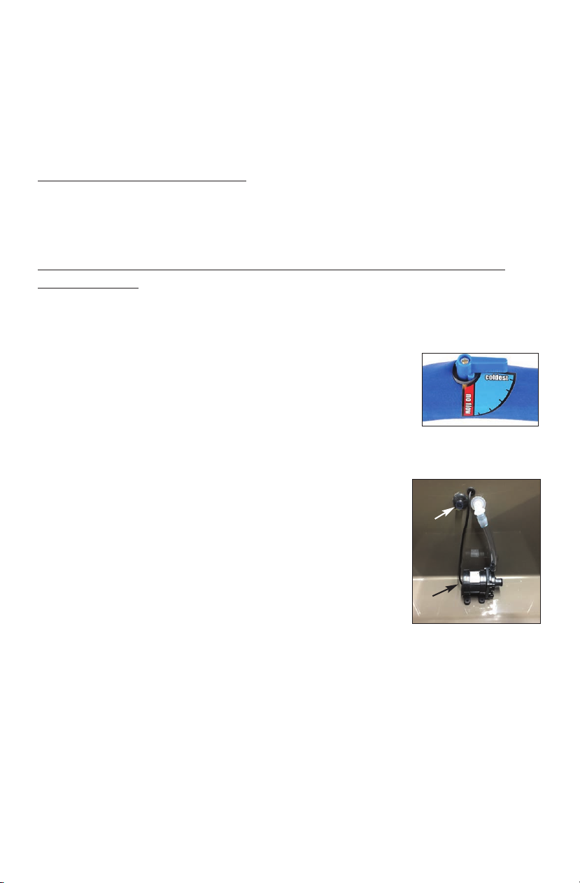
check the pump inlet to ensure it is clear.
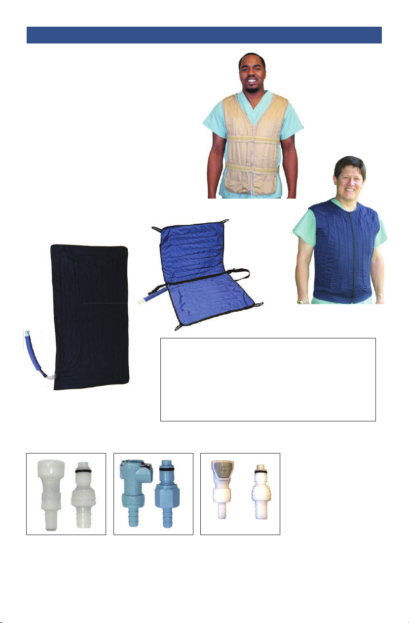
V st, H ad Cap, Wrap, Blank t, S at, or Bladd r
Cleaning: and wash with a mild detergent and air-dry, being careful not to bend the
tubing. The vest, head cap, wrap, blanket, seat, or bladder may also be spot cleaned
with warm soapy water or washed on delicate cycle in a laundry bag. Always air-dry.
Proper handling: The vest, head cap, wrap, blanket, seat, or bladder should never be
roughly handled, bent, folded, crushed or treated harshly. Always hang the vest, head
cap, wrap, blanket, seat, or bladder when not in use!
Proper fit: The vest, head cap, wrap, blanket, seat, or bladder should fit comfortably
on the body and not be over-strained or pulled.
Proper storage: Be sure the vest, head cap, wrap, blanket, seat, or bladder is always
stored in a clean, dry environment with good ventilation.
Care of system: Once every two weeks, and prior to extended storage, pour 16
ounces of Isopropyl Alcohol (rubbing alcohol) in the cooling unit with the ice and
water while the unit is being used. This will keep the system clear of the buildup that
occurs in water-circulation systems.
Ext nd d Storag
Note: It is not possible to remove all of the water from the system and tubing,
therefore before extended storage follow these instructions.
a) When you have finished all of your cooling, prior to extended storage, fill the
reservoir with water to the fill line and add 2 tablespoons of liquid bleach to the
water and mix. This will help keep the system clean.
b) Connect the vest, head cap, wrap, blanket, seat, or bladder to the system and turn
the unit on.
c) Allow the water mixture to circulate for 5 minutes.
d) Turn unit off and unplug the power supply.
e) Carefully drain the water mixture out of the unit and store in a cool dark place
leaving the lid slightly open. (Exposure to sunlight and extreme heat may damage
hoses and unit.)
4
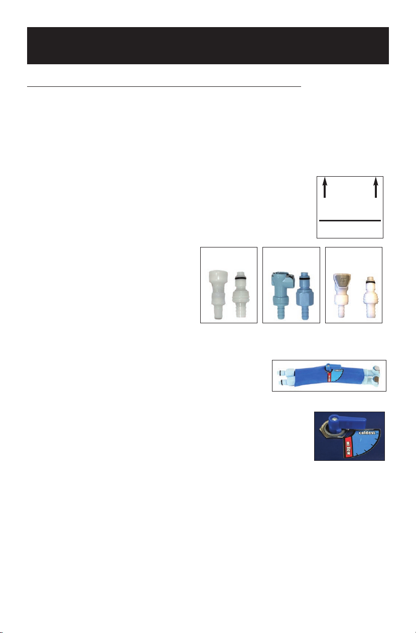
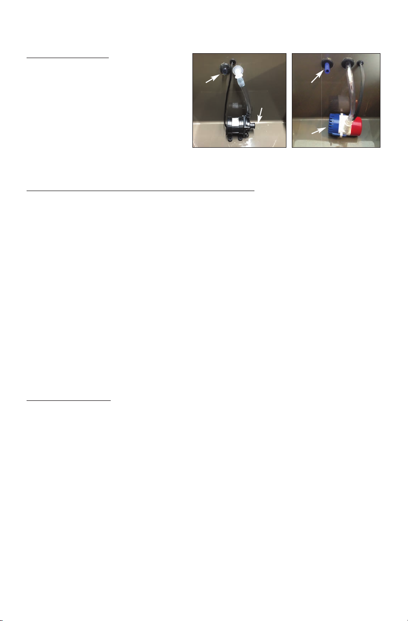
Two styles of pumps may be used depending on your system
R turn
Wat r
Flow
R turn
Wat r
Flow
Pump
Inl t
Pump
Inl t

TROUBLESHOOTING GUIDE
If the possible solutions suggested below do not address your problem, please call
our Customer Service department at 1.800.763.8423 and we will do everything
possible to help.
NOTE: Never run he pump wi hou wa er flowing hrough he lines! This will cause
pump failure.
IF THE PUMP IS NOT RUNNING
Check the wall o tlet to ass re there is power to the nit. Confirm that all power
cords are properly pl gged in and seated. The transformer box has a small light on
it that indicates it is getting power.
IF THE VEST, HEAD CAP, WRAP, BLANKET, SEAT, OR BLADDER IS NOT
GETTING COLD
FIRST: Is water flowing o t of the top water ret rn t be in the cooling reservoir?
If water is NOT flowing o t the top water ret rn t be or it is flowing weakly:
• First: repeat set up steps on pages 1 through 5
• Ensure that the temperature control knob is turned to
maximum cold (“COLDEST”). Always adjust the control knob
to ensure there is a flow of water from the top water return
tube.
• Check the water level in the cooling reservoir. Confirm that
the pump is completely submerged in the water.
• Check for kinks. Ensure there are no kinks in the hoses,
insulated tubing or vest, head cap, wrap, blanket, seat, or
bladder.
• Check for obstructions. Turn the system off. Disconnect
couplings to ensure there is not an obstruction. Remove
anything lodged in the coupling or tubing. Also ensure
there is no obstructions at the bottom pump intake in the
reservoir.
• Check the couplings. Confirm that the vest, head cap,
wrap, blanket, seat, or bladder is properly connected.
(Couplings should “click” when locked) Reseat connectors
between the hose and the vest, head cap, wrap, blanket, seat, or bladder. Turn the
system off, disconnect couplings and reconnect. When connecting the couplings,
be sure the tab on the female coupling is pushed in before trying to connect.
• Check the pump. Occasionally an air bubble can get lodged in the pump intake.
Turn the pump motor vertically to horizontally to dislodge any air bubble.
• Remove the vest, head cap, wrap, blanket, seat, or bladder from the body and run
the system on a flat surface. If there is flow, put on the target body part while
running.
5
Tur k ob to “Coldest”
R turn
Wat r
Flow
Pump

6
Tro bleshooting Tip! A good way to isolate the problem is to remove the
couplings from the insulated tubing attached to the reservoir. To do this simply
turn off the unit, pull off (or cut off) the couplings, place the end of the tubes
over a sink and then turn the system on. If water flows freely, there is an
obstruction in the coupling, vest, head cap, wrap, blanket, seat, or bladder.
Couplings can become blocked with minerals, hair, etc. Use a paper clip to clear
the blockage. A new coupling may be necessary. To reattach the couplings
simply cut the tubing back to unused tubing and push the coupling back into the
tube. See coupling pictures on page 1.
If water IS flowing o t the top water ret rn t be:
• Make sure the reservoir is filled with ice. Note the line inside the cooling reservoir.
• Ensure that the temperature control knob is turned to maximum cold (“COLDEST”)
• If the Chiller System has been purchased, check the chiller for proper operation.
Refer to the chiller manual.
If the nit is leaking at the connections:
If a leak exists, turn off the unit. Disconnect and reconnect the couplings, make
sure both sides are clicked in properly. When connecting tabbed couplings ensure
that the release platform on the female coupling is pressed down prior to insertion.
If the couplings have been replaced be sure the tubing was cut back to unused
tubing before inserting the barbs.
NOTE: Couplings have rubber “O” rings ha can become worn and dysfunc ional.
Replacemen couplings may need o be purchased from Polar Produc s.
Also available from Polar Produc s CoolOR®line:
(Note: vests weigh
3 lbs to 6 lbs
depending on size
and style)
Non-T th r d
Cooling V sts
and Cooling
N ck Wraps

CAUTIONS AND WARNINGS
1) Prior to using this or any body cooling or therapy product for a medical condition
or injury, always consult a licensed healthcare practitioner.
2) Always wear the vest, head cap, wrap, blanket, seat, or bladder over a -shirt or
other clothing; do not wear directly on the skin.
3) Be sure the unit is unplugged prior to filling with water and ice.
4) Refer servicing to qualified personnel at Polar Products Inc.
WARRANTY AND SERVICE
Polar Products, Inc. warrants that the Cool Flow® or CoolO ® System is fit for use
under the normal use for which it is intended and free of any defects in materials
and / or workmanship for 12 months from the date of initial purchase.
Polar's obligation under this warranty is limited to the replacement or repair of any
defective part(s) of this product. If you encounter a problem with your Cool Flow® or
CoolOR® System, please call Polar’s Customer Service Department at 1-800-763-
8423 to obtain a Returned Goods Authorization number (RGA.) To obtain warranty
service on your system, please return the system, dated sales receipt (or packing list,
as proof of purchase) and RGA number to: Polar Products, Inc. 3380 Cavalier rail,
Stow, OH 44224. Please include your phone number, any correspondence, and an
explanation of the problem. Upon receipt, Polar’s Service Department will determine
the cause of failure and, if determined to be an issue covered by the warranty, will
repair (or replace, as necessary) your system and return it to you, postage paid.
Please ote: Coupli gs are a wear item a d may eed to be replaced. They are available
for i dividual purchase.
7
Ou non-tethe ed CoolOR®vests
and neck w aps use Cool58®
Phase Change technology with
cooling packs that will echa ge
in a ef ige ato o even a
coole of ice wate and then
elease thei tempe atu e
at a comfo table 58° F.

8
Four (4) ft. or eight (8) ft. insulated cool water line extensions with couplings
Cooling vest(s) styles:
Adjustable (waist & chest) vest (#CFA)
Heavy Duty Adjustable vest (#CFA- D)
eavier water lines and higher flow rate.
Fitted (#CFF)
Fitted vest
Embroider your name on any of our
vests! Call Polar for details.
Cooling reservoir size and number of systems:
13-quart one (1) or two (2) person system
15-quart one (1) or two (2) person system
19-quart one (1) through four (4) person system
30-quart one (1) through six (6) person system
Breakaway
Coupli gs
Tabbed
Coupli gs
Tabbed Euro
Coupli gs
Adjustable vest
Cooling
Seats
Cooling Blankets
Options Availabl for Your Cool Flow®or CoolOR®Syst m

9
#XT4 & #XT8 4 ft. and 8 ft. long hose assemblies with couplings
#CM-Tabbed Dry, quick-disconnect male coupling (used with the
CF-Tabbed coupling)
#CF-Tabbed Dry, quick-disconnect female coupling with metal tab
#CBF-Breakaway Dry, high-flow, breakaway quick disconnect female coupling
#CBM-Breakaway Dry, high-flow, breakaway quick disconnect male coupling
#TG 12 Volt Grounded Transformer
#CM-E Euro Dry, quick disconnect male coupling (used with the
CF-E Euro coupling)
#CF-E Euro Dry, quick disconnect female coupling with plastic tab.
See coupling pictures on page 8 for reference.
Available accessories and replacement parts:
Pumps, tube insulation and all other components are available for purchase. Call
Polar for information and pricing.
Polar will manufacture custom designs for unique cooling applications (we have
eve ma ufactured special cooli g u its for u ma ed avy vessels a d special HD
3D cameras used by Hollywood.)
Easy to use Lithium-Ion
Battery Pack (#BPL)
eliminates cords and
connected adapters. Will
cool for up to 6+ hours on
a single charge!
Options Availabl for Your Cool Flow®or CoolOR®Syst m
Cooling Head and
Head & Neck Caps

800-763-8423 polarproducts.com
POLAR PRODUCTS
3380 Cavalier Trail • Stow, O 44224
Other manuals for Cool Flow
1
This manual suits for next models
1
Table of contents
Other Polar Electro Medical Equipment manuals