Medical Solutions 6000 Series User manual

5640.A
TEMP 2
FLUID WARMER
OPERATORS MANUAL
6000 Series
Medical Solutions, Inc
3901 Centerview Drive, Suite L
Chantilly, VA 20151
800-435-7600
703-834-0039 (Fax)

5640.A
2
TEMP 2Fluid Warmer
Read and understand the Operators Manual before using the TEMP 2FLUID WARMER.
Intended Use
The TEMP 2Fluid Warmer is designed to store, warm and maintain the temperature of
I.V. and irrigation fluid bags or bottles prior to their use.
It is suggested that each facility should contact the fluid manufacturer to obtain the
manufacturer’s specifications for time and temperature for the fluids being
warmed.
Unit Description
The TEMP 2Fluid Warmer is a mobile unit consisting of one cabinet with two internal
shelves. A central temperature controller is used to control the independent heating of
each shelf. The controller will display two temperatures in its display. The top display
number (in red) will indicate the temperature of the top shelf heater plate. The bottom
display number (in green) will indicate the temperature of the bottom shelf heater plate.
During the time that the controller is directing the unit to warm, a light will illuminate in
the upper left corner of the display.
The Documentoris designed to assist in the compliance with JCAHOstandard MM
2.20 and the fluid manufacturer’s specifications for time and temperature.
JCAHO is a registered trademark of the Joint Commission on Accreditation of Healthcare Organizations
Important Labels or Directions
Model/Serial Number label
Caution: Replace fuses as marked.
Caution: Electric shock hazard, do not remove protective panel. Refer servicing to Qualified
Personnel.
Caution: Verify temperature of warmed items before use.
Danger: Risk of explosion if used in the presence of flammable anesthetics.
Warning: Unit not intended for blood or blood products.
Caution: Unit may tip when exposed to a 10-degree angle

5640.A
3
Specifications
Classification Class 1
Dimensions 14” (wide) x 19” (deep) x 33 ¾” (tall)
Capacity Each Shelf
12 – One Liter Bags, or
6 - Three Liter Bags, or
2 - Five Liter Bags
Design Floor model with 2 locking casters
2 non-locking casters
Construction Electro Galvanneal Steel
Temperature Control Specifications
Temperature Setting Range Ambient to 120F
Factory Preset Temperature 104°F
Ambient Operating Conditions
Storage Temperature -40º to +80º C (-40º to +176º F)
Humidity Conditions 0 to 90% up to 40º C non-condensing
Ambient Operating Temperature -10º to +55º C (+14 to 131º F)
Atmospheric Pressure During Minimum of 16.288 in. Hg
Transporting
Electrical Requirements
Power Requirements 110 / 120 VAC, 60 HZ
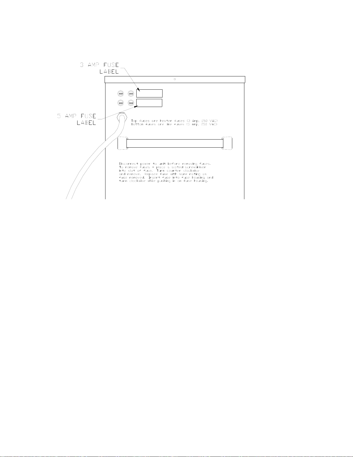
Fusing 2 each 5 Amps Mains
2 each 3 Amps Heaters
2 each 0.5 Amps Documentor Outlet
Amperage Consumed 4 Amps
Heater Wattage 2 each 250 watt heaters
Thermal Cutout Temperature 140º F Manual Reset (plate temperature)
The TEMP 2System has not been evaluated for compliance for Electro-magnetic compatibility
(EMC).
5640.A
4
Set-up Instructions
1. Remove the TEMP 2from the shipping box; check before operating to ensure that all of the
packaging material and manuals are removed from the cabinet.
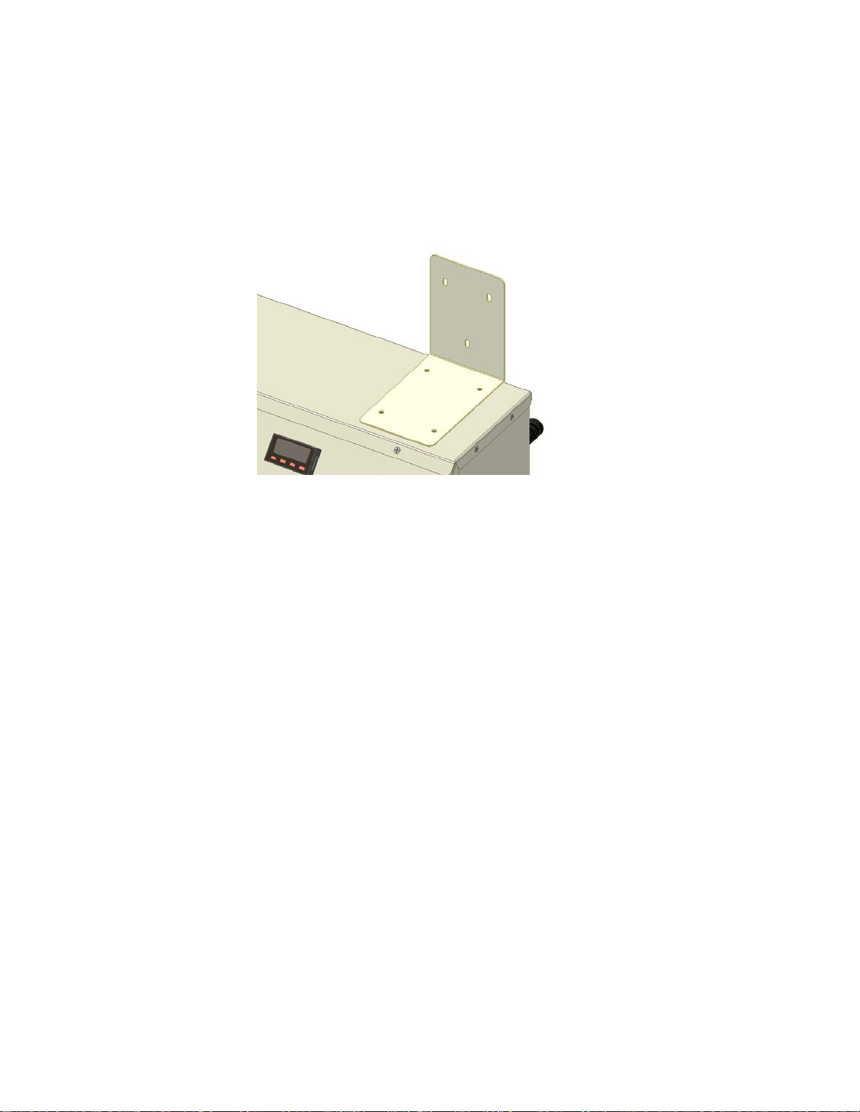
2. Locate The Documentorand remove it from the shipping box. Attach The Documentorto
the TEMP 2following the instructions below.
3. Remove the 4 screws in the top of the TEMP 2. Align the four holes in the TEMP 2
Time/Clock Mounting Bracket and secure using these 4 screws.
4. Remove the 3 screws in the back of The Documentor. Attach The Documentorto the
mounting bracket using these 3 screws.
5. Plug the Documentorinto the Hospital Grade Receptacle located on the back of the TEMP
2.
6. Move the TEMP 2to the desired location, check that power switch is off and plug the
power cord into an approved outlet.
DocumentorInstructions
1) Prior to loading the cabinet with bags, use the Documentorto label the bags with a future
date that follows the manufacturer’s recommendation for the length of time a bag is to be
warmed.
“Future Date Label”
To create a future date label: (See the DocumentorResetting Instructions for adjusting the
clock date)
i) Hold the Label sheet face up.
ii) Line up the arrow on the Documentorunder the words “Remove Fluid By:” on the
label
iii) Push the label sheet towards the arrow until the Documentoris activated.
iv) Place a label on each IV bag for documentation and compliance purposes.
2) Load the labeled bags of solution into the TEMP 2®through the door.

5640.A
5
Operating Instructions
1. Turn the unit on by pressing the power switch. The switch will illuminate when energized.
The controller will perform a self-test then will display the current temperature of the shelf
heater plates. The factory temperature setting is 104 degrees F. To change the temperature
setting, follow the instructions below.
2. The controller will display 2 temperatures in its display. The top display number (in red) will
indicate the temperature of the top shelf heater plate. The bottom display number (in green)
will indicate the temperature of the bottom shelf heater plate. During the time that the
controller is directing the unit to warm a light will illuminate in the upper left corner of the
display.
3. To change the temperature setting, follow the instructions below.
TO CHANGE THE SET POINT
PRESS THE INDEX KEY (LEFT MOST KEY) TO VIEW SET POINT ONE (SP1).
TOP SHELF.
PRESS THE INDEX KEY TWICE (LEFT MOST KEY) TO VIEW SET POINT TWO
(SP2). BOTTOM SHELF.
PRESS THE UP OR DOWN ARROW KEYS TO CHANGE THE SET POINT.
PRESS THE ENTER KEY (RIGHT MOST KEY) TO ACCEPT NEW SET POINT.
PRESS THE INDEX KEY.
3) The shelves will operate independently from each other. When one shelf is not in use
decrease the set point for that shelf (below ambient temperature) to reduce operating cost.
4) Reload the TEMP 2after removing the bag.
NOTES:
The TEMP 2may be left on continually without harm to the unit. It is suggested that each
facility should contact the fluid manufacturer to obtain the manufacturer’s specifications
for time and temperature for the fluids being warmed.
The TEMP 2is not intended for Blood or Blood Products.
In the event that fluid should spill inside the cabinet – unplug the unit to prevent an
electrical shock hazard and refer to step #4 of the Cleaning instructions.

5640.A
6
Documentor™Resetting Instructions
TO CHANGE THE DATE:
1. Plug Documentor™ into an electrical outlet.
2. Press and hold blue RESET button located on the bottom of the Documentor™.
3. While holding down the RESET button, press and hold the • right button on the front
panel.
4. While holding the • right button, release the RESET button.
5. When Prog appears in the display, release the • right button, Prog finishes.
6. Tap the • right button again. The display will show 0000 and the 1st digit will flash.
7. Tap the left button until the number 8 appears then Tap the • right button twice so the
third 0 is flashing.
8. Tap the left button until the number 8 appears in the third position then Tap the
• Right button.
9. Tap the left button until the number 8 appears in the fourth position. The display
should read 8088 then Tap the • right button.
10. When the display flashes all four digits, Tap the • right button
11. The display flashes P1(date).
12. Tap the • right button, the small digits on the left, representing the year, will flash.
13. Tap the left button until the desired number appears then Tap the • right button. The
digits representing the month should flash.
14. Tap the left button until the desired number appears then Tap the • right button. The
digits representing the day should flash.
15. Tap the left button until the desired number appears then Tap the • right button.
16. When the desired date is set Tap the • right button until the display flashes P1 (date).
17. Tap the blue RESET to return to the standard display.
TO CHANGE THE TIME:
18. Follow steps 1-11.
19. Tap the left button, when the display flashes P2 cloc, Tap the • right button.
20. The hour format will flash (12 or 24). If necessary, tap the left button until 24 flashes.
Tap the • right button
21. The hour digits will flash; Tap the left button until the desired setting is achieved. (the
hour must be set in military time 3:05 pm = 15:05) Tap the • right button
22. The minutes digits will flash; Tap the left button until the desired setting is achieved.
Tap the • right button twice.
23. The display will flash P2 Cloc, Press and release the blue RESET button.
5640.A
7
Cleaning Instructions
1. Turn the TEMP 2off and disconnect it from the power source.
2. Wipe down the cabinet with a damp cloth using a general hospital cleaner (i.e. Isopropyl
Alcohol) as needed, following the manufacturers instructions for the cleaner.
3. Avoid contact with the electrical connections and the electrical components.
4. In the event that excessive fluids enter the cabinet, disconnect power to the unit and refer to
qualified service personnel. Remove the service panel (qualified person) and remove any
liquid and/or dry components. Perform any necessary hospital electrical safety checks before
returning the TEMP 2to service.
Trouble Shooting
1. If the unit fails to warm, check the following:
a. Check to see that the TEMP 2is plugged in and the power switch is on.
b. Check the set point setting so that the controller is calling for the unit to operate.
2. If the unit overheats, call Medical Solutions, Inc.
3. Contact Medical Solutions, Inc. for technical assistance at 800-435-7600.
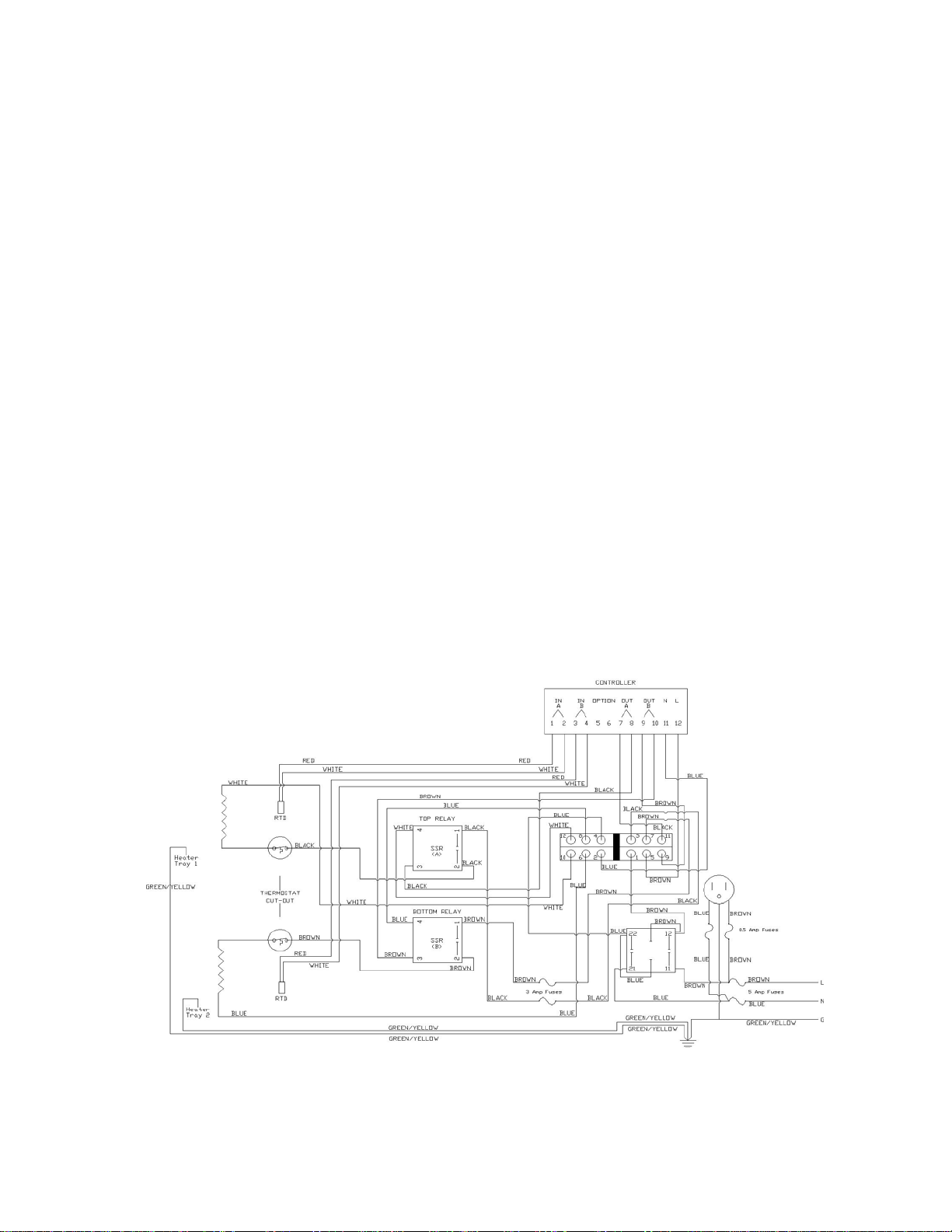
Electrical Schematic

5640.A
8
Service Panel Location and Removal
Remove the top plate to access the electrical compartment.
5640.A
9
Fuse removal instructions

5640.A
10
Preventive Maintenance Plan
The TEMP 2temperature controller should be verified every five (5) years. Medical Solutions,
Inc. requires the use of the following items to accurately measure the bag temperature for
verification.
Fluke 51II Digital Thermometer
6” Long .093” Diameter Type T Needle Thermocouple
(with the Thermocouple calibrated to the Thermometer)
With the outer wrap still on a three liter IV fluid bag, pierce the bag through the needle injection
port on the bag with an 18ga needle to make it easier to insert the Thermocouple. Insert the
Thermocouple through the pierced needle injection port. Place the fluid bag onto the center of
the bottom shelf. Load the top shelf with an additional three liter IV fluid bag. Feed the
Thermocouple wire attached to the Fluke Thermometer out of the cabinet positioning the probe
in the center of the bag. Close the door.
Turn the power on to the TEMP 2. Adjust the temperature controller set point temperature to
104F for both shelves. Allow the unit to operate for a minimum of 6 hours before verifying the
temperatures. After the allotted time, compare the temperature reading on the controller to the
temperature reading on the Fluke Thermometer, the two temperatures should be within two
degrees Fahrenheit of each other. If the two temperature readings are within two degrees
Fahrenheit of each other, the temperature controller has been verified. If they are not, please
contact Medical Solutions, Inc. at 800-435-7600.
Repeat the calibration process for the top shelf of the TEMP 2.
If a Fluke Digital Thermometer is not available an alternative method to verify the controller is
to use a glass laboratory thermometer. Place 1 three liter IV bag onto the center of each of the
shelves. Turn the power on and adjust the temperature controller set point temperature to 104F
for both shelves. Allow the unit to operate for a minimum of 6 hours before verifying the
temperatures. Remove the bag and place the end of the glass thermometer on the top and in the
middle of the bag. Fold the bag over the thermometer and hold for approximately two minutes
or until the mercury stops moving. If the reading on the thermometer is between 100.4F and
105.8F the temperature controller has been verified. If they are not, please contact Medical
Solutions, Inc. at 800-435-7600.
Repeat the calibration process for the other shelf of the TEMP 2.

5640.A
11
LIMITED WARRANTY
For one year from the date of shipment to the Buyer (the “Warranty Period”), MSI warrants that the Equipment
provided to the Buyer shall be free from defects in workmanship and material. In the event of a breach of this
warranty during the Warranty Period, MSI shall, at its option, repair or replace the Equipment, and Buyer’s remedies
are limited to such repair or replacement. MSI DISCLAIMS ALL OTHER WARRANTIES, EXPRESSED OR
IMPLIED, INCLUDING THE WARRANTIES OF MERCHANTABILITY OR FITNESS FOR A PARTICULAR
PURPOSE. IN NO EVENT SHALL MSI BE LIABLE FOR DIRECT, INDIRECT, PUNITIVE, ECONOMIC,
CONSEQUENTIAL OR OTHER DAMAGES, INCLUDING BUT NOT LIMITED TO LOST PROFITS.
To enable MSI to administer the Warranty properly, Buyer shall (1) register the Warranty using the form provided
below, and (2) promptly notify MSI of any claim hereunder. As a condition to the Warranty, Buyer shall use and
maintain the Equipment according to the provisions of the Operator’s service manual.
IMPORTANT: THIS IS YOUR TEMP 2®WARRANTY REGISTRATION
Please register your warranty by filling out this page and send it to Medical
Solutions, Inc. within 30 days of purchase.
A. Hospital Name:
B. Mailing Address:
C. City: State: Zip Code:
D. Contact Name:
E. Date Purchased:
F. Serial Number:
G. Department Purchased For:
COPY THIS PAGE AND MAIL TO:
Medical Solutions, Inc.
3901 Centerview Drive, Suite L
Chantilly, Virginia 20151
Fax number 703-834-0039
This manual suits for next models
1
Table of contents
Other Medical Solutions Medical Equipment manuals


Popular Medical Equipment manuals by other brands


InTouch Health
InTouch Health InTouch Lite 4 Quick reference guide

burmeier
burmeier ARMINIA II instruction manual

Optopol
Optopol REVO nx user manual

ResMed
ResMed Ultra Mirage Clinicians Guide

Olympus
Olympus BX3-SSU instructions

Graham Field
Graham Field LUMEX TENDERCLOUD AQTC8035 Installation & operation instructions

Promeba
Promeba PB-410 Series user guide

Otto Bock
Otto Bock AxonArm Ergo 12K501 Instructions for use

Gentherm
Gentherm Electri-Cool II Operation and technical manual

Mirion Technologies
Mirion Technologies BIODEX ECONO 058-726 Operation manual

NanoVibronix
NanoVibronix PAINSHIELD MD user manual

Aspira
Aspira P1211EM Instructions for use