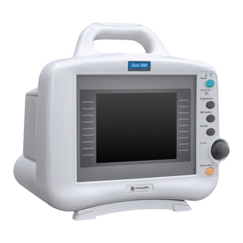
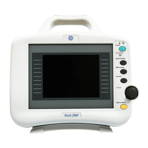
GE Medical Systems Dash 3000 User manual

GE Medical Systems
Information Technologies
g
gemedicalsystem.com
Dash3000/4000
Patient Monitor
Service Manual
2000966-105 Revision B

T-2 Dash 3000/4000 Patient Monitor Revision B
2000966-105 28 February 2002
NOTE: Due to continuing product innovation, specifications in this
manual are subject to change without notice.
Listed below are GE Medical Systems Information Technologies’ trademarks. All other trademarks contained
herein are the property of their respective owners.
900 SC, ACCUSKETCH, AccuVision, APEX, AQUA-KNOT, ARCHIVIST, Autoseq, BABY MAC, C Qwik
Connect, CardioServ, CardioSmart, CardioSys, CardioWindow, CASE, CD TELEMETRY, CENTRA, CHART
GUARD, CINE 35, CORO, COROLAN, COROMETRICS, Corometrics Sensor Tip, CRG PLUS, DASH,
Digistore, Digital DATAQ, E for M, EAGLE, Event-Link, FMS 101B, FMS 111, HELLIGE, IMAGE STORE,
INTELLIMOTION, IQA, LASER SXP, MAC, MAC-LAB, MACTRODE, MANAGED USE, MARQUETTE,
MARQUETTE MAC, MARQUETTE MEDICAL SYSTEMS, MARQUETTE UNITY NETWORK, MARS,
MAX, MEDITEL, MEI, MEI in the circle logo, MEMOPORT, MEMOPORT C, MINISTORE, MINNOWS,
Monarch 8000, MULTI-LINK, MULTISCRIPTOR, MUSE, MUSE CV, Neo-Trak, NEUROSCRIPT,
OnlineABG, OXYMONITOR, Pres-R-Cuff, PRESSURE-SCRIBE, QMI, QS, Quantitative Medicine,
Quantitative Sentinel, RAC RAMS, RSVP, SAM, SEER, SILVERTRACE, SOLAR, SOLARVIEW, Spectra
400, Spectra-Overview, Spectra-Tel, ST GUARD, TRAM, TRAM-NET, TRAM-RAC, TRAMSCOPE, TRIM
KNOB, Trimline, UNION STATION, UNITY logo, UNITY NETWORK, Vari-X, Vari-X Cardiomatic,
VariCath, VARIDEX, VAS, and Vision Care Filter are trademarks of GE Medical Systems Information
Technologies registered in the United States Patent and Trademark Office.
12SL, 15SL, Access, AccuSpeak, ADVANTAGE, BAM, BODYTRODE, Cardiomatic, CardioSpeak, CD
TELEMETRY®-LAN, CENTRALSCOPE, Corolation, EDIC, EK-Pro, Event-Link Cirrus, Event-Link
Cumulus, Event-Link Nimbus, HI-RES, ICMMS, IMAGE VAULT, IMPACT.wf, INTER-LEAD, IQA,
LIFEWATCH, Managed Use, MARQUETTE PRISM, MARQUETTE®RESPONDER, MENTOR, MicroSmart,
MMS, MRT, MUSE CardioWindow, NST PRO, NAUTILUS, O2SENSOR, Octanet, OMRS, PHi-Res,
Premium, Prism, QUIK CONNECT V, QUICK CONNECT, QT Guard, SMART-PAC, SMARTLOOK, Spiral
Lok, Sweetheart, UNITY, Universal, Waterfall, and Walkmom are trademarks of GE Medical Systems
Information Technologies.
© GE Medical Systems Information Technologies, 2002. All rights reserved.
Revision B Dash 3000/4000 Patient Monitor i
2000966-105
CONTENTS
1INTRODUCTION . . . . . . . . . . . . . . . . . . . . . . . . . . . . . . . . . . . . . . . . . . . .1-1
Manual Information . . . . . . . . . . . . . . . . . . . . . . . . . . . . . . . . . . . . . . . . . .1-3
Revision History . . . . . . . . . . . . . . . . . . . . . . . . . . . . . . . . . . . . . . . . .1-3
Manual Purpose . . . . . . . . . . . . . . . . . . . . . . . . . . . . . . . . . . . . . . . . .1-3
Intended Audience . . . . . . . . . . . . . . . . . . . . . . . . . . . . . . . . . . . . . . .1-3
Safety Information . . . . . . . . . . . . . . . . . . . . . . . . . . . . . . . . . . . . . . . . . . .1-4
Responsibility of the Manufacturer . . . . . . . . . . . . . . . . . . . . . . . . . . .1-4
General . . . . . . . . . . . . . . . . . . . . . . . . . . . . . . . . . . . . . . . . . . . . . . . .1-4
Warnings, Cautions, and Notes . . . . . . . . . . . . . . . . . . . . . . . . . . . . .1-5
Equipment Symbols . . . . . . . . . . . . . . . . . . . . . . . . . . . . . . . . . . . . . .1-6
Service Information . . . . . . . . . . . . . . . . . . . . . . . . . . . . . . . . . . . . . . . . . .1-8
Service Requirements . . . . . . . . . . . . . . . . . . . . . . . . . . . . . . . . . . . .1-8
Equipment Identification . . . . . . . . . . . . . . . . . . . . . . . . . . . . . . . . . . .1-8
2EQUIPMENT OVERVIEW . . . . . . . . . . . . . . . . . . . . . . . . . . . . . . . . . . . . .2-1
Components . . . . . . . . . . . . . . . . . . . . . . . . . . . . . . . . . . . . . . . . . . . . . . .2-3
The Monitoring System . . . . . . . . . . . . . . . . . . . . . . . . . . . . . . . . . . .2-3
The Patient Monitor . . . . . . . . . . . . . . . . . . . . . . . . . . . . . . . . . . . . . .2-3
Right Side View . . . . . . . . . . . . . . . . . . . . . . . . . . . . . . . . . . . . . .2-4
Left Side View . . . . . . . . . . . . . . . . . . . . . . . . . . . . . . . . . . . . . . .2-4
Back View . . . . . . . . . . . . . . . . . . . . . . . . . . . . . . . . . . . . . . . . . .2-5
Optional Alarm Light Indicator . . . . . . . . . . . . . . . . . . . . . . . . . . .2-5
User Interface . . . . . . . . . . . . . . . . . . . . . . . . . . . . . . . . . . . . . . . . . . .2-6
Flat Panel Display . . . . . . . . . . . . . . . . . . . . . . . . . . . . . . . . . . . .2-6
Trim Knob Control . . . . . . . . . . . . . . . . . . . . . . . . . . . . . . . . . . . .2-6
Power Key . . . . . . . . . . . . . . . . . . . . . . . . . . . . . . . . . . . . . . . . . .2-6
Function Keys . . . . . . . . . . . . . . . . . . . . . . . . . . . . . . . . . . . . . . .2-6
Optional RAC 2A Module Housing . . . . . . . . . . . . . . . . . . . . . . . . . . .2-8
Optional Dash Port Docking Station . . . . . . . . . . . . . . . . . . . . . . . . . .2-8
Optional ICG Module . . . . . . . . . . . . . . . . . . . . . . . . . . . . . . . . . . . . .2-8
Optional Wireless LAN System . . . . . . . . . . . . . . . . . . . . . . . . . . . . .2-9
Access Points . . . . . . . . . . . . . . . . . . . . . . . . . . . . . . . . . . . . . . .2-9
Optional Remote Control . . . . . . . . . . . . . . . . . . . . . . . . . . . . . . . . . .2-9
Software Packages and Software Options . . . . . . . . . . . . . . . . . . . . . . .2-10
Technical Specifications . . . . . . . . . . . . . . . . . . . . . . . . . . . . . . . . . . . . .2-11
Performance Specifications . . . . . . . . . . . . . . . . . . . . . . . . . . . . . . .2-11
Display . . . . . . . . . . . . . . . . . . . . . . . . . . . . . . . . . . . . . . . . . . . .2-11
Controls . . . . . . . . . . . . . . . . . . . . . . . . . . . . . . . . . . . . . . . . . . .2-11
Alarms . . . . . . . . . . . . . . . . . . . . . . . . . . . . . . . . . . . . . . . . . . . .2-12
ECG . . . . . . . . . . . . . . . . . . . . . . . . . . . . . . . . . . . . . . . . . . . . . . . . .2-12
Invasive Blood Pressure (BP) . . . . . . . . . . . . . . . . . . . . . . . . . . . . .2-13
Noninvasive Blood Pressure (NBP) . . . . . . . . . . . . . . . . . . . . . . . . .2-14
GE Pulse Oximetry (SPO2) . . . . . . . . . . . . . . . . . . . . . . . . . . . . . . .2-15
Masimo SET SPO2 Module . . . . . . . . . . . . . . . . . . . . . . . . . . . . . . .2-15
Cardiac Output (CO) . . . . . . . . . . . . . . . . . . . . . . . . . . . . . . . . . . . .2-16
Respiration . . . . . . . . . . . . . . . . . . . . . . . . . . . . . . . . . . . . . . . . . . . .2-16

CONTENTS:
ii Dash 3000/4000 Patient Monitor Revision B
2000966-105
Temperature (TEMP) . . . . . . . . . . . . . . . . . . . . . . . . . . . . . . . . . . . .2-17
Carbon Dioxide (CO2) . . . . . . . . . . . . . . . . . . . . . . . . . . . . . . . . . . .2-17
Analog Output . . . . . . . . . . . . . . . . . . . . . . . . . . . . . . . . . . . . . . . . .2-19
Defibrillator Synchronization Pulse . . . . . . . . . . . . . . . . . . . . . . . . . .2-19
Battery . . . . . . . . . . . . . . . . . . . . . . . . . . . . . . . . . . . . . . . . . . . . . . .2-20
Paper Recorder . . . . . . . . . . . . . . . . . . . . . . . . . . . . . . . . . . . . . . . .2-20
RF Wireless LAN . . . . . . . . . . . . . . . . . . . . . . . . . . . . . . . . . . . . . . .2-20
Environmental Specifications . . . . . . . . . . . . . . . . . . . . . . . . . . . . . .2-21
Physical Specifications . . . . . . . . . . . . . . . . . . . . . . . . . . . . . . . . . . .2-21
Certification . . . . . . . . . . . . . . . . . . . . . . . . . . . . . . . . . . . . . . . . . . .2-22
Safety . . . . . . . . . . . . . . . . . . . . . . . . . . . . . . . . . . . . . . . . . . . . .2-22
Electromagnetic Compatibility Compliance (EMC) . . . . . . . . . .2-22
FCC Compliance Information Statement . . . . . . . . . . . . . . . . . .2-23
3INSTALLATION . . . . . . . . . . . . . . . . . . . . . . . . . . . . . . . . . . . . . . . . . . . . . 3-1
Connections . . . . . . . . . . . . . . . . . . . . . . . . . . . . . . . . . . . . . . . . . . . . . . .3-3
Back Panel Connections . . . . . . . . . . . . . . . . . . . . . . . . . . . . . . . . . .3-3
ETHERNET . . . . . . . . . . . . . . . . . . . . . . . . . . . . . . . . . . . . . . . . .3-3
RAC 2A Housing Connectors . . . . . . . . . . . . . . . . . . . . . . . . . . .3-3
Remote Control . . . . . . . . . . . . . . . . . . . . . . . . . . . . . . . . . . . . . .3-4
Defib Sync . . . . . . . . . . . . . . . . . . . . . . . . . . . . . . . . . . . . . . . . . .3-4
AC Power . . . . . . . . . . . . . . . . . . . . . . . . . . . . . . . . . . . . . . . . . . .3-4
Front Panel Indicators . . . . . . . . . . . . . . . . . . . . . . . . . . . . . . . . . . . .3-5
AC Power Indicator . . . . . . . . . . . . . . . . . . . . . . . . . . . . . . . . . . .3-5
Battery Power Indicator . . . . . . . . . . . . . . . . . . . . . . . . . . . . . . . .3-5
Battery Charging/Ready Indicators . . . . . . . . . . . . . . . . . . . . . . .3-5
Power Up . . . . . . . . . . . . . . . . . . . . . . . . . . . . . . . . . . . . . . . . . . . . . .3-5
Optional Ethernet Communication . . . . . . . . . . . . . . . . . . . . . . . . . . . . . .3-6
Overview . . . . . . . . . . . . . . . . . . . . . . . . . . . . . . . . . . . . . . . . . . . . . .3-6
Twisted Pair . . . . . . . . . . . . . . . . . . . . . . . . . . . . . . . . . . . . . . . . . . . .3-6
Concentrator . . . . . . . . . . . . . . . . . . . . . . . . . . . . . . . . . . . . . . . . . . . .3-6
Node . . . . . . . . . . . . . . . . . . . . . . . . . . . . . . . . . . . . . . . . . . . . . . . . . .3-7
Segment and Branch . . . . . . . . . . . . . . . . . . . . . . . . . . . . . . . . . . . . .3-7
Repeater . . . . . . . . . . . . . . . . . . . . . . . . . . . . . . . . . . . . . . . . . . . . . . .3-7
Bridge . . . . . . . . . . . . . . . . . . . . . . . . . . . . . . . . . . . . . . . . . . . . . . . . .3-8
Twisted Pair Cabling (10BaseT) . . . . . . . . . . . . . . . . . . . . . . . . . . . . .3-8
Symbol PC Card (Wireless LAN) . . . . . . . . . . . . . . . . . . . . . . . . . . . .3-8
4MAINTENANCE . . . . . . . . . . . . . . . . . . . . . . . . . . . . . . . . . . . . . . . . . . . . .4-1
Maintenance Schedule . . . . . . . . . . . . . . . . . . . . . . . . . . . . . . . . . . . . . . .4-3
Manufacturer Recommendations . . . . . . . . . . . . . . . . . . . . . . . . . . . .4-3
Visual Inspection . . . . . . . . . . . . . . . . . . . . . . . . . . . . . . . . . . . . . . . . . . . .4-4
Cleaning . . . . . . . . . . . . . . . . . . . . . . . . . . . . . . . . . . . . . . . . . . . . . . . . . .4-5
Cleaning Precautions . . . . . . . . . . . . . . . . . . . . . . . . . . . . . . . . . . . . .4-5
Cleaning the Display . . . . . . . . . . . . . . . . . . . . . . . . . . . . . . . . . . . . .4-5
Exterior Cleaning . . . . . . . . . . . . . . . . . . . . . . . . . . . . . . . . . . . . . . . .4-5
Cleaning the Print Head . . . . . . . . . . . . . . . . . . . . . . . . . . . . . . . . . . .4-6
Materials Required . . . . . . . . . . . . . . . . . . . . . . . . . . . . . . . . . . . .4-6
Procedure . . . . . . . . . . . . . . . . . . . . . . . . . . . . . . . . . . . . . . . . . .4-6

CONTENTS:
Revision B Dash 3000/4000 Patient Monitor iii
2000966-105
Battery Maintenance . . . . . . . . . . . . . . . . . . . . . . . . . . . . . . . . . . . . . . . . .4-7
Charging . . . . . . . . . . . . . . . . . . . . . . . . . . . . . . . . . . . . . . . . . . . . . . .4-7
Conditioning the Batteries . . . . . . . . . . . . . . . . . . . . . . . . . . . . . . . . .4-7
Frequency Guidelines . . . . . . . . . . . . . . . . . . . . . . . . . . . . . . . . .4-7
Recommendations . . . . . . . . . . . . . . . . . . . . . . . . . . . . . . . . . . . .4-7
Procedure . . . . . . . . . . . . . . . . . . . . . . . . . . . . . . . . . . . . . . . . . .4-7
Replacing the Batteries . . . . . . . . . . . . . . . . . . . . . . . . . . . . . . . . . . .4-8
Recycling the Batteries . . . . . . . . . . . . . . . . . . . . . . . . . . . . . . . . . . . .4-8
Electrical Safety Tests . . . . . . . . . . . . . . . . . . . . . . . . . . . . . . . . . . . . . . .4-9
General . . . . . . . . . . . . . . . . . . . . . . . . . . . . . . . . . . . . . . . . . . . . . . . .4-9
Recommendations . . . . . . . . . . . . . . . . . . . . . . . . . . . . . . . . . . . . . . .4-9
Test Conditions . . . . . . . . . . . . . . . . . . . . . . . . . . . . . . . . . . . . . .4-9
Test Equipment . . . . . . . . . . . . . . . . . . . . . . . . . . . . . . . . . . . . . .4-9
Power Outlet Test . . . . . . . . . . . . . . . . . . . . . . . . . . . . . . . . . . . . . . .4-11
Ground (Earth) Integrity . . . . . . . . . . . . . . . . . . . . . . . . . . . . . . . . . .4-11
Ground Continuity Test . . . . . . . . . . . . . . . . . . . . . . . . . . . . . . .4-11
Impedance of Protective Earth Connection . . . . . . . . . . . . . . . .4-12
Ground (Earth) Wire Leakage Current Tests . . . . . . . . . . . . . . . . . .4-13
Enclosure Leakage Current Test . . . . . . . . . . . . . . . . . . . . . . . . . . .4-14
Patient (Source) Leakage Current Test . . . . . . . . . . . . . . . . . . . . . .4-15
Patient (Sink) Leakage Current Test
(Mains Voltage on the Applied Part) . . . . . . . . . . . . . . . . . . . . . . .4-16
Test Completion . . . . . . . . . . . . . . . . . . . . . . . . . . . . . . . . . . . . . . . .4-17
Checkout Procedures . . . . . . . . . . . . . . . . . . . . . . . . . . . . . . . . . . . . . . .4-18
Manufacturer Recommended Test Equipment . . . . . . . . . . . . . . . . .4-18
Monitor Power-up Tests . . . . . . . . . . . . . . . . . . . . . . . . . . . . . . . . . .4-20
ECG Tests . . . . . . . . . . . . . . . . . . . . . . . . . . . . . . . . . . . . . . . . . . . .4-21
5 Lead ECG Test . . . . . . . . . . . . . . . . . . . . . . . . . . . . . . . . . . . .4-21
12SL and ACI-TIPI ECG Test . . . . . . . . . . . . . . . . . . . . . . . . . .4-22
Respiration Tests . . . . . . . . . . . . . . . . . . . . . . . . . . . . . . . . . . . . . . .4-24
Temperature Tests . . . . . . . . . . . . . . . . . . . . . . . . . . . . . . . . . . . . . .4-25
Cardiac Output Tests . . . . . . . . . . . . . . . . . . . . . . . . . . . . . . . . . . . .4-26
Test with Cardiac Output Simulator II . . . . . . . . . . . . . . . . . . . .4-26
Test with Marq II Simulator . . . . . . . . . . . . . . . . . . . . . . . . . . . .4-27
Invasive Blood Pressure Tests . . . . . . . . . . . . . . . . . . . . . . . . . . . . .4-28
BP1 Connector (AR1) Tests . . . . . . . . . . . . . . . . . . . . . . . . . . .4-28
BP2 Connector (PA2) Tests . . . . . . . . . . . . . . . . . . . . . . . . . . .4-29
Pulse Oximetry Tests for GE SPO2 Oximeter . . . . . . . . . . . . . . . . .4-30
Pulse Oximetry Tests for Masimo SET SPO2 . . . . . . . . . . . . . . . . .4-32
Noninvasive Blood Pressure Tests . . . . . . . . . . . . . . . . . . . . . . . . .4-34
Analog Output and Defibrillator Synchronization Tests . . . . . . . . . .4-36
DEFIB Sync Connector: ECG . . . . . . . . . . . . . . . . . . . . . . . . . .4-36
DEFIB Sync Connector: Arterial BP . . . . . . . . . . . . . . . . . . . . .4-36
DEFIB Sync Connector: Marker Out (Frequency) . . . . . . . . . . .4-37
DEFIB Sync Connector: Marker Out (Pulse Width) . . . . . . . . . .4-37
Battery Tests . . . . . . . . . . . . . . . . . . . . . . . . . . . . . . . . . . . . . . . . . .4-39
Graph Test . . . . . . . . . . . . . . . . . . . . . . . . . . . . . . . . . . . . . . . . . . . .4-39
Graph Speed Test . . . . . . . . . . . . . . . . . . . . . . . . . . . . . . . . . . . . . .4-39
Display Test . . . . . . . . . . . . . . . . . . . . . . . . . . . . . . . . . . . . . . . . . . .4-40
Speaker Test . . . . . . . . . . . . . . . . . . . . . . . . . . . . . . . . . . . . . . . . . .4-40
Network Test . . . . . . . . . . . . . . . . . . . . . . . . . . . . . . . . . . . . . . . . . .4-40
Remote Control Test . . . . . . . . . . . . . . . . . . . . . . . . . . . . . . . . . . . .4-40
RF LAN Test (option) . . . . . . . . . . . . . . . . . . . . . . . . . . . . . . . . . . . .4-40
Dash Port Docking Station Test . . . . . . . . . . . . . . . . . . . . . . . . . . . .4-41

CONTENTS:
iv Dash 3000/4000 Patient Monitor Revision B
2000966-105
Electrical Safety Tests . . . . . . . . . . . . . . . . . . . . . . . . . . . . . . . .4-41
Operation . . . . . . . . . . . . . . . . . . . . . . . . . . . . . . . . . . . . . . . . . .4-41
RAC 2A Module Housing Test . . . . . . . . . . . . . . . . . . . . . . . . . . . . .4-41
Electrical Safety . . . . . . . . . . . . . . . . . . . . . . . . . . . . . . . . . . . . .4-41
Operation . . . . . . . . . . . . . . . . . . . . . . . . . . . . . . . . . . . . . . . . . .4-41
Checkout Procedures Completion . . . . . . . . . . . . . . . . . . . . . . . . . .4-41
PM Form . . . . . . . . . . . . . . . . . . . . . . . . . . . . . . . . . . . . . . . . . . . . . .4-41
Repair Log . . . . . . . . . . . . . . . . . . . . . . . . . . . . . . . . . . . . . . . . . . . .4-42
5TROUBLESHOOTING . . . . . . . . . . . . . . . . . . . . . . . . . . . . . . . . . . . . . . . . 5-1
Service Menus . . . . . . . . . . . . . . . . . . . . . . . . . . . . . . . . . . . . . . . . . . . . .5-3
Boot Loader Service Menu . . . . . . . . . . . . . . . . . . . . . . . . . . . . . . . . .5-3
Main Menu Service Mode Menu . . . . . . . . . . . . . . . . . . . . . . . . . . . . .5-4
About Service Mode Menu Option Items . . . . . . . . . . . . . . . . . . .5-5
Service Mode Menu Option Items . . . . . . . . . . . . . . . . . . . . . . . .5-5
Review Errors . . . . . . . . . . . . . . . . . . . . . . . . . . . . . . . . . . . . . . . . . . .5-8
About the Monitor Error Log . . . . . . . . . . . . . . . . . . . . . . . . . . . .5-8
Downloading the Error Log . . . . . . . . . . . . . . . . . . . . . . . . . . . . .5-8
Accessing the Review Errors Menu Option Item . . . . . . . . . . . . .5-8
Error Log Information . . . . . . . . . . . . . . . . . . . . . . . . . . . . . . . . . . . . .5-9
Error Logs . . . . . . . . . . . . . . . . . . . . . . . . . . . . . . . . . . . . . . . . . . . . . .5-9
Severity of the Error . . . . . . . . . . . . . . . . . . . . . . . . . . . . . . . . . . .5-9
Battery Alarms and Messages . . . . . . . . . . . . . . . . . . . . . . . . . . . . . . . .5-10
Alarm Conditions . . . . . . . . . . . . . . . . . . . . . . . . . . . . . . . . . . . . . . .5-10
Error Message . . . . . . . . . . . . . . . . . . . . . . . . . . . . . . . . . . . . . . . . .5-11
Power Source Tests . . . . . . . . . . . . . . . . . . . . . . . . . . . . . . . . . . . . . . . .5-12
Wall Receptacle . . . . . . . . . . . . . . . . . . . . . . . . . . . . . . . . . . . . . . . .5-12
Power Cord and Plug . . . . . . . . . . . . . . . . . . . . . . . . . . . . . . . . . . . .5-13
Data Acquisition Tests . . . . . . . . . . . . . . . . . . . . . . . . . . . . . . . . . . . . . .5-14
ECG Functions . . . . . . . . . . . . . . . . . . . . . . . . . . . . . . . . . . . . . . . . .5-14
ECG Waveforms Display Incorrectly . . . . . . . . . . . . . . . . . . . . .5-15
ECG Waveforms Do Not Display At All . . . . . . . . . . . . . . . . . . .5-15
Lead Fail Functions . . . . . . . . . . . . . . . . . . . . . . . . . . . . . . . . . . . . .5-15
Pace Detect Functions . . . . . . . . . . . . . . . . . . . . . . . . . . . . . . . . . . .5-16
Pace Detect Functions Do Not Work Properly . . . . . . . . . . . . . .5-16
Invasive Blood Pressure Functions . . . . . . . . . . . . . . . . . . . . . . . . .5-17
Setup BP1 . . . . . . . . . . . . . . . . . . . . . . . . . . . . . . . . . . . . . . . . .5-17
Setup BP2 . . . . . . . . . . . . . . . . . . . . . . . . . . . . . . . . . . . . . . . . .5-17
Zero-Reference Both BP’s . . . . . . . . . . . . . . . . . . . . . . . . . . . . .5-17
Generate Dynamic BP Waveforms . . . . . . . . . . . . . . . . . . . . . .5-17
Verify Dynamic BP Results . . . . . . . . . . . . . . . . . . . . . . . . . . . .5-17
Generate Static BP Waveforms . . . . . . . . . . . . . . . . . . . . . . . . .5-18
BP Waveforms Do Not Appear Correctly On The Display . . . . .5-18
BP Waveforms Do Not Appear On The Display At All . . . . . . . .5-18
Respiration Functions . . . . . . . . . . . . . . . . . . . . . . . . . . . . . . . . . . . .5-19
No Respiration Waveform or Rate Appear on the Display . . . .5-19
Respiration Functions Work Properly on Patient Simulator but not on
Actual Patient . . . . . . . . . . . . . . . . . . . . . . . . . . . . . . . . . . . . .5-20
Noninvasive Blood Pressure Functions . . . . . . . . . . . . . . . . . . . . . .5-21
NBP Alarms Occur Continuously . . . . . . . . . . . . . . . . . . . . . . . .5-21
Wireless LAN Troubleshooting . . . . . . . . . . . . . . . . . . . . . . . . . . . . . . . .5-22

CONTENTS:
Revision B Dash 3000/4000 Patient Monitor v
2000966-105
Service Tips . . . . . . . . . . . . . . . . . . . . . . . . . . . . . . . . . . . . . . . . . . . . . .5-24
Fault/Symptom Analysis . . . . . . . . . . . . . . . . . . . . . . . . . . . . . . . . . .5-24
Acquisition PCB Symptoms . . . . . . . . . . . . . . . . . . . . . . . . . . . . . . .5-26
Processor PCB Symptoms . . . . . . . . . . . . . . . . . . . . . . . . . . . . . . . .5-26
Error Messages . . . . . . . . . . . . . . . . . . . . . . . . . . . . . . . . . . . . . . . . . . .5-27
Language-Specific Information . . . . . . . . . . . . . . . . . . . . . . . . . . . . . . . .5-29
French Language Information . . . . . . . . . . . . . . . . . . . . . . . . . . . . .5-29
Hungarian, Polish, and Russian, Language Information . . . . . . . . .5-29
Chinese and Japanese Language Information . . . . . . . . . . . . . . . . .5-29
6CONFIGURATION . . . . . . . . . . . . . . . . . . . . . . . . . . . . . . . . . . . . . . . . . . . 6-1
Configuring a Monitor . . . . . . . . . . . . . . . . . . . . . . . . . . . . . . . . . . . . .6-3
General . . . . . . . . . . . . . . . . . . . . . . . . . . . . . . . . . . . . . . . . . . . .6-3
Main Menu Selections . . . . . . . . . . . . . . . . . . . . . . . . . . . . . . . . . . . .6-5
Set Unit Name . . . . . . . . . . . . . . . . . . . . . . . . . . . . . . . . . . . . . . .6-5
Set Bed Number . . . . . . . . . . . . . . . . . . . . . . . . . . . . . . . . . . . . .6-5
Patient-Monitor Type . . . . . . . . . . . . . . . . . . . . . . . . . . . . . . . . . .6-6
Set Graph Locations . . . . . . . . . . . . . . . . . . . . . . . . . . . . . . . . . .6-6
Communication Confirmation . . . . . . . . . . . . . . . . . . . . . . . . . . .6-7
Problems? . . . . . . . . . . . . . . . . . . . . . . . . . . . . . . . . . . . . . . . . . .6-7
Admit Menu . . . . . . . . . . . . . . . . . . . . . . . . . . . . . . . . . . . . . . . . .6-8
Boot Code Selections . . . . . . . . . . . . . . . . . . . . . . . . . . . . . . . . . . . . .6-9
Set Defib Sync Voltage and Pulse Width . . . . . . . . . . . . . . . . . . .6-9
Set Line Frequency . . . . . . . . . . . . . . . . . . . . . . . . . . . . . . . . . . .6-9
Set CIC and QS Protocol . . . . . . . . . . . . . . . . . . . . . . . . . . . . . . .6-9
Set MUSE Protocol . . . . . . . . . . . . . . . . . . . . . . . . . . . . . . . . . . .6-9
Transcutaneous Pace Blank Length . . . . . . . . . . . . . . . . . . . . .6-10
Set Country Selection . . . . . . . . . . . . . . . . . . . . . . . . . . . . . . . .6-10
Wireless LAN . . . . . . . . . . . . . . . . . . . . . . . . . . . . . . . . . . . . . . .6-10
Set Language . . . . . . . . . . . . . . . . . . . . . . . . . . . . . . . . . . . . . .6-11
Completion . . . . . . . . . . . . . . . . . . . . . . . . . . . . . . . . . . . . . . . . .6-11
Advanced User Procedures . . . . . . . . . . . . . . . . . . . . . . . . . . . . . . .6-12
Procedures . . . . . . . . . . . . . . . . . . . . . . . . . . . . . . . . . . . . . . . .6-12
Set Time and Date . . . . . . . . . . . . . . . . . . . . . . . . . . . . . . . . . . .6-12
Transfer Monitor Defaults . . . . . . . . . . . . . . . . . . . . . . . . . . . . .6-13
Change Ethernet Address . . . . . . . . . . . . . . . . . . . . . . . . . . . . .6-16
Review Errors . . . . . . . . . . . . . . . . . . . . . . . . . . . . . . . . . . . . . .6-16
Transferring Error Logs . . . . . . . . . . . . . . . . . . . . . . . . . . . . . . .6-19
General . . . . . . . . . . . . . . . . . . . . . . . . . . . . . . . . . . . . . . . . . . .6-19
Access the COPY LOGS Menu . . . . . . . . . . . . . . . . . . . . . . . . .6-20
Select the Monitoring Device . . . . . . . . . . . . . . . . . . . . . . . . . . .6-20
Select the Error Log Date . . . . . . . . . . . . . . . . . . . . . . . . . . . . .6-20
Copy Error Logs . . . . . . . . . . . . . . . . . . . . . . . . . . . . . . . . . . . . .6-21
Eject Floppy . . . . . . . . . . . . . . . . . . . . . . . . . . . . . . . . . . . . . . . 6-21

CONTENTS:
vi Dash 3000/4000 Patient Monitor Revision B
2000966-105
7CALIBRATION . . . . . . . . . . . . . . . . . . . . . . . . . . . . . . . . . . . . . . . . . . . . .7-1
Hardware Calibration . . . . . . . . . . . . . . . . . . . . . . . . . . . . . . . . . . . . . . . .7-3
NBP, Analog Output ECG, Analog Output BP, and End-tidal CO2
Software Calibration . . . . . . . . . . . . . . . . . . . . . . . . . . . . . . . . . . . . . . . . .7-4
NBP Calibration . . . . . . . . . . . . . . . . . . . . . . . . . . . . . . . . . . . . . . . . .7-4
In General . . . . . . . . . . . . . . . . . . . . . . . . . . . . . . . . . . . . . . . . . .7-4
Required Test Equipment . . . . . . . . . . . . . . . . . . . . . . . . . . . . . .7-4
Calibration Procedure . . . . . . . . . . . . . . . . . . . . . . . . . . . . . . . . .7-5
ECG or BP Calibration . . . . . . . . . . . . . . . . . . . . . . . . . . . . . . . . . . . .7-7
Before you Begin . . . . . . . . . . . . . . . . . . . . . . . . . . . . . . . . . . . . .7-7
ECG Calibration . . . . . . . . . . . . . . . . . . . . . . . . . . . . . . . . . . . . . .7-7
BP Calibration . . . . . . . . . . . . . . . . . . . . . . . . . . . . . . . . . . . . . . .7-8
End-tidal CO2 Calibration . . . . . . . . . . . . . . . . . . . . . . . . . . . . . . . . . .7-8
8FIELD REPLACEABLE UNITS AND UPGRADES . . . . . . . . . . . . . . . . . .8-1
Disassembly Guidelines . . . . . . . . . . . . . . . . . . . . . . . . . . . . . . . . . . . . . .8-3
Tools Required . . . . . . . . . . . . . . . . . . . . . . . . . . . . . . . . . . . . . . . . . .8-3
Before Disassembly . . . . . . . . . . . . . . . . . . . . . . . . . . . . . . . . . . . . . .8-3
Hardware Assemblies . . . . . . . . . . . . . . . . . . . . . . . . . . . . . . . . . . . .8-3
PCB Assemblies . . . . . . . . . . . . . . . . . . . . . . . . . . . . . . . . . . . . . . . . .8-4
Electrostatic Discharge (ESD) Precautions . . . . . . . . . . . . . . . . .8-4
After Reassembly . . . . . . . . . . . . . . . . . . . . . . . . . . . . . . . . . . . . . . . .8-5
Handle Assembly . . . . . . . . . . . . . . . . . . . . . . . . . . . . . . . . . . . . . . . . . . .8-7
Removing the Handle Assembly . . . . . . . . . . . . . . . . . . . . . . . . . . . .8-7
Replacing or Upgrading the Dash 3000 Alarm Light Option . . . . . . .8-8
Display Assembly Components . . . . . . . . . . . . . . . . . . . . . . . . . . . . . . . .8-9
Removing the Display Assembly from the Main Unit . . . . . . . . . . . . .8-9
Replacing the Backlight Inverter PCB . . . . . . . . . . . . . . . . . . . . . . .8-13
Replacing the Key Pad Assembly . . . . . . . . . . . . . . . . . . . . . . . . . .8-14
Replacing the LCD Color Display . . . . . . . . . . . . . . . . . . . . . . . . . . .8-15
Replacing or Upgrading the Dash 4000 Alarm Light Option . . . . . .8-16
Replacing the Dash 4000 Front Panel PCB . . . . . . . . . . . . . . . . . . .8-17
. . . . . . . . . . . . . . . . . . . . . . . . . . . . . . . . . . . . . . . . . . . . . . . . . . . . .8-17
Main Unit Components . . . . . . . . . . . . . . . . . . . . . . . . . . . . . . . . . . . . . .8-18
DAS and NBP Assemblies . . . . . . . . . . . . . . . . . . . . . . . . . . . . . . . .8-18
Main and/or Power Supply Assemblies, Speaker or RF LAN
Upgrade . . . . . . . . . . . . . . . . . . . . . . . . . . . . . . . . . . . . . . . . . . . . .8-21
Processor/Power Management PCB and Battery Assembly . . . . . .8-22
Power Supply Assembly . . . . . . . . . . . . . . . . . . . . . . . . . . . . . . . . . .8-24
Speaker . . . . . . . . . . . . . . . . . . . . . . . . . . . . . . . . . . . . . . . . . . . . . .8-25
RF LAN Upgrade Instructions . . . . . . . . . . . . . . . . . . . . . . . . . . . . .8-26
Verify the Wireless LAN ID Number . . . . . . . . . . . . . . . . . . . . .8-35
Verify Wireless LAN Communications . . . . . . . . . . . . . . . . . . . .8-35
Optional DDW Writer Replacement/Upgrade . . . . . . . . . . . . . . . . . . . . .8-36
Replacement . . . . . . . . . . . . . . . . . . . . . . . . . . . . . . . . . . . . . . . . . .8-36
Upgrade . . . . . . . . . . . . . . . . . . . . . . . . . . . . . . . . . . . . . . . . . . . . . .8-36

CONTENTS:
Revision B Dash 3000/4000 Patient Monitor vii
2000966-105
9ASSEMBLY DRAWINGS . . . . . . . . . . . . . . . . . . . . . . . . . . . . . . . . . . . . .9-1
Introduction . . . . . . . . . . . . . . . . . . . . . . . . . . . . . . . . . . . . . . . . . . . . . . . .9-3
Theory Of Operation . . . . . . . . . . . . . . . . . . . . . . . . . . . . . . . . . . . . . . . . .9-4
Components . . . . . . . . . . . . . . . . . . . . . . . . . . . . . . . . . . . . . . . . . . . .9-4
Overall Monitor Block Diagram . . . . . . . . . . . . . . . . . . . . . . . . . . . . . .9-4
Power Supply . . . . . . . . . . . . . . . . . . . . . . . . . . . . . . . . . . . . . . . . . . .9-5
Data Acquisition System (DAS) . . . . . . . . . . . . . . . . . . . . . . . . . . . . .9-5
DAS Block Diagram with GE SPO2 . . . . . . . . . . . . . . . . . . . . . .9-6
Processor/Power Management Subsystem . . . . . . . . . . . . . . . . . . .9-12
Overview . . . . . . . . . . . . . . . . . . . . . . . . . . . . . . . . . . . . . . . . . .9-12
Block Diagram . . . . . . . . . . . . . . . . . . . . . . . . . . . . . . . . . . . . . .9-13
Main Microcontroller . . . . . . . . . . . . . . . . . . . . . . . . . . . . . . . . .9-14
System Control Logic . . . . . . . . . . . . . . . . . . . . . . . . . . . . . . . . .9-15
Memory . . . . . . . . . . . . . . . . . . . . . . . . . . . . . . . . . . . . . . . . . . .9-15
Real-Time Clock . . . . . . . . . . . . . . . . . . . . . . . . . . . . . . . . . . . .9-15
Audio Subsystem . . . . . . . . . . . . . . . . . . . . . . . . . . . . . . . . . . . .9-15
Video Subsystem . . . . . . . . . . . . . . . . . . . . . . . . . . . . . . . . . . . .9-15
Defib Sync . . . . . . . . . . . . . . . . . . . . . . . . . . . . . . . . . . . . . . . . .9-16
Optional Thermal Printer . . . . . . . . . . . . . . . . . . . . . . . . . . . . . .9-16
Optional Alarm Light Indicator . . . . . . . . . . . . . . . . . . . . . . . . . .9-16
PC Card . . . . . . . . . . . . . . . . . . . . . . . . . . . . . . . . . . . . . . . . . . .9-16
Peripheral Expansion Interface . . . . . . . . . . . . . . . . . . . . . . . . .9-16
Optional Unity Network Communication . . . . . . . . . . . . . . . . . .9-17
Ethernet Priority . . . . . . . . . . . . . . . . . . . . . . . . . . . . . . . . . . . . .9-17
Async Communication . . . . . . . . . . . . . . . . . . . . . . . . . . . . . . . .9-17
Debug Monitor and Diagnostic LEDs . . . . . . . . . . . . . . . . . . . . .9-17
Battery Subsystem . . . . . . . . . . . . . . . . . . . . . . . . . . . . . . . . . . .9-18
Optional Thermal Printer . . . . . . . . . . . . . . . . . . . . . . . . . . . . . . . . .9-18
Speaker . . . . . . . . . . . . . . . . . . . . . . . . . . . . . . . . . . . . . . . . . . . . . .9-18
Handle Subassembly . . . . . . . . . . . . . . . . . . . . . . . . . . . . . . . . . . . .9-18
Interfaces . . . . . . . . . . . . . . . . . . . . . . . . . . . . . . . . . . . . . . . . . . . . .9-19
Ethernet . . . . . . . . . . . . . . . . . . . . . . . . . . . . . . . . . . . . . . . . . . .9-19
AUX . . . . . . . . . . . . . . . . . . . . . . . . . . . . . . . . . . . . . . . . . . . . . .9-19
Defib Sync . . . . . . . . . . . . . . . . . . . . . . . . . . . . . . . . . . . . . . . . .9-19
Peripheral Expansion . . . . . . . . . . . . . . . . . . . . . . . . . . . . . . . . .9-19
Setup and Configuration . . . . . . . . . . . . . . . . . . . . . . . . . . . . . . . . . .9-19
Program Code Storage . . . . . . . . . . . . . . . . . . . . . . . . . . . . . . .9-19
Monitor Settings . . . . . . . . . . . . . . . . . . . . . . . . . . . . . . . . . . . . .9-19
Patient Data Storage . . . . . . . . . . . . . . . . . . . . . . . . . . . . . . . . .9-19
Time and Date . . . . . . . . . . . . . . . . . . . . . . . . . . . . . . . . . . . . . .9-19
Error Log . . . . . . . . . . . . . . . . . . . . . . . . . . . . . . . . . . . . . . . . . .9-20
Electrical Diagram, PN 2004323, Revision D . . . . . . . . . . . . . . . . . . . . .9-21
Dash 3000/4000 Assembly, PN 2004323, Revision D . . . . . . . . . . . . . .9-22
Part List, PN 419031-003, Rev. C . . . . . . . . . . . . . . . . . . . . . . . . . . . . .9-27
Dash 4000 Display Assembly, PN 2004272-001, Rev. C . . . . . . . . . . . .9-28
Parts List, PN 2004272-001, Rev. C . . . . . . . . . . . . . . . . . . . . . . . . . . . .9-29
Dash 3000/4000 Back, PN 2001875, Revision D . . . . . . . . . . . . . . . . . .9-30
Parts List , PN 2001875, Rev. D . . . . . . . . . . . . . . . . . . . . . . . . . . . . . . .9-31
Field Replaceable Units (FRU’s) . . . . . . . . . . . . . . . . . . . . . . . . . . . . . .9-32
Dash 3000 FRUs . . . . . . . . . . . . . . . . . . . . . . . . . . . . . . . . . . . . . . .9-32

CONTENTS:
viii Dash 3000/4000 Patient Monitor Revision B
2000966-105
Dash 4000 FRUs . . . . . . . . . . . . . . . . . . . . . . . . . . . . . . . . . . . . . . .9-32
Port Connections . . . . . . . . . . . . . . . . . . . . . . . . . . . . . . . . . . . . . . . . . .9-34
Invasive Blood Pressure Cable Connector . . . . . . . . . . . . . . . . . . . .9-34
GE Pulse Oximetry (SpO2) Cable Connector . . . . . . . . . . . . . . . . .9-35
Masimo SET Pulse Oximetry (SpO2) Cable Connector . . . . . . . . . .9-36
Temperature/CO Cable Connector . . . . . . . . . . . . . . . . . . . . . . . . .9-36
Capnostat III (CO2) Cable Connector . . . . . . . . . . . . . . . . . . . . . . .9-37
NBP Connector . . . . . . . . . . . . . . . . . . . . . . . . . . . . . . . . . . . . . . . .9-38
ECG Cable Connector . . . . . . . . . . . . . . . . . . . . . . . . . . . . . . . . . . .9-38
Power Entry Connector . . . . . . . . . . . . . . . . . . . . . . . . . . . . . . . . . .9-39
Network Interface Connector . . . . . . . . . . . . . . . . . . . . . . . . . . . . . .9-39
Auxiliary Communication Connector . . . . . . . . . . . . . . . . . . . . . . . .9-40
Defib Sync Connector . . . . . . . . . . . . . . . . . . . . . . . . . . . . . . . . . . .9-40
Peripheral Expansion Interface Connector . . . . . . . . . . . . . . . . . . . .9-41

Revision B Dash 3000/4000 Patient Monitor 1-1
2000966-105
1INTRODUCTION

INTRODUCTION:
1-2 Dash 3000/4000 Patient Monitor Revision B
2000966-105
For your notes

INTRODUCTION: Manual Information
Revision B Dash 3000/4000 Patient Monitor 1-3
2000966-105
Manual Information
Revision History Each page of this manual has the document part number and revision
letter at the bottom of the page. The revision letter identifies the
document’s update level. The revision history of this document is
summarized below.
Manual Purpose This manual supplies technical information for service representatives
and technical personnel so they can maintain the equipment to the
assembly level. Use it as a guide for maintenance and electrical repairs
considered field repairable. Where necessary the manual identifies
additional sources of relevant information and technical assistance.
See the operator’s manual for the instructions necessary to operate the
equipment safely in accordance with its function and intended use.
Intended Audience This manual is intended for service representatives and technical
personnel who maintain, troubleshoot, or repair this equipment.
Revision History
Revision Date Comment
A 19 December 2002 Initial release of this manual.
B 28 February 2002 Corrections were made.

INTRODUCTION: Safety Information
1-4 Dash 3000/4000 Patient Monitor Revision B
2000966-105
Safety Information
Responsibility of the
Manufacturer GE Medical Systems Information Technologies is responsible for the
effects of safety, reliability, and performance only if:
• Assembly operations, extensions, readjustments, modifications, or
repairs are carried out by persons authorized by GE.
• The electrical installation of the relevant room complies with the
requirements of the appropriate regulations.
• The equipment is used in accordance with the instructions for use.
General This device is intended for use under the direct supervision of a licensed
health care practitioner.
This device is not intended for home use.
Federal law restricts this device to be sold by or on the order of a
physician.
Contact GE for information before connecting any devices to the
equipment that are not recommended in this manual.
Parts and accessories used must meet the requirements of the applicable
IEC 601 series safety standards, and/or the system configuration must
meet the requirements of the IEC 60601-1-1 medical electrical systems
standard.
Periodically, and whenever the integrity of the device is in doubt, test all
functions.
The use of ACCESSORY equipment not complying with the equivalent
safety requirements of this equipment may lead to a reduced level of
safety of the resulting system. Consideration relating to the choice shall
include:
• use of the accessory in the PATIENT VICINITY; and
• evidence that the safety certification of the ACCESSORY has been
performed in accordance to the appropriate IEC 60601-1 and/or IEC
60601-1-1 harmonized national standard.
If the installation of the equipment, in the USA, will use 240V rather
than 120V, the source must be a center-tapped, 240V, single-phase
circuit.

INTRODUCTION: Safety Information
Revision B Dash 3000/4000 Patient Monitor 1-5
2000966-105
Warnings, Cautions,
and Notes The terms danger, warning, and caution are used throughout this
manual to point out hazards and to designate a degree or level or
seriousness. Familiarize yourself with their definitions and significance.
Hazard is defined as a source of potential injury to a person.
DANGER indicates an imminent hazard which, if not avoided, will
result in death or serious injury.
WARNING indicates a potential hazard or unsafe practice which, if not
avoided, could result in death or serious injury.
CAUTION indicates a potential hazard or unsafe practice which, if not
avoided, could result in minor personal injury or product/property
damage.
NOTE provides application tips or other useful information to assure
that you get the most from your equipment.

INTRODUCTION: Safety Information
1-6 Dash 3000/4000 Patient Monitor Revision B
2000966-105
Equipment Symbols Some of the following symbols appear on the equipment.
ATTENTION: Consult accompanying documents before using the
equipment.
In Europe, this symbol means dangerous or high voltage. In the United
States, this symbol represents the caution notice below:
To reduce the risk of electric shock, do NOT remove cover (or back).
Refer servicing to qualified personnel.
Defibrillator-proof type CF equipment; type CF equipment is
specifically designed for applications where a conductive connection
directly to the heart is established. The paddles indicate the equipment
is defibrillator proof.
Defibrillator-proof type BF equipment; type BF equipment is suitable
for intentional external and internal application to the patient,
excluding direct cardiac application. Type BF equipment is type B
equipment with an F-type isolated (floating) part. The paddles indicate
the equipment is defibrillator proof.
Type B equipment; type B equipment is suitable for intentional
external and internal application to the patient, excluding direct
cardiac application.
Equipotentiality
Alternating current (AC)
Power; I= ON; O= OFF
Fuse
Battery
Indicates the Ethernet connection for the monitor.

INTRODUCTION: Safety Information
Revision B Dash 3000/4000 Patient Monitor 1-7
2000966-105
Press to open.
POWER
GRAPH GO/STOP
NBP GO/STOP
ZERO ALL
SILENCE ALARM/ADMIT
Medical Equipment
With respect to electric shock, fire and mechanical hazards only in
accordance with UL 2601-1, and CAN/CSA C22.2 NO. 601.1.
PRESS
814A
815A
816A
817A
818A
4P41

INTRODUCTION: Service Information
1-8 Dash 3000/4000 Patient Monitor Revision B
2000966-105
Service Information
Service
Requirements Follow the service requirements listed below.
• Refer equipment servicing to GE authorized service personnel only.
• Any unauthorized attempt to repair equipment under warranty voids
that warranty.
• It is the user’s responsibility to report the need for service to GE or to
one of their authorized agents.
• Failure on the part of the responsible individual, hospital, or
institution using this equipment to implement a satisfactory
maintenance schedule may cause undue equipment failure and
possible health hazards.
• Regular maintenance, irrespective of usage, is essential to ensure
that the equipment will always be functional when required.
Equipment
Identification Every GE device has a unique serial number for identification. A sample
of the information found on a serial number label is shown below.
D 0 XX 0005 G XX
Month
Manufactured
A = January
B = February
C = March
D = April
E = May
F = June
G = July
H = August
J = September
K = October
L = November
M = December
Year
Manufactured
0 = 2000
1 = 2001
2 = 2002
(and so on)
Product Code
Two-character
product
descriptor
Product
Sequence
Number
Manufacturing
number (of total
units
manufactured)
Device Characteristics
One or two letters that
further describe the unit,
for example:
P = prototype not
conforming to marketing
specification
R = refurbished equipment
S = special product
documented under Specials
part numbers
U = upgraded unit
Division
F = Cardiology
G = Monitoring

Revision B Dash 3000/4000 Patient Monitor 2-1
2000966-105
2EQUIPMENT OVERVIEW

EQUIPMENT OVERVIEW:
2-2 Dash 3000/4000 Patient Monitor Revision B
2000966-105
For your notes
This manual suits for next models
1
Table of contents
Other GE Medical Systems Medical Equipment manuals

GE Medical Systems
GE Medical Systems marquette Dash 2000 User manual

GE Medical Systems
GE Medical Systems MAC 1200 User manual

GE Medical Systems
GE Medical Systems PRN 50 User manual

GE Medical Systems
GE Medical Systems LOGIQ 7 User manual

GE Medical Systems
GE Medical Systems LOGIQ 7 User manual

GE Medical Systems
GE Medical Systems LOGIQ 500 User manual

GE Medical Systems
GE Medical Systems LOGIQ 7 User manual

GE Medical Systems
GE Medical Systems LOGIQ 400 User manual

GE Medical Systems
GE Medical Systems LOGIQ ?200 User manual

GE Medical Systems
GE Medical Systems 500 User manual