Introduction
© 2010 Baker Hughes, a GE company – All rights reserved. 8000/8100/8200 Series Instruction Manual-English | 1
1. Installation
1.1 Introduction
The 8XXX Series uses TERPS (trench etched resonant sensor) technology. The RPS 8XXX
produces a frequency and diode voltage output. The DPS 8XXX includes a microprocessor to
produce a serial digital output.
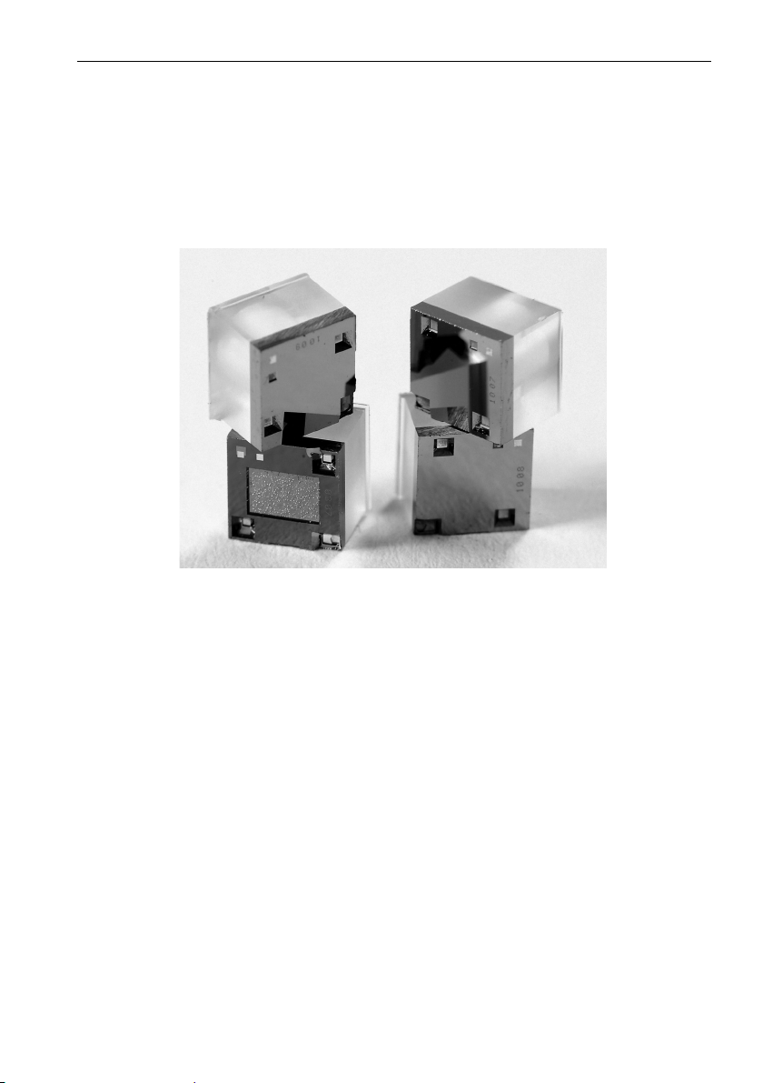
Figure 1-1: TERPS Sensor Chip
The 80XX, 82XX and 83XX are harsh media isolated product. Isolation is achieved by
hermetically sealing the sensor chip in an oil filled chamber. The weight of this oil gives a
g-sensitivity as a pressure offset error.
The 81XX is not a harsh media isolated product. The pressure media comes directly into
contact with the sensor chip. Care must be taken to ensure the pressure media does not
damage the sensor chip. There is negligible change in offset due to mounting position and
vibration.
To calibrate the 8XXX Series, the unit is mounted vertically with the pressure port at the
lowest point. Orientation other than this produces a pressure offset error as specified in the
data sheet. The error is most noticeable at lower pressure ranges.
Note: The g-sensitivity will also create an error in a high vibration environment and the
unit should be mounted accordingly.
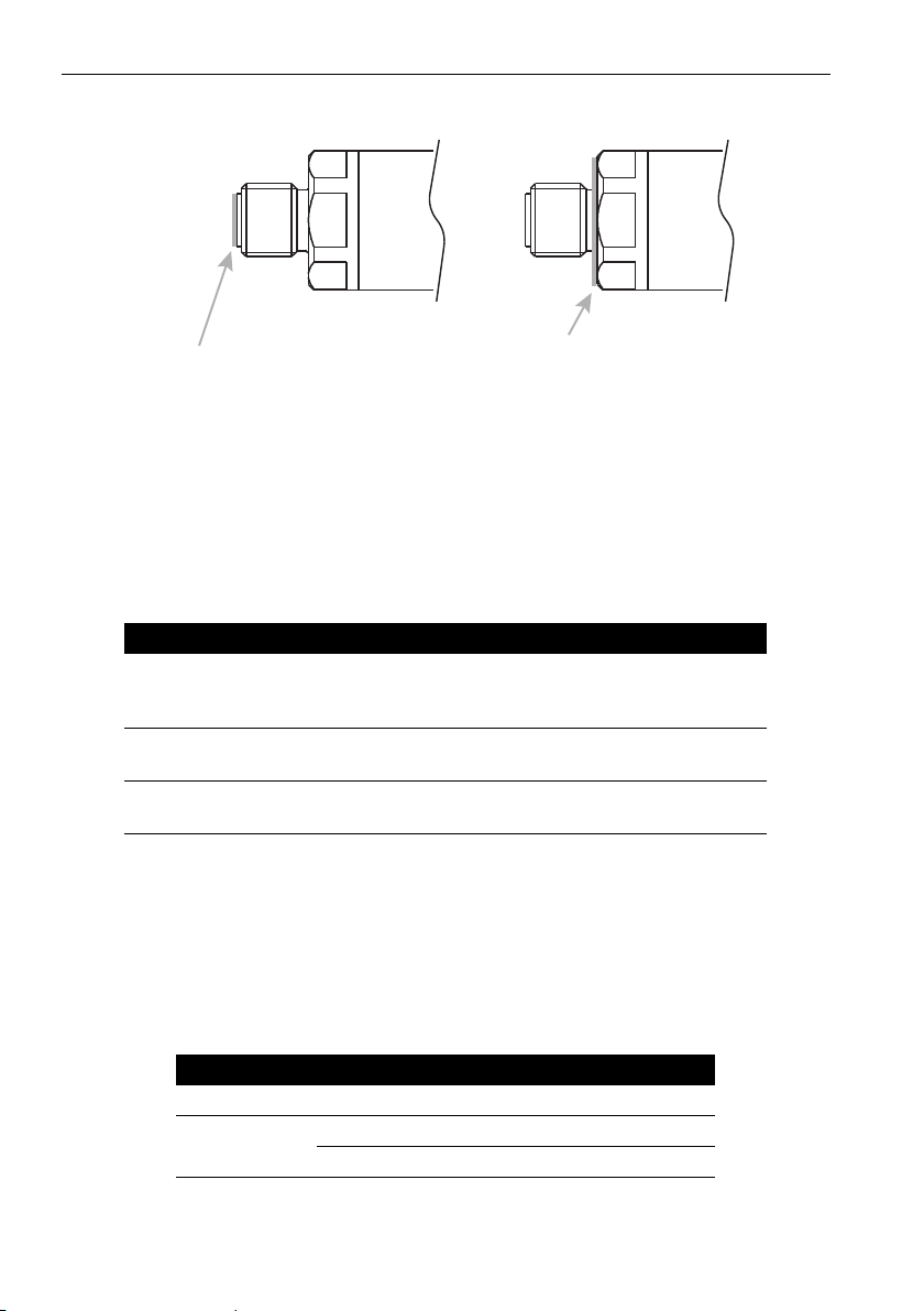
1.2 Connecting TERPS to a Pressure Source
When mounting the sensor, seal the mating surfaces. Failure to properly seal may affect
performance or calibration accuracy.