GE TX-6211-03-1 User manual

1043368C • June 2008
Copyright © 2008 GE Security
gSmoke Sensor 868 GEN2
Installation Instructions
Introduction
This is the GE Smoke Sensor 868 GEN2 Installation Instructions
for models TX-6211-03-1 and RF6211-03-1. The unit combines
a smoke sensor with an integrated fixed 135°F (57°C) tempera-
ture/rate-of-rise heat detector, and an 868 GEN2 transmitter for
use with compatible wireless control panels.
Under normal nonalarm conditions, the smoke sensor’s LED
flashes once every nine seconds while monitoring the
surrounding conditions. The smoke sensor transmits a supervi-
sory signal every 64 minutes to the panel indicating its status.
In an alarm condition due to smoke or heat, the LED changes
from flashing to on and the built-in sounder emits a temporal 3
pattern (a repeated series of three beeps followed by a short
pause). The smoke sensor also transmits an alarm signal to the
panel.
A built-in tamper switch activates whenever the smoke sensor is
removed from its mounting base, causing the smoke sensor to
transmit a tamper signal to the panel.
The smoke sensor is powered by two 3-volt lithium batteries
(included). When battery voltage gets low, the smoke sensor
transmits a low battery signal to the panel. If the batteries are not
replaced within seven days, the smoke sensor’s built-in sounder
emits a short beep or chirp every 45 seconds.
The smoke sensor also includes self-diagnostics, automatically
adjusting its sensitivity to reduce the number of required clean-
ings. When cleaning becomes necessary, the smoke sensor has a
field-replaceable optical chamber.
General guidelines
Use the following guidelines when installing the smoke sensor.
• Before mounting the smoke sensor, program (learn) the
smoke sensor into panel memory and do a sensor test from
the smoke sensor’s intended location to ensure good RF
communication to the panel.
• Locate the smoke sensor in an environmentally controlled
area where the temperature range is between 40 and 100°F
(4.4 and 37.8°C) and the humidity is between 0 and 90%
noncondensing.
• Locate the smoke sensor away from ventilation sources that
can prevent smoke from reaching the smoke sensor.
• Locate ceiling-mounted smoke sensors in the center of the
room or hallway, at least 4 in. (10 cm) away from any walls
or partitions.
• When mounting to suspended ceiling tile, the tile must be
secured with the appropriate fastener to prevent removal.
• Do not mount the smoke sensor to the metal runners of
suspended ceiling grids. The metal runners can draw the
magnet’s field away from the smoke sensor’s reed switch
causing a false tamper alarm.
• Locate wall-mounted smoke sensors so the top of the smoke
sensor is at least 4 in. (10 cm) below the ceiling, but not
more than 12 in. (31 cm).
• In rooms with sloped, peaked, or gabled ceilings, locate the
smoke sensor 3 ft. (0.9 m) down or away from the highest
point of the ceiling.
• Batteries must be installed in order to attach the smoke
sensor to the mounting base.
Locations to avoid
Do not install smoke sensors in the following locations:
• In or near areas where combustion particles are normally
present, such as kitchens, garages, near furnaces, hot water
heaters, or gas space heaters.
• On the ceiling in rooms next to kitchen where there is no
transcom between the kitchen and such rooms.
• In damp or very humid areas or next to bathrooms with
showers. Locate smoke sensors at least 5 ft. (1.5 m) away
from bathrooms.
• In very cold or very hot areas.
• In dusty, dirty, or insect infested areas.
• Near fresh air inlets or returns or excessively drafty areas.
Heating/air conditioning vents, fans, and fresh air intakes
can drive smoke away from smoke sensors.
• In dead air spaces at the top of peaked ceiling or in corners
where walls and ceiling meet. Dead air may prevent smoke
from reaching smoke sensors.
• Near florescent light fixtures. Locate smoke sensors at least
10 ft. (3 m) away from these fixtures.
Installation
To install the smoke sensor, you will need to:
• Install batteries and program the smoke sensor in the panel.
• Verify panel communication.
• Mount the smoke sensor.
Programming
To program the smoke sensor, do the following:
1. Separate the smoke sensor from the mounting base by
turning the smoke sensor counterclockwise about 15
degrees. The smoke sensor should snap off of the mounting
base.
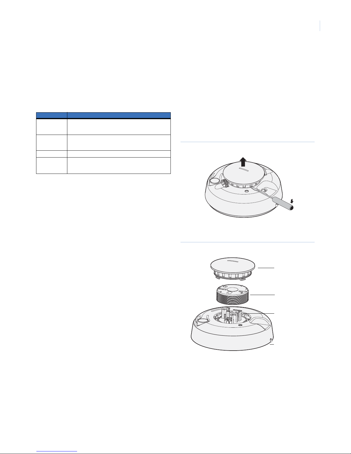
2. Slide the battery cover away from the smoke sensor to
unsnap it and lift it off (Figure 1).
Figure 1. Battery cover
3. Observing polarity, insert the two lithium batteries
(included) into the battery compartment and replace the
battery cover.
Battery cover

Smoke Sensor 868 GEN2
Installation Instructions
2
4. Attach the smoke sensor to the mounting base by lining up
the alignment tab on the smoke sensor with the alignment
arrow on the mounting base (Figure 2), then put the smoke
sensor on the base and turn it clockwise about 15 degrees.
The smoke sensor should snap into place.
Figure 2. Alignment tab and arrow
5. Make sure the system is disarmed, then put the panel into
program mode (refer to your panel documentation).
6. Proceed to the Learn/add sensors menu (refer to your panel
documentation).
7. When prompted by the panel to trip the sensor, activate the
smoke sensor tamper switch by separating the smoke sensor
from the mounting base.
8. Reattach the smoke sensor to the mounting base and exit
program mode.
Verify panel communication
Before you mount the smoke sensor, you need to verify the
smoke sensor location provides good RF communication to the
panel.
To verify panel communication, refer to your panel documenta-
tion and do the following:
1. Put the panel into sensor test mode.
2. Take the smoke sensor to the mounting location and press
and hold the smoke sensor test button for four seconds. The
smoke sensor transmits a test signal.
3. Listen for the appropriate response from system sirens.
4. Exit sensor test mode.
Mounting
Mounting hardware (screws and anchors) is included with the
smoke sensor, however you may need different hardware
depending on the installation.
To mount the smoke sensor, do the following:
1. Separate the smoke sensor from the mounting base.
2. Place the mounting base on the mounting location surface
and mark the mounting holes.
3. Secure the mounting base to the surface using appropriate
hardware.
4. Attach the smoke sensor to the mounting base.
Testing
Test the smoke sensor using the following tests:
•Sensortest
• Smoke test
• Sensitivity test
Sensor test
The sensor test verifies good communication between the panel
and the smoke sensor.
To do a sensor test, refer to your panel documentation and do the
following:
1. Put the panel into sensor test mode.
2. Press and hold the smoke sensor test button for four
seconds. The smoke sensor transmits a test signal.
3. Listen for appropriate response from system sirens.
4. Close the panel cover, if applicable.
Smoke test
The smoke test verifies that the smoke sensor activates when
detecting smoke, that the transmitted signal is received by the
panel, and that the panel reports the alarm to the central moni-
toring station.
To test the smoke sensor, do the following:
1. Contact the central monitoring station and inform them that
you are testing the system and they should not dispatch
authorities.
2. Use Smoke! in a can (part SC008) to activate the smoke
sensor. Follow the directions on the can.
3. Once activated, the transmitter LED turns on, the built-in
sounder emits a temporal 3 pattern, and the smoke sensor
transmits an alarm signal. The panel then processes the
alarm signal and reports the alarm condition to the central
monitoring station.
4. Press the smoke sensor test button to stop the built-in
sounder. The smoke sensor automatically resets when
smoke is no longer present and the LED should turn off and
return to normal operation (one flash every eight seconds).
5. Contact the central monitoring station to verify they
received the alarm report.
Be sure to alert the central monitoring station when you are
finished testing.
Tab Arrow

3
Sensitivity test
To test the smoke sensor sensitivity, do the following:
1. Press and hold the smoke sensor test button for two seconds,
then release it. The smoke sensor transmits a test signal, and
then does a self-test that causes the LED to flash one to nine
times.
2. Count the number of LED flashes, then use Table 1 to deter-
mine if any action is needed.
Fault conditions
Correct fault conditions as soon as possible. The smoke sensor
indicates a fault condition in the following ways:
• The LED stops working (no flashing or turning on) if the
smoke sensor sensitivity is not within the normal range, or if
an unserviceable hardware fault is detected.
• The smoke sensor stops transmitting supervisory signals if
the smoke sensor has an unserviceable hardware fault or is
not sensitive enough, causing the panel to indicate the
smoke sensor is in a supervisory condition. However, the
smoke sensor can still transmit alarm signals.
• The smoke sensor transmits a trouble (CleanMe) signal
when the smoke sensor is too sensitive. The panel
announces “Sensor number, name, open or fire warning”.
Battery replacement
When the battery voltage gets low, the smoke sensor transmits a
low battery signal to the panel. The panel activates trouble beeps
through system sirens and identifies the smoke sensor with the
low battery. If batteries are not replaced within seven days, the
smoke sensor’s built-in sounder emits a short beep of chirp every
45 seconds. You can silence smoke sensor chirps for 24 hours by
pressing the smoke sensor’s test button. Replace low batteries as
soon as possible. Use only 3-volt lithium batteries listed in Spec-
ifications on page 4.
To replace the batteries, do the following:
1. Remove the smoke sensor from the mounting base.
2. Slide the battery compartment cover away from the smoke
sensor to unsnap it and lift it off (Figure 1 on page 1).
3. Remove the batteries and dispose of them according to
battery directive instructions and/or instructions from local
government authorities.
4. Observing correct polarity, insert two new batteries into the
battery compartment and replace the battery cover.
5. Attach the smoke sensor to the mounting base and test the
system.
Maintenance
Clean the smoke sensor cover with a dry or damp (water) clothas
needed to keep it free from dust and dirt. When necessary, clean
the smoke sensor interior and replace the optical chamber (part
211).
To replace the optical chamber, do the following:
1. Contact the central monitoring station and inform them that
you will be doing maintenance to the system.
2. Remove the smoke sensor from the mounting base and
remove the batteries.
3. Slide a flat-bladed screwdriver in the slot on the smoke
sensor cap and gently push the handle down to pry off the
smoke sensor cap (Figure 3).
Figure 3. Removing the smoke sensor cap
4. Squeeze the optical chamber and pull it up and away from
the optical base and discard (Figure 4).
Figure 4. Optical chamber
5. Blow out or use a soft-bristled brush to remove all dust and
dirt from the optical base.
6. Line up the new optical chamber with the optical base and
snap both side of the optical chamber into place.
7. To replace the smoke sensor cap, line up the cap with the
smoke sensor, insert the cap, and turn the cap approximately
15 degrees. It should snap firmly into place.
8. Observing proper polarity, install batteries and replace the
battery cover.
9. Attach the smoke sensor to the mounting base and test
smoke sensor sensitivity.
Table 1. Sensitivity test
Flashes Indication/action
1 Unserviceable hardware fault detected. Reset the unit by
removing and replacing the batteries and retest. If error
persists, replace the unit.
2 to 3 Unit is becoming insensitive. Clean the unit. Reset the unit
by removing and replacing the batteries and retest. If error
persists, replace the unit.
4 to 7 Unit is within normal range. No action needed.
8 to 9 Unit is becoming too sensitive. Verify that the smoke
chamber is snapped down securely. Clean the unit. Replace
the optical chamber (part 211)
Smoke sensor cap
Optical chamber
Smoke sensor
Optical base

Smoke Sensor 868 GEN2
Installation Instructions
4
Note: The control panel alarm and all auxiliary functions should be
verified for a complete test of the system.
Smoke sensor limitations
Smoke sensors may not work under all conditions. Smoke
sensors cannot provide total protection of life or property and are
not a substitute for insurance. All smoke sensors are subject to
possible compromise or failure-to-warn for a variety of reasons.
For example:
• This smoke sensor will not operate and an alarm will not
sound if its batteries are dead, removed, or not installed
correctly.
• Radio signals transmitted by this smoke sensor may be
blocked or reflected by metal objects. Adjacent devices or
systems using radio frequency signals may interfere with
the operation of this smoke sensor. Test the system weekly
to ensure signals are transmitted and received properly.
• Closed or partially closed doors and distance can block or
reduce the alarm sound from this smoke sensor. This smoke
sensor is not designed for the hearing impaired.
• Smoke sensors cannot detect smoke inside chimneys, walls,
roofs, or smoke blocked by a closed door.
• Smoke sensors may not detect smoke on other levels of the
building.
• Smoke sensors may not warn in time when fires are caused
by smoking in bed, explosions, improper storage of flamma-
bles, overloaded electrical circuits, or other hazardous
conditions.
Specifications
Model number TX-6211-03-1, RF6211-03-1
RF frequency 868 MHz
Compatibility GE Security 868 GEN2 control panels/
receivers
Battery type Two 3.0 V, 1300 mAh Lithium
Recommended batteries Duracell DL 123A, Panasonic CR123A, Sanyo
CR123A
Typical standby current 35 µA
Estimated battery life Four to six years (at 20°C)
Supervisory interval 64 minutes
Typical RF output power 12 mW
Sounder (temporal pattern) 85 dBa at 3 m
Smoke sensor sensitivity 2.2% ± 1.3%/3 dm
RF immunity 20 V/m minimum, 0 to 1000 MHz
Heat detector specifications
Rate-of-rise
Fixed
15°F/min > 105°F (8.3°C/min > 40.6°C)
135°F ± 5°F) (57.2°C ± 2.8°C)
Operating temperature 40 to 100°F (4.4 to 37.8°C)
Storage temperature 4 to 167°F (-20 to 75°C)
Relative humidity range 0 to 95% noncondensing
Dimensions (L x W x H) 5.6 x 5.6 x 2.5 in. (141 x 141 x 63 mm)
Weight 288 g
Technical support
888 GE Security (888.437.3287). Toll-free in the US, Puerto Rico, and Canada.
503.885.5700 outside the toll-free area or contact your local dealer.
www.gesecurity.com
This manual suits for next models
1
Other GE Accessories manuals

GE
GE WIR-10-DR-G-D-W User manual

GE
GE ve735am User manual

GE
GE WIR-10-SR-G-D-W User manual

GE
GE MIFII GEK-106237P User manual

GE
GE BAKER HUGHES DPS 5000 Series User manual

GE
GE Monogram ZXR7510 User manual

GE
GE ZKHCSS2 User manual

GE
GE PrecisionLine RCR-90 User manual

GE
GE GDF520P DO User manual

GE
GE 19297 User manual