GE Integritas 3TL125-SACY-D10Y-P000 User manual

Document 8600092587P r04 2019 May 1
Integritas Wall Mount Charger - Quick Start Guide
Integritas™ Wall Mount 3 Rectier Battery Charger
Read and follow all safety statements, warnings, and precautions in this guide.
Basic Features:
All DC outputs are oating - not referenced to ground.
DC output Ground Fault Detection. Set at factory default adjustable at site, if necessary.
Monitored class II AC input surge device included in addition to surge capability of IP rectier units.
Monitored Class III output surge device included.
Full-featured charger control unit.
GE
Critical Power Quick Start Guide
Bottom Feed Charger with BATT & DC Load Breakers
Model number structure: 3TL125-SACY-D10Y-P000
DC output
options
Controller
options
3 Rectiers, Top/Bottom
Feed,
AC input
options
Top Feed Charger with 2 DC Breakers
Input Box
Output Box
Wall
Mount
Bracket
(top and
bottom)
IO Module
IP Rectier
slots (3)
Air Filter
Door Latch
(Lock option)
Control
Panel
DC Output
Box
Chassis
Ground
Lug
Signal Wire
Knockouts
(top and
bottom)
Controller
IO Mod-
ule slot
Controller
slot
Air Filter
IP Rectier
slots (3)
Door Latch
(Lock option)
Drip/Drop Shield
Output
Signal Unit
Output
Ground Fault
Input
Box
Output
Signal Unit
Output
Ground Fault

Integritas Wall Mount Charger - Quick Start Guide
Document 8600092587P r03 2018 August
2
Contents
Safety and Precautions ..........................................................................................................................................3
Installation...................................................................................................................................................................4
1Set External Shunt Jumper—Option...............................................................................................4
2Mount the Charger..................................................................................................................................5
2 Wall Wall Mount.............................................................................................................................5
2 Rack Rack Mount ............................................................................................................................5
3Ground the Chassis..............................................................................................................................6
4Connect AC Input..................................................................................................................................6
4A Single Phase 110/240V~ Single Phase.................................................................................7
4B Three (3) Phase 200/240V~ Three Phase............................................................................8
5Connect Loads ..........................................................................................................................................9
6Connect Batteries................................................................................................................................. 10
7Connect External Distribution (optional)................................................................................... 11
8Connect Controller Signals and Bias............................................................................................ 11
9Connect Output Signals Unit Signals ........................................................................................... 12
10 Install Rectifiers..................................................................................................................................... 13
11 Initial Start Up ........................................................................................................................................ 13
12 Configure Controller............................................................................................................................ 13
13 Apply Power to Loads ...................................................................................................................... 14
Information:
Controller - View and Change Parameters and Alarm Severity .............................................. 15
Controller - Controller - LAN Port - Local / Network.................................................................... 15
Controller Alarm Relay Jumpers........................................................................................................... 15
IP843G Controller Basic Operation...................................................................................................... 16
Battery Monitoring Connections - for use with VRLA batteries only.................................... 17
Interlock Cable Recommendations...................................................................................................... 17
Signal Connections...................................................................................................................................... 18
Alarm Outputs
Alarm Inputs
System Communications Ports
Power Units .................................................................................................................................................... 19
Maintenance ............................................................................................................................................................ 20
Troubleshooting ..................................................................................................................................................... 20
Parts List.................................................................................................................................................................... 20
Specifications & Application ............................................................................................................................. 21
Reference Documents ......................................................................................................................................... 21
Notes

Document 8600092587P r04 2019 May 3
Integritas Wall Mount Charger - Quick Start Guide
Precautions
• Install, service, and operate equipment only by professional, skilled and qualified personnel who have the necessary knowledge and
practical experience with electrical equipment and who understand the hazards that can arise when working on this type of equipment.
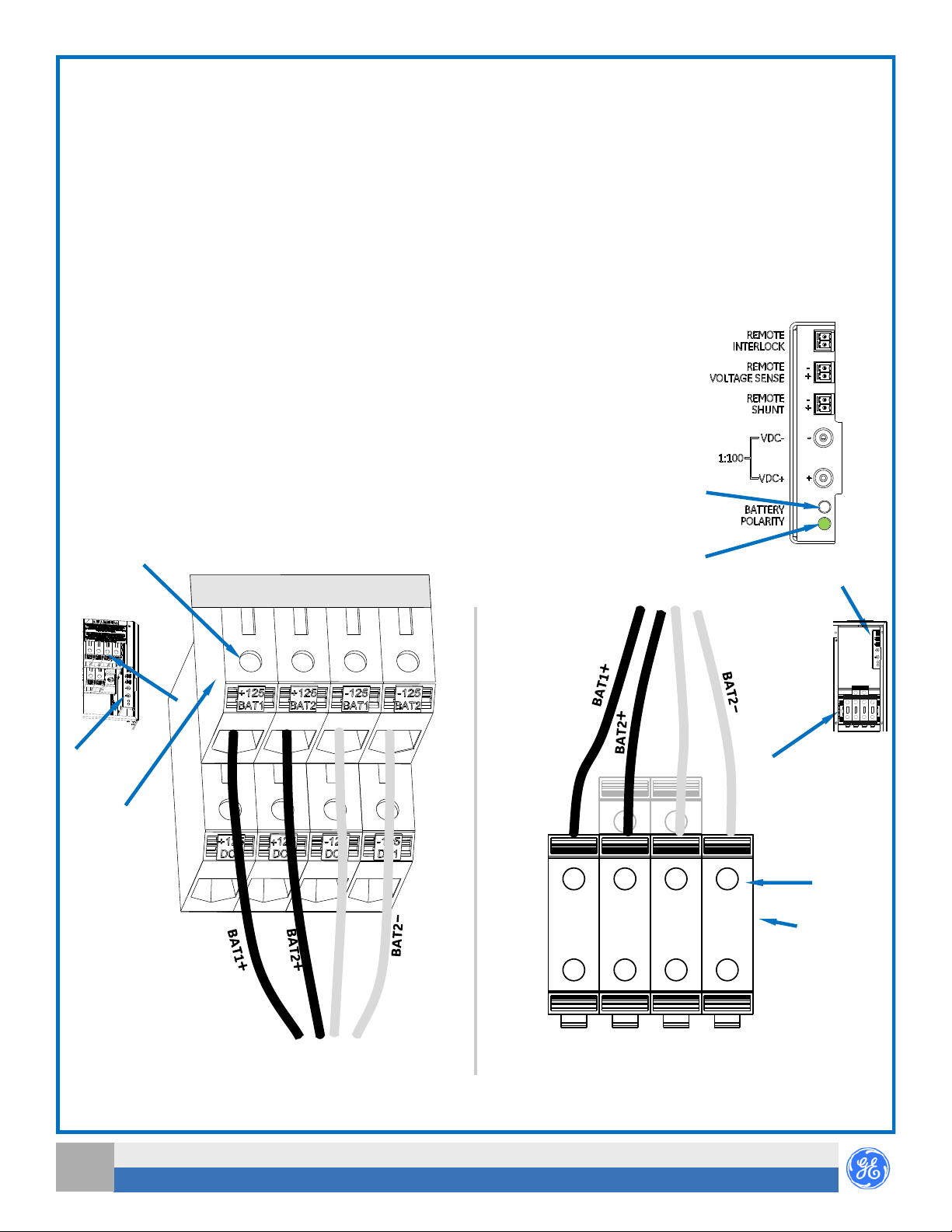
• Disconnect batteries from outputs and/or follow safety procedures while working on equipment. Batteries may be connected in parallel
with the output of the rectifiers. Turning off the rectifiers will not necessarily remove power from the bus.
• Batteries may produce explosive gas. Do not create arcs, smoke, or use an open flame in the vicinity.
• Do not disconnect permanent bonding connections unless all power inputs are disconnected.
• Verify that equipment is properly safety earth grounded before connecting power. High leakage currents may be possible.
• Exercise care and follow all safety warnings and practices when servicing this equipment. Hazardous energy and voltages are present in
the unit and on the interface cables and connectors that can shock or cause serious injury.
• Use safe lifting practices. The equipment is heavy. Lifting devices are recommended.
• Use the following precautions in addition to proper job training and safety procedures:
• Use only properly insulated tools.
• Remove all metallic objects (key chains, glasses, rings, watches, or other jewelry).
• Follow Lock Out Tag Out (LOTO) procedures: customer specified, site specific, or general as appropriate.
Disconnect all power input before servicing the equipment. Check for multiple power inputs.
• Wear safety glasses.
• Follow Personal Protective Equipment requirements: customer specified, site specific, or general as appropriate.
• Test circuits before touching.
• Be aware of potential hazards before servicing equipment.
• Identify exposed hazardous electrical potentials on connectors, wiring, etc.
• Avoid contacting circuits when removing or replacing covers;.
• Use a personal ESD strap when accessing or removing electronic components.
• Follow all warning and precautionary battery instructions, including proper replacement and disposal procedures, to minimize risk of
injury. External batteries, if applicable, are to be installed in accordance with all national and local rules and regulations, including CEC,
part 1.
• Personnel with electronic medical devices need to be aware that proximity to DC power and distribution systems, including batteries and
cables, typically found in telecommunications utility rooms, can affect medical electronic devices, such as pacemakers. Effects decrease
with distance.
Important Safety Instructions
1. SAVE THESE INSTRUCTIONS–This document contains important safety and operating instructions for the Integritas battery charger.
2. Before using battery charger, read all instructions and cautionary markings on battery charger, battery, and all connected equipment.
3. Rules and Regulations - Follow all national and local rules and regulations when making eld connections.
4. Field-wired Conductors - Follow all National Electric Code (NEC) and local rules and regulations.
a. Insulation rating: 90°C minimum; 105°C (minimum) if internal to enclosed equipment cabinets.
b. Size AC eld-wired conductors with 75°C ampacity (NEC) equal to or greater than their panel board circuit breaker rating.
c. Size DC eld-wired conductors with 90°C ampacity (NEC) equal to or greater than circuit breaker/fuse rating.
5. AC and DC input disconnect/protection - Provide accessible devices to remove input power in an emergency.
6. Compression Connectors
a. U. S. or Canada installations - use Listed/Certied compression connectors to terminate Listed/Certied eld-wire conductors.
b. All installations - apply the appropriate connector to the correct size conductor as specied by the connector manufacturer, using
only the connector manufacturers recommended or approved tooling for that connector.
7. Electrical Connection Securing: Torque to the values specied on labels or in the product documentation.
8. Cable Dress - dress to avoid damage to the conductors and undue stress on the connectors.
9. Alarm Signals - Provide external current limiting protection. Rating—V (125V for 125V charger), 0.5A unless otherwise noted.
10. Grounding - Connect the equipment chassis directly to ground.
11. WARNING: Equipment does not provide battery discharge control and protection. To be provided by external battery source.
12. WARNING: A baery can present a risk of electrical shock, burn from high short circuit current, re or explosion from vented gases.
Observe proper precauons.

Integritas Wall Mount Charger - Quick Start Guide
Document 8600092587P r03 2018 August
4
Installation
Regulations, standards, site engineering instructions, MOPs, etc. take precedence over these general installation instructions.
Step 1—Set External Shunt Jumper—ption
The charger is factory congured for an internal shunt.
Set the Shunt Jumper to External if an external shunt is used.
1. Remove charger rear panel—screws: 3 each top and bottom.
2. Move both Shunt Jumpers HDR11 and HDR12
to RMT (External) position—pins 2-3.
3. Replace charger rear panel.
Secure with 6 screws.
Tools required:
Wire cutters and strippers Torque wrench - 0-65 in-lb (0-10 Nm) Screwdrivers - Philips and Flat
Cable crimpers Sockets - etc.
Jumpers in External (RMT Positions

Document 8600092587P r04 2019 May 5
Integritas Wall Mount Charger - Quick Start Guide
Step 2—Mount the Charger
The Charger may be mounted on a wall or in a rack, in an area free of ammable/explosive materials.
Recommended Clearance: Above and Below the charger: 2 inches (5 cm), In Front of the charger: mm).
Hot air exits the top—do not locate temperature sensitive equipment above the charger.
CAUTION Use safe lifting practices. The charger is heavy—up to 154 lb (70 kg). Lifting devices are recommended.
Wall Mount—follow Step 1Wall.
Rack Mount—follow Step 1R.
Step 2 Wall—Mount the Charger to a Wall
CAUTION Use safe lifting practices. The charger is heavy. Lifting devices are recommended.
The wall and fasteners must safely support 470 lb (3 times the charger weight).
Mount with 8 sets of mounting hardware rated for at least 60 lb each.
1. Locate appropriate place for the charger.
2. Secure the bottom wall mount bracket to the wall.
a. Remove the bottom wall mount bracket from the charger—screws.
b. Drill 4 holes in the wall to mount the bottom bracket.
Use the bottom bracket as a template.
c. Secure the bottom bracket to the wall with mounting hardware.
3. Prepare to secure the top wall mount bracket to the wall.
a. Place the charger against the wall, resting on the wall mounted bottom bracket.
b. Temporarily install one screw through the bottom bracket into the charger..
c. Mark 4 holes in the wall for top bracket mounting hardware.
Use the top bracket as a template.
d. Remove the charger, rst removing the screw installed in step b.
e. Drill 4 holes in the wall to mount the top bracket.
4. Secure the charger to the wall.
a. Place the charger against the wall, resting on the bottom secured bracket.
b. Secure the top bottom bracket to the wall with mounting hardware.
c. Secure the cabinet to the bottom bracket with the 4 screws removed in step a.
Go to Step 3
Step 2 Rack—Mount the Charger to a Rack
CAUTION Use safe lifting practices. The charger is heavy. Lifting devices are recommended.
1. Attach Rack Mount Brackets positioned for ush mount or mid-mount.
Secure mounting brackets—screws each.
Torque to 25 in-lb (2.8 Nm)
2. Attach the system to the frame using a minimum of twelve (six on each side) 12-24 screws (provided).
Torque to 35 in-lb (4.0 Nm) - socket.

Integritas Wall Mount Charger - Quick Start Guide
Document 8600092587P r03 2018 August
6
Step 4—Connect AC Input
AC Input Box location: Bottom Feed—bottom left Top Feed—top left
AC knockouts: for conduit.
Danger: Shock Hazard—Turn OFF and lock-out tag-out the AC source before making AC connections.
When connecting to AC mains, follow all local and national wiring rules.
Caution: Ensure that wires do not come in contact with sharp or rough surfaces that may damage insulation and cause a short circuit.
1. Verify all AC breakers are o—Charger AC1 and external AC feed breaker.
2. Choose the next step to match AC input voltage marked on the charger ratings label.
Step 3—Ground the Chassis
Chassis Ground lug - on centers (lug provided).
Minimum 6 AWG recommended.
1. Connect ground wire to chassis on top or bottom of cabinet.
1/4-20 screws (2) provided
Torque to 65 in-lb (7.3 Nm) - socket.
Chassis Ground Lug
(top or bottom)
Screw
AC Input per Charger Label AC Input Option Follow Step
120/240 AC Step 4A Single Phase
200/240 AC Step 4B 3 Phase
Wire Entry
Ground
Wire Lug
Screw
Bottom Feed
Terminal Block for Single AC Feed shown Top Feed
Terminal Block for Single AC Feed shown
Ground
Bar

Document 8600092587P r04 2019 May 7
Integritas Wall Mount Charger - Quick Start Guide
L
Gnd
NL1
Step 4A Single Phase—Connect 120/240 Single Phase AC Input
Sizing external protectors and wire for all rectier positions (3 or 6) provides full power for all rectier positions.
1. Verify the charger AC breaker (AC1) is OFF.
2. Verify AC voltage matches AC Input per Charger Label with a meter.
3. Bring AC wires into the AC Input Box in conduit through one of the
knockouts
4. Connect Ground wire (green /green-yellow) to lug.
a. Strip (13mm)
b. Insert into ground lug.
c. Tighten lug screw securely.
d. Pull wire to verify.
5. Connect each AC wire to the terminal
block in the AC Input Box.
AC terminal connections are labeled at each
position—Gnd, L, N, L1, and L2.
a. Strip (10mm).
b. Insert into terminal block.
c. Torque screw to 13 in-lb (1.5 Nm).
d. Pull wire to verify.
Go to Step 5
Gnd
L2
Top Feed
Bottom Feed
L2
L1
Gnd
Recommended External Protection and Minimum Wire Size—6 AWG max.
120V~ Phase to Neutral
(1200W per rectifier max)
240V~ Phase to Phase
(2725W per rectifier
max)
Single-Phase Rectifiers
Rectifier Positions Powered
Maximum
Rectifiers
per Feed
External Feed
Protector
Minimum
Wire
External
Feed Protec-
tor
Mini-
mum
Wire
1 1 20A 14AWG 20A 14AWG
2 2 40A 8AWG 40A 8AWG
3 Rectifier Charger—All positions 3 60A 6AWG 60A 6AWG
240V 120V
N
L1
Gnd

Integritas Wall Mount Charger - Quick Start Guide
Document 8600092587P r03 2018 August
8
Step 4B Three (3) Phase, 3W+PE - Connect 200-240 3-Phase AC Input section
Sizing external protectors and wire for all rectier positions (3 or 6) provides full power for all rectier positions.
1. Verify the charger AC breaker (AC1) is OFF.
2. Verify AC voltage matches AC Input per Charger Label with a meter.
3. Bring AC wires into the AC Input Box in conduit through one of the
knockouts
4. Connect Ground wire (green /green-yellow) to lug.
5. Strip (13mm)
6. Insert into ground lug.
7. Tighten lug screw securely.
8. Pull wire to verify.
5. Connect each AC wire to the terminal
block in the AC Input Box.
AC terminal connections are labeled at each
position—Gnd, L, N, L1, and L2.
a. Strip (10mm).
b. Insert into terminal block.
c. Torque screw to 13 in-lb (1.5 Nm).
d. Pull wire to verify.
Go to Step 5
Top Feed
Bottom Feed
Recommended External Protection and Minimum Wire Size—6 AWG max.
200-240V~ Phase to Phase
(2725W per rectifier max)
Three (3) Phase Rectifiers
Rectifier Positions Powered
Maximum
Rectifiers
per Feed
External Feed Protector Minimum Wire
1 1 15A 14AWG
2 2 30A 10AWG
3
3
40A 8AWG
240V

Document 8600092587P r04 2019 May 9
Integritas Wall Mount Charger - Quick Start Guide
Step 5—Connect Loads (equipment to be powered)
Load voltage is marked on the charger ratings label.
Load connections are to the terminal blocks in the DC Output Box.
Load terminal block (TB) is behind the Battery terminal block.
Each TB position is marked with its connection: BAT1+, BAT1-, BAT2+, BAT2-, 125V DC+, 125V DC-, 24VDC+, 24VDC-, 48VDC+, 48VDC-.
1. Verify that equipment being powered accepts the charger output voltage.
2. Verify all DC breakers (DC1, DC2) are OFF.
3. Remove the DC Output Box cover - 4 thumbscrews.
4. Connect Load 1 Positive cable to the Positive terminal block position marked Load 1.
5. Connect Load 1 Negative cable to the Negative terminal block position behind the positive position marked Load 1.
6. If DC2 Breaker is labeled LoadRepeat from 4. for Load 2.
7. Replace the DC Output Box cover - 4 thumbscrews.
GE Shiloh Rd. Plano, TX 75074 ---Outside U.S.A. 1-972-244-9288
www.gecriticalpower.com
© 2016 General Electric Company. All rights reserved.
GE Shiloh Rd. Plano, TX 75074 ---Outside U.S.A. 1-972-244-9288
www.gecriticalpower.com
© 2016 General Electric Company. All rights reserved.
Top Feed
with 1 DC Load breaker
Bottom Feed
with 2 DC Load breakers
(Shown as –VDC)
Battery TB
Screws
Load TB
Behind
Battery TB
Screws
LOAD1+LOAD1–
Battery
BAT 1+
BAT 2+
BAT 2–
BAT 1–

Integritas Wall Mount Charger - Quick Start Guide
Document 8600092587P r03 2018 August
10
Step 6—Connect Batteries
Danger: Energy Hazard—avoid shorting battery wires to ground or to each other.
Caution: Ensure that wires do not come in contact with sharp or rough surfaces that may damage insulation and cause a short circuit.
Battery voltage is marked on the charger ratings label.
DC Output Box location: Bottom Feed—bottom right Top Feed—top right
DC knockouts: for conduit.
Wire Gauge: 6AWG to 1/0 Strip Length: mm) Torque Screw to 70 in-lb (8 Nm)
1. Measure battery voltage and polarity with a meter.
2. Verify all DC breakers (DC1 and DC2 / BATT if present) are OFF.
3. Remove the DC Output Box cover - 4 thumbscrews.
4. Connect Battery Positive cable to the terminal block position marked BAT1+ (BAT2+ for second battery).
5. Connect Battery Negative cable to the terminal block position marked BAT1– (BAT2– for second
battery).
6. Repeat from 1 for second battery if present.
7. Turn BATT breaker ON if present.
8. Verify the Reverse Polarity LED is not Red and the Ready LED is Green.
If the Reverse Polarity LED is RED, reverse battery cables.
If Ready LED is not Green, verify the voltage on the battery wires.
9. Turn BATT breaker OFF if present.
Top Feed
with 1 DC Load breaker
Bottom Feed
with 2 DC Load breakers
(Shown with +/- 125VDC)
Battery TB
Screws
Screws
Battery TB
Reverse
Polarity LED
Ready LED
Output Signal Unit
Output Sig-
nal Unit
BAT1-
BAT1–
BAT 1+
BAT 2+
BAT 2–
BAT 1–

Document 8600092587P r04 2019 May 11
Integritas Wall Mount Charger - Quick Start Guide
Step 8 - Connect IO Module Signals and Bias
Connect per site engineering instructions.
Connections are on the front of the IO Module connections unit.
Route wires through routing bend tab and tie wires to wire tie points and wire as desired.
TB1—TB21 detachable block - Strip - mm) Torque - 2 in-lb (0.25 Nm)
Alarm Outputs and Inputs
TB1—TB10 Alarms Outputs - Wire to oce alarms. See Information: Signal Connections.
TB11—TB20 Inputs - Wire to signal sources. See Information: Signal Connections.
Alt Bias
TB21 Alternative 24V external Bias supply
LAN
LAN Ethernet LAN or local PC connection
1-Wire Battery Temp and Voltage Monitor - Optional
1-WIRE DATA See Information: Battery Monitoring Connections.
IP843G IO Module
Step 7—Connect External Distribution—future option
ALARM OUTPUTS
RATED 125VDC @ 0.5A
REF FACTORY DEFAULT ASSIGNMENT (SIGNAL – PIN#1; COMMON – PIN2)
TB1 CRITICAL ALARM
TB2 MAJOR ALARM (CHARGER SUMMARY)
TB3 MINOR ALARM
TB4 R1 (RECTIFIER FAIL –RFA/MRFA)
TB5 R2 (AC FAIL –ACF/MACF)
TB6 R3 (LOW VOLTAGE –BD/VLV)
TB7 R4 (GROUND FAULT –GFI)
TB8 R5 (SURGE PROTECTOR –SPD)
TB9 R6 (HIGH VOLTAGE –HVSD/HV)
TB10 R7 (CHECK BATTERY)
TB11 AUX1 (AIR CONDITIONER FAIL)
ALARM INPUTS
(“DRY”, NO VOLTAGE, BINDARY CONTACT MONITORS)
TB12 AUX2 (DOOR OPEN)
TB13 AUX3 (HIGH EXTERNAL AMBIENT)
TB14 AUX4 (LOW EXTERNAL AMBIENT)
TB15 CHARGER/PLANT BATTERY TEST (PBT)
TB16 REMOTE RECTIFIER STANDBY (GSTBY)
TB17 AUX9 (AUXILIARY 9)
TB18 AUX8 (AUXILIARY 8)
TB19 OSA1 –(OPENSRING)
TB20 AUX6 (HYDROGEN PRESENT)
DIGITAL PORTS
TB21 RESERVED FOR FUTURE USE
TB22 1-WIRE TEMP PROBES; 1-WIRE SIGNAL ON PIN1; RETURN ON PIN2
TB24
OPTIONAL #24VDC CONTROLLER BACK-BIAS INPUT
ALT-BIAS 24VDC-IN PIN 4; ALT-BIAS 24VDC-IN RTN PIN 5
RECT DATA RS485 / GALAXY PROTOCOL RECTIFIER SERIAL BUS
LAN 10/100 BASE-T ETHERNET

Integritas Wall Mount Charger - Quick Start Guide
Document 8600092587P r03 2018 August
12
Step 9 - Connect Output Signals Unit Signals
Connect per site engineering instructions.
Connections are on the front of the Output Signals Unit. In the DC Output Box
Detachable blocks - 16 AWG max Strip - mm) Torque - 2 in-lb (0.25 Nm)
Route wires through routing bend tab and tie wires to wire tie points and wire as desired.
External Shunt—optional
Jumper on rear of charger must have been moved in Step 1.
Connect with polarity as marked.
Remote Voltage Sense—optional
1. Install current limiting module at the battery.
Battery Module
125V 847540424
24/48V 848738278
a. Extend wires with butt splices (not provided).
b. Connect to battery + and—posts (terminals not provided).
Stack up: Battery Post, Power terminal, Remote Voltage Sense terminal.
c. Torque per battery specication.
2. Connect current limiting module to the signal unit Remote Voltage Sense detachable block with polarity as marked.
Extend wires with butt splices (not provided).
Remote Interlock—optional
A factory installed jumper enables the rectiers without an external signal.
Interlock enables rectier output.
Enable rectier output with between pins of Remote Interlock connector.
Open Circuit voltage - 7Vdc. Short circuit current - 1mA per shelf. Max enable voltage - 0.7Vdc.
Cables not provided—see Information Interlock Cable Recommendations.
1. Remove factory installed jumper from Remote Interlock connector.
2. Insert interlock signal cable into Remote Interlock connector.
Output Signal UnitDC Output Box
Bottom Feed shown
To Remote
Voltage Sense
Current Limiting
Module

Document 8600092587P r04 2019 May 13
Integritas Wall Mount Charger - Quick Start Guide
Step 11—Initial Start-up
Rectiers are keyed allowing only their installation into chargers of the same voltage.
1. Verify that AC and DC connections are complete and secure.
2. Turn on AC input breakers.
a. External feed breaker(s)
b. Charger AC breaker(s) (AC1 and AC2 if present)
Rectiers will start-up. Then the Controller will start-up.
3. Verify
4. All rectiers should be indicating green AC and DC LEDs with no red LEDs.
The Controller should be indicating no alarms—display background should be green and no red LEDs.
If alarms are present, see Troubleshooting section.
If there are no alarms, make required adjustments to the default settings on the controller for this installation.
Step 10—Install Rectiers
Rectiers are keyed for input and output voltage, allowing only their installation into compatible chargers .
Warning: Equipment Damage—Do not Install rectiers if the Reverse Polarity LED is Red .
1. Verify the Reverse Polarity LED is not Red and the Ready LED is Green.
If the Reverse Polarity LED is RED, reverse battery cables.
If Ready LED is not Green, verify the voltage on the battery wires
2. Slide Rectier rmly into a Rectier position - oriented as shown.
3. Secure Rectier—thumb screws—top and bottom.
4. Repeat for remaining Rectifiers.
5. Secure empty slot fillers in each vacant Rectifier position—thumb screws top and bottom.
Step 12 - Congure Controller
Verify and edit controller basic configuration parameters per site engineering instructions.
See Information: IP843G Controller Basic Operation.
IP843G Product Manual provides additional detail.

Integritas Wall Mount Charger - Quick Start Guide
Document 8600092587P r03 2018 August
14
Step 13—Apply Power to Loads and Batteries Connected through Breakers
Rectiers are keyed allowing only their installation into chargers of the same voltage.
1. Turn on BATT breaker if present)
2. Verify DC output voltage with a meter on VDC+ and VDC–jacks on the Output Signal Unit.
Terminals voltage is output voltage ÷100.
3. Turn on load breaker(s) DC1 (and DC2 if present)
4. Verify No Ground Fault alarm—Ground Fault Unit U LED is Green and F LED NOT Red.
If F LED is Red, adjust values of resistance threshold down (R1 + R2).
Operate Test/Reset button after each adjustment.
If alarm continues, trouble shoot load and battery wiring accordingly.
Output Ground Fault Unit
LEDs
R1 & R2
Test/Reset Button
Output Ground Fault Unit
Bottom Feed shown
Output Signal Unit

Document 8600092587P r04 2019 May 15
Integritas Wall Mount Charger - Quick Start Guide
Information: Controller Alarm Relay Jumpers
Jumpers are located on the side top of the controller.
Alarm Relay Jumper Factory Defaults are Open On Alarm.
1. Remove Controller - 2 thumb screws.
2. Position jumpers per site engineering instructions
3. Replace controller - secure with 2 thumb screws.
Information: Controller - LAN Port - Local / Network
The LAN port is be congured as Local or Network -
controller display menu path Conguration > Communication Ports > Network Settings > DHCP > mode CLIENT or SERVER
Local (Server): LAN connects to a laptop.
Local (Server) is a temporary setting. When configuration is complete, return LAN port to Network (Client) mode.
Network (Client): LAN connects to a network. (Default).
CAUTION: Do not connect LAN port to a network when configured as Local.
See Pulsar Plus G3 Controller Product Manual for details.
Information: Controller - View and Change Parameters and Alarm Severity
View and change system parameters and alarm severity
from the factory defaults via:
A. Front Display
B. LAN port in Local mode via a laptop (web pages)
C. LAN port in Network mode (web pages)
D. Craft Port via laptop and EasyView2 software or HyperTerminal.
EasyView2 (GUI) software can be downloaded from www.gecriticalpower.com.
See Pulsar Plus G3 Controller Product Manual for details.

Integritas Wall Mount Charger - Quick Start Guide
Document 8600092587P r03 2018 August
16
Information: IP843G Controller Basic Operation
View and change system parameters from the factory defaults via
A. Controller Display
B. Craft Port on front of controller using a laptop with EasyView2 software or HyperTerminal.
EasyView2 (GUI) software can be downloaded from www.gecriticalpower.com,
C. J5 LAN port web pages using a laptop with browser. LAN port Server mode is for local laptop connection. Set the LAN port to Server:
With the controller set to Server enter the default IP address 192.168.2.1 (default) in the web browser address eld.
Warning: Do not connect J5 LAN port to a network when set to Server. Set the controller to Client or Static before connecting to the
network. Static is the factory default setting and the typical setting for most networks.
Controller Alarm Status: The display changes colors; Green = Normal, Amber = Minor Alarm, Red = Critical/Major Alarm
Some alarms may occur during initial installation; example: thermal probe fail or Major/Minor communication fail .
Clear these alarms: Via Controller Display: follow the menu path; Menu > Control/Operation > Clear Events or Uninstall Equipment.
Via web pages or EasyView2; Select the Maintenance tab > clear latched events and clear missing devices.
Verify Basic Installation Settings: Date, Time, Battery Type, number of strings and oat voltage
Controller Display - Menu > Conguration > System Settings and Menu > Conguration > Batteries.
Web pages or EasyView2 -Installation Tab for Date, Time. Site ID and Site Description.
Settings Tab > Battery Management for Battery Type and number of battery strings installed.
Front Display
Menu Map
Web Home Page
Control Panel
Status LEDs
Menu
Navigation
LCD
Display

Document 8600092587P r04 2019 May 17
Integritas Wall Mount Charger - Quick Start Guide
Information: Battery Monitoring Connections - for use with NiCd and Lead acid batteries (VRLA, Flooded)
Battery Monitoring is accomplished with a Daisy Chainedseries of probes. The Probes monitor battery temperature. Bolt the Probe under
the –terminal connector hardware; NOT under the connecting lug.
Max per system: Probes - 16.
Battery Temperature Measurement
Ordering Codes Descriptions Ordering
Codes Descriptions
1600093513A DTP873-Battery Thermal Probe
1600093512A DTP873-Ambient Probe
Information Interlock Cable Recommendations
• Wire - 20-24 AWG
• Mating Connector: Molex housing - 43025- 0200,
• Terminals - Molex 43030-0008 (15µgold plated)
• Hand Crimp Tool - Molex 0638190000
• Insertion Tool - Molex 0638120800
• Extraction Tool - Molex 0011030043

Integritas Wall Mount Charger - Quick Start Guide
Document 8600092587P r03 2018 August
18
Information: Signal Connections.
Alarm Relays Factory set to Open On Alarm. Rated 125V (60V for 24V and 48V chargers), 0.5A.
“Dry” No Voltage Binary Inputs Require a contact closure to Common (pin 2).
“Dry” 24V Biased Binary inputs Require a contact closure to 24V Source (pin 2).
Alarm Outputs
Connector Description—Signal on Pin 1 Pin 2
TB1 Power Critical Alarm Common
TB2 Power Major Alarm Common
TB3 Power Minor Alarm Common
TB4 Alarm R1 (default is RFA/MRFA) Common
TB5 Alarm R2 (default is ACFMACF) Common
TB6 Alarm R3 (default is BD/VLV) Common
TB7 Alarm R4 (default is GFI) Common
TB8 Alarm R5 (default is SPD, DC, and AC) Common
TB9 Alarm R6 (default is BTA “Battery Test Active”) Common
TB10 Alarm R7 (default is “Check Battery”) Common
Alarm Inputs
Connector Description—Signal on Pin 1 Pin 2
TB11
(IN007) “Dry” No Voltage Binary contact input (default is AUX1 “Air Conditioner Fail”) No Voltage Re-
turn
TB12
(IN008) “Dry” No Voltage Binary contact input (default is AUX2 “Door Open”) No Voltage Re-
turn
TB13
(IN009) “Dry” No Voltage Binary contact input (default AUX3 “High External Ambient”) No Voltage Re-
turn
TB14
(IN010) “Dry” No Voltage Binary contact input (default AUX4 “Low External Ambient”) No Voltage Re-
turn
TB15
(IN006) “Dry” No Voltage Binary contact input (default “Plant Battery Test (PBT)”) No Voltage Re-
turn
TB16
(IN005)
“Dry” No Voltage Binary contact input (default “Remote Rectifier Standby/Emergency Power
Off”)
No Voltage Re-
turn
TB17
(IN001) “Dry” 24V Biased Binary contact input 24V Source (default “AUX9 Auxiliary 9”) 24V Source
TB18
(IN002) “Dry” 24V Biased Binary contact input (default AUX8, “Auxiliary 8”) 24V Source
TB19
(IN004) “Dry” 24V Biased Binary contact input 24V Source (default OSA1, “Open String”) 24V Source
TB20
(IN003) “Dry” 24V Biased Binary contact input (default AUX6, “Hydrogen Present”) 24V Source
TB21 +24V Alternative external 24VDC back bias input for controller. +24V DC Return
System Communications Ports
Connector Description—Signal on Pin 1 Pin 2
RECT DATA Connection to isolated rectifier RS485 Galaxy protocol serial bus. not applicable
1-WIRE DA-
TA Connection to 1-Wire temperature probes. 1-Wire signal on pin 1. 1-Wire Return

Document 8600092587P r04 2019 May 19
Integritas Wall Mount Charger - Quick Start Guide
Information: Power Units
Rectiers—single-phase
Rectier Input V AC
Option
Output DC
Voltage Power
gray
IP020ACR125ATEZ
125Vdc
200-277 Vac AC, L3, LW, HW 125Vdc 2500W
100-120 Vac AC, LW 125Vdc 1280W
blue
IP050ACR048ATEZ
48Vdc
200-277 Vac AC, L3, LW, HW 48Vdc 2725W
100-120 Vac AC, LW 48Vdc 1200W
orange
IP100ARC024ATEZ
24Vdc
200-277 Vac AC, L3, LW, HW 24Vdc 2725W
100-120 Vac AC, LW 24Vdc 1200W
Rectier LEDs
Power Unit LEDs (see Troubleshooting for details)
LED Description
Norm Normal—Green
ACF AC Input Failure—Red
Fail Failure—Red
RP Reverse Polarity Failure—Red
Web Home Page

Integritas Wall Mount Charger - Quick Start Guide
Document 8600092587P r03 2018 August
20
Maintenance—Air Filters
Air Filters should be washed or replaced at intervals determined by the installation environment—dusty environments require more fre-
quent service.
Air lters may be washed and reused.
1. Remove air lter carrier—thumb screws.
2. Remove and replace air lter.
Air lter slides out to the rear of the air lter carrier.
3. Replace air lter carrier with lter—secure with 2 thumb screws.
Filter Washing
1. Wash lter in soap water.
2. Gently wring out by hand.
3. Air dry for at least 24 hours before installing into lter carrier.
Troubleshooting
Troubleshooting tables are in the Pulsar Plus Controller Family Troubleshooting Table document.
Parts List
continued on next page
Power Modules
Comcode Description Application
150050531 IP020ACR125ATEZ 125VDC Hot-Swappable Integritas Charger Module, Single Phase 120 -
277AC Input, 20A Output
150050530 IP050ACR048ATEZ 48VDC Hot-Swappable Integritas Charger Module, Single Phase 120 -
277AC Input, 50A Output
150052733 IP100ACR024ATEZ 24VDC Hot-Swappable Integritas Charger Module, Single Phase 120 -
277AC Input, 100A Output
8600092348P Blank IP Charger Module Faceplate Blank ller for empty charger slots
Controller Modules
Comcode Description Application
1600093508A IP843G_24V_S CONTROLLER MODULE Integritas Wall Charger, Hot- Swappable 24VDC Controller Module with
secure protocols
1600093510A IP843G_48V_S CONTROLLER MODULE Integritas Wall Charger, Hot- Swappable 48VDC Controller Module with
secure protocols
1600093509A IP843G_125V_S CONTROLLER MODULE Integritas Wall Charger, Hot- Swappable 125VDC Controller Module with
secure protocols
1600093511A IP843G_IO MODULE Integritas Wall Charger, Input / Output Module (Compatible with all
charger voltages)
Table of contents
Other GE Batteries Charger manuals
Popular Batteries Charger manuals by other brands

Energic Plus
Energic Plus RE Series user manual

Nikon
Nikon MH-61 instruction manual

Digital Works
Digital Works ReZap Pro RBC889 Use & care guide

Monacor
Monacor JTS TG-10CH2 manual

National Railway Supply
National Railway Supply ELC-24/10-M-D Installing, operating and service instructions

impact
impact VE-TTLCH instructions