GE Profile JP350AAAA User manual

1
Before you begin—Read these instructions completely and carefully.
IMPORTANT—Save these instructions for local inspector’s use.
IMPORTANT—OBSERVE ALL GOVERNING CODES AND ORDINANCES.
Note to Installer—Be sure to leave these instructions with the Consumer.
OWNER—Keep these instructions for future reference.
Note—This appliance must be properly grounded.
INSTALLATION INSTRUCTIONS FOR YOUR NEW
30" ELECTRIC COOKTOP
FOR YOUR SAFETY TOOL LIST
• 1/8" drill bit
• Electric or hand drill
• Flat bladed screwdriver
• Pencil
• Ruler or tape measure and straightedge
• Hand or saber saw
ELECTRICAL REQUIREMENTS
Thisappliancemustbesuppliedwiththepropervoltage
andfrequency,andconnectedtoanindividual,properly
groundedbranchcircuit,protectedbyacircuitbreaker
or time delay fuse, as noted on rating plate.
Wiring must conform to National Electrical Codes. You
can get a copy of the National Electrical Code, ANSI/
NFPA No. 70-Latest Edition by writing:
National Fire Protection Association
Batterymarch Park
Quincy, MA 02269
We recommend that you have the electrical wiring and
hookup of your counter unit done by a qualified
electrician. After installation, have the electrician show
you where your main disconnect is located.
Therangeconnectorblockisapprovedforcopperwire
connection only, and if you have aluminum house
wiring, you must use special UL approved connectors
for joining copper to aluminum.
You must use a three-wire, A.C. 208Y/120Volt or 120/
240 Volt, 60 Hertz electrical system. A white (neutral)
wire is not needed for this unit.
Refer to the rating plate on your unit for the K.W. rating
for your counter unit.
SR10239
Pub. No. 31-10147
229C4053P018-4
STOP!
CAUTION:
For Personal Safety remove house
fuse or open circuit breaker before
beginning installation. Failure to do
so could result in serious injury or
even death.
•Be sure your cooktop is installed properly by a
qualified installer or service technician.
•Toeliminatetheriskofburnsorfirebyreachingover
heated surface elements, cabinet storage located
above the surface units should be avoided. If
cabinetstoragespaceistobeprovided,theriskcan
be reduced by installing a range hood that projects
horizontally a minimum of 5" beyond the bottom of
thecabinets. Cabinetinstallation abovethecounter
unit may be no deeper than 13".
•The cooktop should be easy to reach and lighted
with natural light during the day.
•Always disconnect the electrical service to the unit
before repairing or servicing the counter unit. This
can be done by disconnecting the fuse or circuit
breaker. Failure to do this could result in a
dangerous or fatal shock. Know where your main
disconnect switch is located. If you don’t know,
have your electrician show you.

2
PREPARING THE OPENING
ThefollowingMINIMUMclearancedimensionsmustbe
maintained:
•To insure accuracy, it is best to make a template
whencuttingtheopeninginthecounter. SeeFigure
2 for all necessary dimensions.
•Thirtyinches(30")minimumverticalclearancefromthe
cooktoptothenearestunprotectedoverheadsurface.
•Oneand one half inches (1 1/2") minimumon the right
andtwoandonehalfinches(21/2")minimumclearance
on the left from counter unit to side wall to a height of
eighteen inches (18").
•Makesurethewallcoverings,countertopandcabinets
around the range can withstand heat (up to 200
°
F)
generated by the range, oven or cooktop.
Fig. 1
Fig. 2
2 1/2" MIN.
clearance from
cutout to side
wall on the left
of the unit
30" MIN.
clearance from
countertop to
overhead surface
1 1/2" MIN.
clearance from
cutout to side
wall on the right
of the unit
13" MAX. Depth
of unprotected
overhead cabinets
18" MIN.
height from
countertop to
nearest cabinet on
either side of unit
•(1 3/4") between counter unit rear edge and wall
behind unit.
•(2 1/2") between front edge of counter unit and the
front edge of the counter.
•Fiveinches(5")minimumverticalclearancebetween
the cooktop bottom and any combustible surface.
19 3/8" 28 1/2"
20 1/2"
29 1/2"
28 1/2"
*
3 3/8"
1 3/4"
2 1/2" MIN.
19 5/8"
COOKTOP
*NOTE: Depth of the unit at the conduit location
(right rear) is 4 3/4".
INSTALLATION
STOP!
IMPORTANT:
Remove all packing
material and literature from the
cooktop before connecting any
electrical supplies.
Beforeinstallingthecounterunitormovingittoanother
location, have the electrician verify:
•Thatyourhomeisprovidedwithadequateelectrical
service.
•Thattheadditionofthecounterunitwillnotoverload
the household circuit on which it is used.
Install an approved junction box where it will be easily
reached through the front of the cabinet where the
counterunitwillbelocated. Thecounterunithas3feet
of conduit.

3
Fig. 3
BE SURE THIS CUT DOES NOT
INTERFERE WITH CABINET
STRUCTURE AT FRONT
16" MIN.
(40.6 CM)
BE SURE THIS CUT DOES NOT INTERFERE
WITH CABINET STRUCTURE AT FRONT
IMPORTANT:Thejunctionboxmustbelocated
where it will allow considerable slack in the
conduit for serviceability. See Figure 3.
16" MIN.
SUGGESTED MOUNTING OF AN APPROVED
JUNCTION BOX
(NOT FURNISHED WITH UNIT)
Install the counter unit in the cutout opening.
NOTE: If the unit is being installed in a blind
counter(onewithnocabinetopeningbelow),
wire connections must be made before
putting the unit into the cutout.
INSTALLINGINASTANDARDORTILE
COUNTER:
Toattach theunitto astandardcounter, insertthehold
down bracket in the slots on each side of the unit. Use
thescrewsprovidedtoattachtheunittothecounteras
shown.
HOLD DOWN
BRACKET
MOUNTING
SLOT
BURNER BOX
SIDES
USE SUITABLE
FASTENERS FOR
ANCHORING IN
CABINET SIDES
CABINET
SIDES
Fig. 4
ELECTRICAL CONNECTIONS
STOP!
The electrical power to the counter
unit supply line must be shut off
while line connections are being
made. Failure to do so could result
in serious injury or death.
When making the wire connections, use the entire
lengthofconduitprovided(3feet). Theconduitmustnot
be cut.
Connect the red and black leads from the counter unit
conduit to the corresponding leads in the junction box.
Thebare ground wire in the conduit is connected to the
counter unit frame. When connecting to a 3-conductor
branch circuit, if local codes permit, connect the bare
groundconnectorleadoftherangetothebranchcircuit
neutral (gray or white in color).
SPECIAL GROUNDING INSTRUCTIONS
• When connecting to a 4-conductor branch circuit;
•When local codes do not permit grounding through
neutral;
• When installing counter unit in a mobile home:
Attach the appliance grounding lead (green or bare
copper) to the residence grounding conductor (green
or bare copper) in accordance with local codes.

BE SURE THIS CUT DOES NOT
INTERFERE WITH CABINET
STRUCTURE AT FRONT
16" MIN.
(40.6 CM)
— Printed in LaFayette, Georgia —
100% Recycled Paper
Printed LaFayette, Georgia
Recycled Paper
NOTE TO ELECTRICIAN:
Thepowerleads suppliedwith thisappliance
are U.L. recognized for connection to larger
gauge household wiring. The insulation of
these leads is rated at temperatures much
higher than the temperature rating of
household wiring. The current carrying
capacity of a conductor is governed by the
wire gauge and also the temperature rating
of the insulation around the wire.
NOTE: ALUMINUM WIRING
A. WARNING:
IMPROPER CONNECTION OF ALUMINUM
HOUSE WIRING TO THE COPPER LEADS
CAN RESULT IN A SERIOUS PROBLEM.
B. Splicecopper wiresto aluminumwiring
using special connectors designed and
U.L. approved for joining copper to
aluminum and follow the manufacturer’s
recommended connector procedure
closely.
NOTE: Wire used, location and enclosure of
splices, etc., must conform to good wiring
practice and local codes.
SUGGESTED MOUNTING OF AN APPROVED
JUNCTION BOX
(NOT FURNISHED WITH UNIT)
16" MIN.
Fig. 5
BE SURE THIS CUT DOES NOT INTERFERE
WITH CABINET STRUCTURE AT FRONT
4
SR10239
Pub. No. 31-10147
229C4053P018-4

Antes de empezar—Lea estas instrucciones completa y cuidadosamente.
IMPORTANTE—Guarde estas instrucciones para el uso del inspector local.
IMPORTANTE—OBSERVE TODOS LOS CODIGOS Y ORDENANZAS VIGENTES.
Nota al Instalador—Cerciórese de dejar estas instrucciones con el consumidor.
DUEÑO—Guarde estas instrucciones para referencia futura.
Nota—Este aparato electrodoméstico tiene que hacer tierra adecuadamente.
CUBIERTA DE COCINAR ELECTRICA DE 30"
INSTRUCCIONES DE INSTALACION PARA SU NUEVA
PARA SU SEGURIDAD LISTA DE HERRAMIENTAS
•Taladro de punta de 1/8"
•Taladro eléctrico o manual
•Atornillador de cabeza plana
• Lápiz
• Regla
• Sierra de mano o eléctrica
REQUERIMIENTOS ELECTRICOS
Este aparato debe ser alimentado con el voltage y la
frecuencia adecuada, y conectado a una rama del
circuíto que sea individual y que haga tierra
adecuadamente,queestéprotegidaporuninterruptor
de circuíto o un fusible de tiempo demorado, como se
instruye en la tabla de valores.
El alambrado debe estar de acuerdo con los Códigos
EléctricosNacionales(NationalElectricCodes). Usted
puedeconseguirunacopiadeNationalElectricCodes,
ANSI/NFPA No 70 Latest Edition (Ultima Edición)
escribiendo a:
National Fire Protection Association
Batterymarch Park
Quincy, MA 02269
Recomendamos que el alambrado y las conexiones
eléctricasde su unidad de mesón seanhechas por un
electricista competente. Después de la instalación,
pídale al electricista que le muestre donde está el
interruptor desconectador principal.
El bloque de conexiones de la estufa está aprobado
paraconexionesdecobresolamente,ysielalambrado
de su casa es de aluminio, usted tiene que usar
conectores UL aprobados especiales para juntar el
cobre al aluminio.
Usteddebeusarunsistemaeléctricodetresalambres,
C.A. 208Y/120 Voltios 120/240 Voltios, 60 Hertz. Un
alambre blanco (neutral) no es necesario para esta
unidad. Si no se usa, el alambre blanco que viene de
la fuente eléctrica de la casa se puede cubrir con una
cinta y terminar en la caja de conexiones.
Consulte la tabla de valores en su unidad para el valor
K.W. de su unidad.
1
STOP!
PRECAUCION:
Para seguridad personal, saque el
fusible de la casa o abra el circuito
desconectador antes de empezar la
instalación.
•Asegúrese de que su cubierta de cocinar esté
correctamente instalada por un instalador
competente o un técnico de servicio.
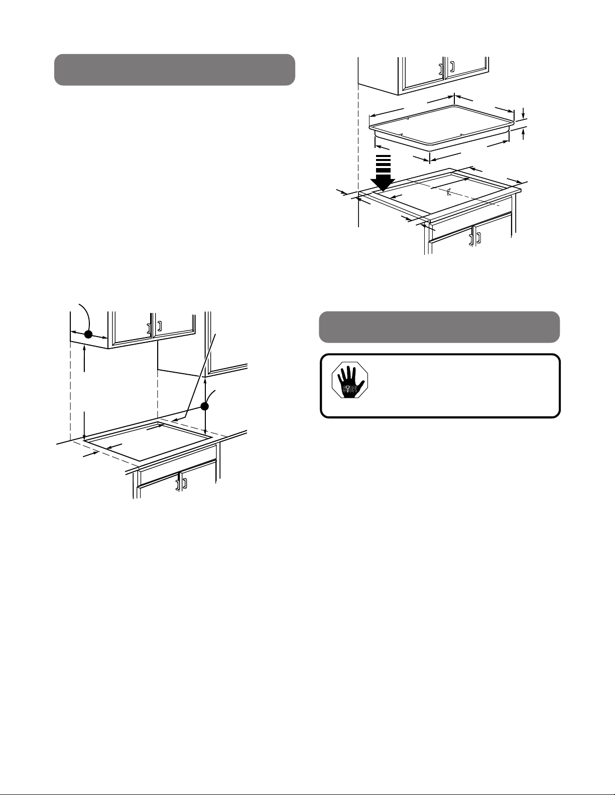
•Para eliminar el riesgo de quemaduras o fuego
tratando de tomar algo por sobre los elementos de
superficiecalientes,deberíaevitartenergabinetes
de almacenamiento arriba de las unidades de la
superficie. Si tiene gabinetes de almacenamiento,
elriesgosepuedereducirinstalandounacampana
de estufa que se proyecte horizontalmente un
mínimo de 5" más allá de la base de los gabinetes.
Lainstalacióndelosgabinetessobrela unidad del
mesónnodeberíatenermásde13"deprofundidad.
•La cubierta de cocinar debe ser de acceso fácil y
alumbrada con luz natural durante el día.
•Siempredesconectelafuentedeelectricidaddela
unidadantesdeunareparaciónodeunserviciode
la cubierta de cocinar. Esto se puede hacer
desconectandoelfusibleoelinterruptordelcircuíto
Si esto no se hace, podría resultar en un golpe
eléctrico peligroso o fatal. Sepa donde está el
interruptor principal. Si no lo sabe, haga que el
electricista se lo muestre.
SR10239
Pub. No. 31-10147
229C4053P018-4

2
PREPARE LA ABERTURA
Se deben mantener las siguientes dimensiones
MINIMAS de espacio:
•Paraasegurarlaexactitud,esmejorhacerunpatrón
cuando haga el corte en el mesón. Vea la figura 2
para todas las dimensiones necesarias.
•Treinta pulgadas (30") mínimo de espacio vertical
desde la cubierta de cocinar hasta la superficie de
arriba sin protección más cercana.
•Una y media pulgada (1 1/2") mínimo de espacio a
la derecha y dos y media pulgadas (2 1/2") mínimo
deespacioalaizquierdadesdelaunidaddemesón
alasmurallasdelosladosyunaalturadedieciocho
pulgadas (18").
•CercIóresede quelos revestimientos dela muralla,
mesón y gabinetes pueden soportar el calor
generado por la estufa, horno y cubierta, hasta
200
°
F.
2 1/2" MIN.
de espacio
desde el hoyo
a la pared del
lado izquierdo
de la unidad
30" MIN.
de espacio desde
la superficie del
mesón hasta la
superficie de
arriba.
1 1/2" MIN.
de espacio desde
el hoyo a la pared
del lado derecho
de la unidad
13" MAX. profundidad
de los gabinetes sin
protección de arriba
18" MIN.
de altura desde
la superficie del
mesón al gabinete
a cualquier lado
de la unidad
•(1 3/4") min. entre la orilla delantera de la unidad y
la orilla del frente del mesón.
•(2 1/2") min. mínimo de espacio vertical debajo del
fondo de la cubierta de cocinar.
•Cinco pulgadas (5") mínimo de espacio vertical
entre el fondo de la cubierta y cualquier superficie
combustible.
Fig. 1
Fig. 2
*NOTA: La profundidad de la unidad en el
lugar del conductor (derecha
trasera) es de 4 3/4'.
INSTALACION
19 3/8" 28 1/2"
20 1/2"
29 1/2"
28 1/2"
*3 3/8"
1 3/4"
2 1/2" MIN.
19 5/8"
CUBIERTA DE
COCINAR
IMPORTANTE:
Saque todos los materiales de
empaque y la literatura de la
cubierta para cocinar antes de
conectar el gas y la electricidad a
la estufa.
STOP!
Antesdeinstalarlaunidadocambiarlaaotraubicación,
haga que el electricista verifique:
•Quesucasatengaunservicioeléctricoadecuado.
•Quelaadicióndelaunidaddemesónnorecargará
el circuíto de la casa que se esté usando.
Instale una caja de conexiones aprobada donde sea
accesible fácilmente a través del frente del gabinete
dondela unidad estaráubicada. Launidad de mesón
tiene 3 pies de conductores.

3
IMPORTANTE: La caja de conexiones debe
estar ubicada de manera que provea una
soltura considerable en los circuítos para el
servicio. Vea la figura 3.
ABARAZERA
RANURA DE MONTAJE
LADO DE CAJA
DE QUEMADOR
USE TORNILLOS
ADECUADOS PARA
PEGAR A LOS LADOS
DEL GABINETE.
AL LADO
DE GABINETE
CONEXIONES ELECTRICAS
BE SURE THIS CUT DOES NOT
INTERFERE WITH CABINET
STRUCTURE AT FRONT
16" MIN.
(40.6 CM)
SUGERENCIA DE MONTAJE DE UNA CAJA DE
CONEXIONES APROBADA
(NO SE PROVEE CON LA UNIDAD)
16" MIN.
CERCIORESE DE QUE ESTE
CORTE NO INTERFIERA CON LA
ESTRUCTURA DEL GABINETE AL
FRENTE
Fig. 3 Fig. 4
Instale la unidad de mesón en la abertura.
NOTA: Si la unidad está siendo instalada en
un gabinete ciego (uno sin puerta abajo), las
conexiones de los alambres se deben hacer
antes de poner la unidad en la abertura.
INSTALACIONDE LA UNIDAD EN UN MESON
NORMAL O DE BALDOSA:
Para pegar la unidad a un mesón normal, meta las
abrazaderas a cada lado de la unidad. Use los
tornillos que se proveen para pegar la unidad al
mesón como se muestra.
STOP!
El poder eléctrico a los cables de la
unidad de mesón debe apagarse
mientras se hacen las conexiones.
Si esto no se hace podría resultar en
heridas serias o muerte.
Cuandosehaganlasconexionesdelosalambres,use
el largo completo del conductor que se provee (3
pies). El conductor no debe ser cortado.
Conecte las puntas roja y negra del conductor de la
unidad de mesón a las puntas correspondientes en la
caja de conexiones.
Elalambrepeladoparahacertierraenel conductorse
conectaal cuerpo de la unidad de mesón. Cuando se
conecta a un circuíto conductor de tres ramas, si los
códigos locales lo permiten, conecte la punta del
conectorpeladoparahacertierraalaramaneutraldel
circuíto (color gris o blanco).
INSTRUCCIONES ESPECIALES PARA
HACER TIERRA
•Cuando conecte a un circuíto conductor de 4
ramas;
•Cuando los códigos locales no permiten hacer
tierra a través de neutral;
•Cuando se instala una unidad de mesón en una
casa móvil:
Conecte el alambre para hacer tierra de la estufa
(verde o cobre pelado) al conductor para hacer tierra
de la residencia (verde o cobre pelado) de acuerdo a
los códigos locales.

NOTA AL ELECTRICISTA:
Los conectores eléctricos que se proveen
con esta estufa son reconocidos por U.L.
para conexiones con alambres de casa de
tamaño más grande. El aislante de estos
conectores tienen un valor de temperatura
más alto que el valor de temperatura de los
alambres de las casas. La capacidad de
conducción de corriente de un conductor es
gobernado por el tamaño del alambre y
también por el valor de temperatura del
aislante alrededor del alambre.
BE SURE THIS CUT DOES NOT
INTERFERE WITH CABINET
STRUCTURE AT FRONT
16" MIN.
(40.6 CM)
SUGERENCIA DE MONTAJE DE UNA CAJA DE
CONEXIONES APROBADA
(NO SE PROVEE CON LA UNIDAD)
16" MIN.
Fig. 5
CERCIORESE DE QUE ESTE
CORTE NO INTERFIERA CON LA
ESTRUCTURA DEL GABINETE AL
FRENTE
4
— Impreso en LaFayette, Georgia —
100% Recycled Paper
Printed LaFayette, Georgia
Papel Reciclado
NOTA: ALAMBRES DE ALUMINIO
A. ADVERTENCIA:
LAS CONEXIONES INADECUADAS DE
LOS ALAMBRES DE ALUMINIO DE
LACASA A LOS CONECTORES DE
COBRE PUEDEN RESULTAR EN
SERIOS PROBLEMAS.
B.Conectealambresdecobreaalambres
de aluminio usando conectores
especialesdiseñadosyaprobadospor
U.L. para juntar cobre y aluminio y
siga los procedimientos para hacer
conexiones recomendados por el
fabricante cuidadosamente.
NOTA: El alambre que se use, ubicación y
cerraduras de las junturas, etc., deben estar
en conformidad con las buenas prácticas de
alambrado y los códigos locales.
SR10239
Pub. No. 31-10147
229C4053P018-4
Table of contents
Languages:
Other GE Cooktop manuals

GE
GE Profile JP340 User manual

GE
GE PGP9830DRBB Original instructions

GE
GE JGP321 Operating instructions

GE
GE Monogram ZGU48N6RWSS User instructions

GE
GE CGP350SETSS Manual

GE
GE JP256 Operating instructions

GE
GE Monogram ZGU36N6DSS User guide

GE
GE CGP350SETSS User manual

GE
GE JP328 Manual

GE
GE JP300N User manual