GE 29880 User manual

1
29880
We bring good things to life.
Trimline Caller ID Phone with
Digital Answering S stem
User's Guide

2
EQUIPMENT APPROVAL INFORMATION
Your telephone equipment is approved for connecting to the Public Switched Telephone Network and is in compliance with parts
15 and 6 , FCC Rules and Regulations, and the Technical Requirements for Telephone Terminal Equipment published by ACTA.
1Notification to the Local Telephone Company
On the bottom of this equipment is a label indicating, among other information, the US Number and Ringer Equivalence
Number (REN) for the equipment. You must, upon request, provide this information to your telephone company.
The REN is useful in determining the number of devices you may connect to your telephone line and still have all of these
devices ring when your telephone number is called. In most (but not all) areas, the sum of the RENs of all devices connected
to one line should not exceed 5. To be certain of the number of devices you may connect to your line as determined by the REN,
you should contact your local telephone company.
Notes
• This equipment may not be used on coin service provided by the telephone company.
• Party lines are subject to state tariffs, and therefore, you may not be able to use your own telephone equipment if you are
on a party line. Check with your local telephone company.
• Notice must be given to the telephone company upon permanent disconnection of your telephone from your line.
2Rights of the Telephone Company
Should your equipment cause trouble on your line which may harm the telephone network, the telephone company shall,
where practicable, notify you that temporary discontinuance of service may be required. Where prior notice is not
practicable and the circumstances warrant such action, the telephone company may temporarily discontinue service
immediately. In case of such temporary discontinuance, the telephone company must: (1) promptly notify you of such
temporary discontinuance; (2) afford you the opportunity to correct the situation; and (3) inform you of your right to bring a
complaint to the Commission pursuant to procedures set forth in Subpart E of Part 6 , FCC Rules and Regulations.
The telephone company may make changes in its communications facilities, equipment, operations or procedures where
such action is required in the operation of its business and not inconsistent with FCC Rules and Regulations. If these changes
are expected to affect the use or performance of your telephone equipment, the telephone company must give you adequate
notice, in writing, to allow you to maintain uninterrupted service.
INTERFERENCE INFORMATION
This device complies with Part 15 of the FCC Rules. Operation is subject to the following two conditions: (1) This device may not
cause harmful interference; and (2) This device must accept any interference received, including interference that may cause
undesired operation.
This equipment has been tested and found to comply with the limits for a Class B digital device, pursuant to Part 15 of the FCC
Rules. These limits are designed to provide reasonable protection against harmful interference in a residential installation.
This equipment generates, uses, and can radiate radio frequency energy and, if not installed and used in accordance with the
instructions, may cause harmful interference to radio communications. However, there is no guarantee that interference will not
occur in a particular installation.
If this equipment does cause harmful interference to radio or television reception, which can be determined by turning the
equipment off and on, the user is encouraged to try to correct the interference by one or more of the following measures:
• Reorient or relocate the receiving antenna (that is, the antenna for radio or television that is “receiving” the interference).
• Reorient or relocate and increase the separation between the telecommunications equipment and receiving antenna.
• Connect the telecommunications equipment into an outlet on a circuit different from that to which the receiving
antenna is connected.
If these measures do not eliminate the interference, please consult your dealer or an experienced radio/television
technician for additional suggestions. Also, the Federal Communications Commission has prepared a helpful booklet,
“How To Identify and Resolve Radio/TV Interference Problems.” This booklet is available from the U.S. Government Printing
Office, Washington, D.C. 20402. Please specify stock number 004-000-00345-4 when ordering copies.
HEARING AID COMPATIBILITY
This telephone system meets FCC standards for Hearing Aid Compatibility.
US NUMBER IS LOCATED ON THE CABINET BOTTOM
REN NUMBER IS LOCATED ON THE CABINET BOTTOM

3
SEE MARKING ON BOTTOM / BACK OF PRODUCT
RISK OF ELECTRIC SHOCK
DO NOT OPEN
WARNING: TO PREVENT FIRE OR
ELECTRICAL SHOCK HAZARD, DO
NOT EXPOSE THIS PRODUCT TO
RAIN OR MOISTURE.
THE LIGHTNING FLASH
AND ARROW HEAD
WITHIN THE TRIANGLE
IS A WARNING SIGN
ALERTING YOU OF
“DANGEROUS
VOLTAGE” INSIDE THE
PRODUCT.
CAUTION: TO REDUCE THE RISK OF
ELECTRIC SHOCK, DO NOT REMOVE
COVER (OR BACK). NO USER
SERVICEABLE PARTS INSIDE. REFER
SERVICING TO QUALIFIED SERVICE
PERSONNEL.
THE EXCLAMATION
POINT WITHIN THE
TRIANGLE IS A
WARNING SIGN
ALERTING YOU OF
IMPORTANT
INSTRUCTIONS
ACCOMPANYING THE
PRODUCT.
CAUTION:
TABLE OF CONTENTS
EQUIPMENT APPROVAL INFORMATION ................. 2
INTERFERENCE INFORMATION ............................ 2
HEARING AID COMPATIBILITY ............................ 2
TABLE OF CONTENTS ..................................... 3
INTRODUCTION .............................................. 5
BEFORE Y OU BEGIN ....................................... 6
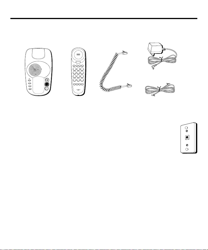
PARTS CHECKLIST ...................................... 6
MODULAR JACK REQUIREMENTS .................. 6
INSTALLATION ................................................ 7
INSTALLING AND REPLACING THE BATTERY ...... 7
IMPORTANT INSTALLATION INFORMATION ........
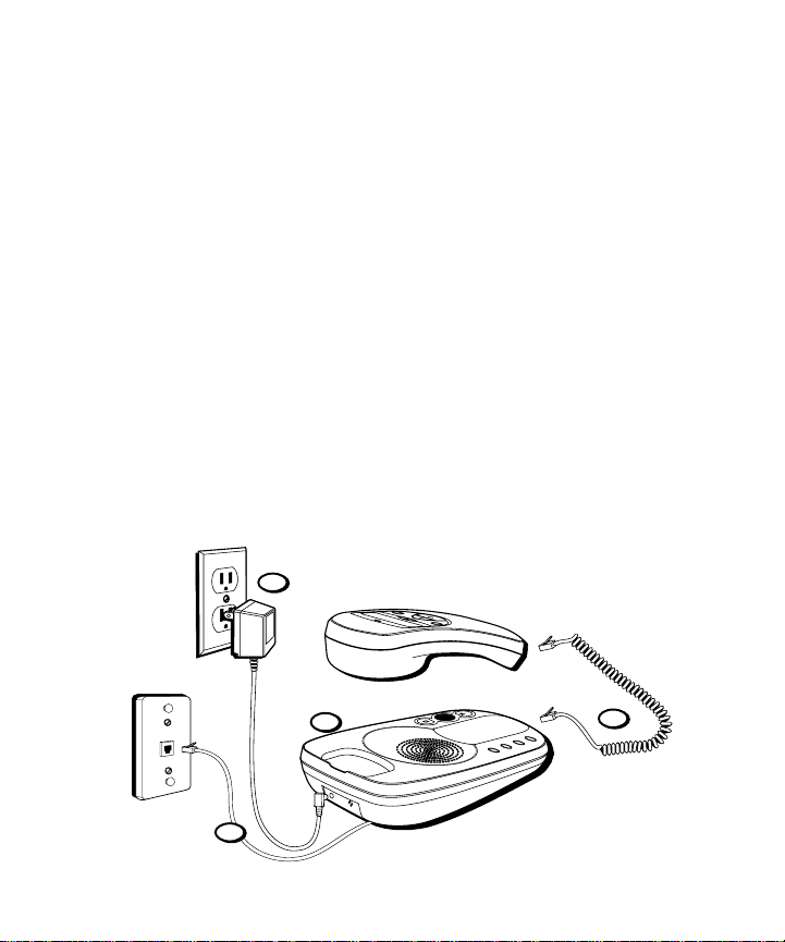
DESKTOP INSTALLATION .............................. 9
WALL MOUNT INSTALLATION ..................... 10
IMPORTANT INSTRUCTIONS FOR MOVING
THE UNIT ....................................11
TELEPHONE BASICS ...................................... 12
SETTING UP THE CALLER ID MENU ............ 12
SETTING Y OUR LOCAL AREA CODE ........ 13
SETTING THE REGIONAL AREA CODE ...... 14
SETTING THE CID DISPLAY LANGUAGE .... 15
SETTING THE LCD CONTRAST .............. 15
SETTING THE DIAL MODE .................... 16
EXITING SETUP .................................. 16
ADJUSTING THE HANDSET V OLUME ............. 17
REDIALING A NUMBER .............................. 17
ONE T OUCH REDIAL ................................. 17
FLASH ................................................... 17
TEMPORARY T ONE DIALING ....................... 1
ANSWERING MACHINE SET UP...................... 19
RECORDING THE GREETING ........................ 19
CHANGING THE ANSWERING SYSTEM
SETTINGS ................................... 20
SETTING THE T IME/DAY ............................. 20
DAY ................................................. 20
HOUR .............................................. 21
MINUTES .......................................... 21
SETTING THE RINGS TO ANSWER ................ 22
TOLL SAVER ........................................... 22
INCOMING MESSAGE LENGTH .................... 22
SETTING THE SECURITY CODE .................... 23
ANSWERING SYSTEM OPERATION ................... 24
ADJUSTING THE V OLUME ........................... 24
ANSWERING SYSTEM ON/OFF INDICATOR .... 24
MESSAGES INDICATOR .............................. 24
PLAYING MESSAGES ................................ 25
ERASING A MESSAGE ............................... 25
ERASING ALL MESSAGES .......................... 25
LEAVING A MEMO ................................... 25
SCREENING CALLS (AUTO DISCONNECT
FEATURE) ............................................... 26
REMOTE ACCESS ..................................... 26
ACCESSING Y OUR ANSWERING SYSTEM ....... 26
CALLER ID FEATURES ................................... 27
SUMMARY SCREEN .................................. 27
RECEIVING AND STORING CALLS ................. 27
REVIEWING CALL RECORDS ....................... 2
DELETING CALL RECORDS ......................... 2
DIALING BACK ........................................ 2
IF YOU PROGRAMMED YOUR LOCAL
AREA CODE IN THE SETUP MENU ...... 2
IF YOU DID NOT PROGRAM YOUR LOCAL
AREA CODE IN THE SETUP MENU ...... 29
CALLER ID MESSAGES ................................. 30

4
MEMORY .................................................... 30
STORING EMERGENCY/QUICK DIAL
NUMBERS IN MEMORY LOCATIONS ............. 31
STORING FREQUENTLY CALLED
NUMBERS IN MEMORY LOCATIONS ..... 31
CHANGING A STORED NUMBER .................. 32
TRANSFER A CALLER ID RECORD TO
A MEMORY LOCATION ...................... 32
ERASING A NUMBER STORED IN A
MEMORY LOCATION .......................... 32
DIALING A QUICK DIAL NUMBER
STORED IN A MEMORY LOCATION ........ 33
DIALING A FREQUENTLY CALLED
NUMBER STORED IN A MEMORY LOCATION ... 33
REVIEWING A NUMBER STORED IN
A MEMORY LOCATION ......................... 33
PAUSE (REDIAL) ...................................... 33
TROUBLESHOOTING T IPS ................................ 35
GENERAL PRODUCT CARE ............................. 38
SERVICE ..................................................... 38
INDEX ........................................................ 39
REMOTE ACCESS CARD ................................. 41
LIMITED W ARRANTY ..................................... 42

5
INTRODUCTION
Your Caller ID Phone with Digital Answering System is designed to give
you flexibility in use and high quality performance. To get the most from
your new Caller ID Phone with Digital Answering System, we suggest that
you take a few minutes right now to read through this instruction manual.
Your Caller ID phone stores and displays specific information, provided by
your local telephone company, to subscribers of Caller ID or similar caller
identification services. You must subscribe to one of these services in order
to use this unit.
Your Caller ID phone enables you to:
• Identify callers before you answer the phone.
• View the time and date of each incoming call.
• Record up to 75 Caller ID messages sequentially.
• Know who called while you were away.
IMPORTANT: In order to use all of the features of this unit, you must
subscribe to the standard Name/Number Caller ID Service.
CAUTION: When using telephone equipment, there are basic safety
instructions that should always be followed. Refer to the IMPORTANT
SAFETY INSTRUCTIONS provided with this product and save them for
future reference.

6
BEFORE YOU BEGIN
PARTS CHECKLIST
Make sure your package includes the following items:
MODULAR JACK REQUIREMENTS
To properly connect your phone to your telephone lines, you
should identify the type of wall jack(s) you have. You will need an
RJ11-type single line modular phone jack, which is the most
common type of phone jack and might look like the one pictured
here. If you don’t have a modular jack, or you are unable to
identify your modular jack, call your local phone company to find
out how to get one installed.
Base Coiled handset
cord
Telephone line cord
Handset
AC power supply
set
answerer on/off
greeting
memo
erase
p
r
e
v
i
o
u
s
play
next
s
t
o
p
/
s
e
t
AB
*
0
#
OPER
78
123
456
9
ABC DEF
JKLGHI MNO
TUV
PQRS
WXYZ
Memory Flash
Redial
Volum e
C
Store Quick Dial

7
INSTALLATION
INSTALLING AND REPLACING THE BATTERY
Your Caller ID telephone with answering system uses one 9-volt alkaline
battery (not included) for backup power. In the event of a power outage,
you are still be able to use this phone to make and receive calls and
answering system messages and Caller ID information stored in memory
is retained.
CAUTION: Always disconnect phone cords from the wall outlets before
battery installation or replacement.
To install the battery:
1. Carefully turn over the phone. Remove the battery compartment door
on the bottom of the unit by loosening the screw with a Phillips
screwdriver. Lift the door.
2. Connect a fresh or replace the old 9-volt alkaline battery (not included). The
large and small contacts on the battery clip and the battery will interlock.
Once connected, place the battery inside the battery compartment.
3. Replace the battery compartment door and tighten the screw.
LINE
Battery clip
Battery
compartment
Battery

8
NOTE: If the low battery icon (
LOW
) appears in the display, you need to
replace the battery. It is important that you replace the battery as soon as
possible to retain answering system messages and phone memory and to
maintain Caller ID operation during a power outage.
During battery replacement, a backup circuit in the unit will retain your stored
Caller ID information for up to 90 seconds. Write down any stored Caller ID
information you do not want erased.
NOTE: If the battery is low or not installed, the unit announces “Low Battery” at
the end of your messages. Remove battery when storing this unit over one month.
IMPORTANT INSTALLATION INFORMATION
• Always disconnect phone cords from the wall outlets before battery
installation or replacement.
• Never install telephone wiring during a lightning storm.
• Never touch uninsulated telephone wires or terminals, unless the
telephone line has been disconnected at the network interface.
• Never install telephone jacks in wet locations unless the jack is
specifically designed for wet locations.
• Use caution when installing or modifying telephone lines.
• To reduce the risk of fire, use only 9V alkaline battery.
IMPORTANT: You will have approximately 90 seconds to replace the batteries
before the stored caller ID information in the handset memory are lost. Please
read the instructions before replacing the battery and have the battery ready
to be inserted beforehand.
NOTE: If the 9V alkaline battery is not installed, you will still be able to make
and receive calls with your phone during a power loss.

9
DESKTOP INSTALLATION
1. Plug the coiled cord into the handset. Plug the other end into the jack on
the lower end of the base. Place the handset in the cradle on the base.
2. Plug the line cord into the jack on the bottom of the base. Plug the other
end into a wall jack.
3. Plug the two-prong end of the AC power supply into an AC electrical
outlet and the other end into the POWER 9V DC jack on the back of the
unit. The unit announces, "Please wait" and plays a long beep, and then
three short beeps when unit is ready for setup or to answer calls with
the default greeting and settings.
4. Set the RINGER switch on the side of the base to the desired loudness:
• HI = Loudest sound.
• LO = Sound will be lower.
• OFF = Telephone will not ring.
5. The unit is properly installed if you pick up the handset and hear the dial
tone. Otherwise, recheck all installation steps.
1
2
3
4

10
WALL MOUNT INSTALLATION
The Caller ID phone with digital answering system can be mounted on a
wall phone plate (not included).
1. Plug the phone cord into the phone jack on the bottom of the unit, and
wrap the extra phone line around the bottom of the base. Feed the line
cord through the grooves so that the base area is flat for wall mounting.
2. Plug the two-prong end of the AC power supply into an AC outlet and
the other end into the POWER 9V DC jack on the back of the unit. The
unit announces, "Please wait" and plays a long beep, and then three short
beeps when unit is ready for setup or to answer calls with the default
greeting and settings.
3. Connect the other end of the phone line to the modular jack on the wall.
4. Place the handset in the cradle of the base as soon as possible to hang
up the phone.
CAUTION: Only use the ATLINKS USA, Inc. 5-2498 power supply that was
packed with this unit. Using other power supplies may damage the unit.
set
answerer on/off
greeting
memo
erase
r
e
v
i
e
w
play
skip
s
t
o
p
/
s
e
t
new
options
dialdelete
r
e
v
i
e
w
1
4
5
3
7
2
6

11
5. Plug one end of the coiled cord into the handset and the other end into
the jack on the lower end of the base.
6. Slip the mounting holes over the wall plate posts and firmly slide the
unit down into place.
7. Set the RINGER VOLUME switch as desired.
• HI = Loudest sound
• LO = Sound will be lower.
• OFF = Telephone will not ring
. The unit is properly installed if you pick up the handset and hear the dial
tone. Otherwise, recheck all installation steps.
IMPORTANT INSTRUCTIONS FOR MOVING THE UNIT
To move the unit to a different location in the house, follow these instructions:
1. Disconnect the phone line.
2. Install a battery, if you have not already done so. This ensures that your
messages are not lost. Refer to “Installing and Replacing the Battery” on
page 7.
3. Unplug the power supply from the electrical outlet.
4. Move the unit and phone line to the desired location.
5. Plug the power supply into an electrical outlet and to the back of the phone.
6. Connect the phone line at the new location.

12
TELEPHONE BASICS
SETTING UPTHE CALLER ID MENU
You should not plug the telephone into the wall line jack while setting up
the Caller ID menu. An incoming call may invalidate the information if it
was not yet saved.
1. With the handset in the cradle, press the options button and release,
“SET OR ” appears on the display. The unit enters the setup menu.
AB
*
0
#
OPER
78
123
456
9
ABC DEF
JKLGHI MNO
TUV
PQRS
WXYZ
Memory Flash
Redial
Volu me
C
Store Quick Dial
Flash
button
Redial
button
Store
button
Memory
button
Memory
buttons
Volume
button
new
options
dialdelete
r
e
v
i
e
w
delete
button dial
button
options
button
new call indicator
review
buttons

13
2. Press either review up or down button to scroll among the seven menu
screens, which are:
• SET OR
• LOCAL AREA CODE (default - - -)
• REGIONAL AC’S (all default - - -)
• SELECT LANGUAGE (default English)
• SELECT CONTRAST (default 3)
• T/P DIAL MODE (default tone)
• EXIT SETUP
NOTE: You have ten seconds following any key press before the phone
automatically returns to the CALLS summary screen.
SETTING YOUR LOCAL AREA CODE
The telephone uses the programmed area code to determine the number
format to display when a valid Caller ID signal is received. The
programmed area code is also used for the dialback feature.
1. After the unit enters the setup menu, press the review up button until
LOCAL AREA CODE
appears.
2. To enter or change the area code, press the options button. The display
shows the stored area code. The left-most digit or a minus sign (-)
flashes, indicating the unit is ready to accept the area code entry.
3. Press review down to choose 9-0 for the first digit.
4. When the desired digit is flashing, press review up to advance to the
next digit.

14
5. Repeat steps 3 and 4 until all the digits for your area code are correct.
NOTE: If you make a mistake, you can simply retrace the previous steps until
your area code is set or press the delete button to delete the current local area
code and start over.
6. Press options to store the area code and return to the
LOCAL AREA
CODE
display.
SETTING THE REGIONAL AREA CODE
You may enter multiple Local/Regional Area Codes (L/RAC) to assist in 10
digit call determination for the dial back feature. This feature is useful in
regions with multiple L/RAC’s which require 10 digit dialing between them.
1. After the unit enters the setup menu, press the review up button until
REGIONAL AC’S
appears.
2. To enter or change the stored area code, press the options button. The
display shows the stored regional area code. The left-most digit, or a
minus sign(-), flashes, indicating the unit is ready to accept the regional
area code entry.
3. Press review down to choose 9-0 for the first digit.
4. When the desired digit is flashing, press review up to advance to the
next digit.
5. Repeat steps 3 and 4 unit all the digits for the regional area code are
correct.
NOTE: If you make a mistake, you can simply retrace the previous steps until
the correct regional code is set, or press delete to delete the current regional
area code and start over. You may enter up to six sets of regional area codes.

15
6. Press options to store the regional area code and return to the
REGIONAL AC’S display.
7. To exit
REGIONAL AC’S
menu, press dial.
SETTING THE CID DISPLAY LANGUAGE
This adjustment allows the Caller ID messages to be displayed in English,
French or Spanish.
1. After the unit enters the setup menu, press the review up button until
SELECT LANGUAGE
appears.
2. Press the options button to show the current language setting. The
default is English.
3. Press review up or down to change the language.
4. Press options to store the language selection and return to the
SELECT
LANGUAGE
display.
SETTING THE LCD CONTRAST
This adjustment allows you to adjust the contrast and viewing angle of
the display.
1. After the unit enters the setup menu, press the review up button until
SELECT CONTRAST
appears.
2. Press the options button to show the current contrast setting. There are
five levels of contrast, with the default set to 3.
3. To decrease the contrast, press review down. To increase, press
review up.

16
4. Press options to store the contrast setting and return to the
SELECT
CONTRAST
display.
SETTING THE DIAL MODE
This adjustment allows you to select tone (touch-tone) or pulse (rotary) dialing.
1. After the unit enters the setup menu, press the review up button until
T/P DIAL MODE
appears.
2. Press the options button to show the current dial mode. The default is
set to tone.
3. To change the dial mode, press review up or down. The display
alternates between the two modes.
4. Press options to store the dial mode and return to the
T/P DIAL
MODE
display.
EXITING SETUP
To exit the setup mode after your changes are made, select the
EXIT
SETUP
menu and press the options button. Alternatively, to exit the setup
menu, press the dial button.
NOTE: The phone exits setup after 10 seconds if no buttons are pressed.
IMPORTANT: The time and date are programmed automatically when the
first Caller ID information is successfully received after setup.

17
ADJUSTING THE HANDSET VOLUME
You may control the listening level with the Volume button, which has
four levels.It remains at the last level you selected until you change it.
REDIALING ANUMBER
If you want to call the last number you dialed (up to 32 digits), use
Redial.
1. Pick up the handset.
2. Press Redial. The last number called is automatically redialed.
ONE TOUCH REDIAL
If the last number you dialed is busy, you can redial it immediately,
without hanging up the handset, by pressing the Redial button.
FLASH
Use Flash to activate special features of your telephone network, such as
call transfer, or special services from your local telephone company, such
as call waiting. These services generally require an extra monthly fee. If
you subscribe to any of these services, please refer to the phone
company’s instructions on how to use Flash.
Answering an incoming call during a conversation:
• After you hear the Call Waiting tone, press and release the Flash button.
The first call is placed on hold while the second call can be answered.

18
Returning to our first call and placing the second call on hold:
• Press and release Flash again. The first call can continue while the
second call is put on hold.
TEMPORARY TONE DIALING
If you have pulse (rotary) service, and want to access customer calling
services that require tone dialing (such as telebanking and long
distance services) you can use this feature to temporarily change from
pulse to tone service.
After dialing the telephone number and connecting to the customer
calling service:
1. Press and release the *(TONE) button.
2. The phone remains in tone mode until you hang up. Then the phone
automatically returns to the pulse dialing mode.

19
ANSWERING MACHINE SET UP
RECORDING THE GREETING
Before using your new answering system, you should record a greeting
(the announcement callers hear when the answering system answers a
call). If you don't record a greeting, callers hear a default greeting which
says, "After tone, record message."
When recording the greeting you should be about six inches from the unit.
Eliminate as much background noise as possible.
1. Prepare your greeting.
Sample Greeting: Hi, this is (use your name here). I can’t answer the phone right
now, so please leave your name, number, and a brief message after the tone, and I’ll get
back to you. Thanks.
set
answerer on/off
greeting
memo
erase
p
r
e
v
i
o
u
s
play
next
s
t
o
p
/
s
e
t
greeting button
stop/set button
set
answerer on/off button
memo button
erase button
play/next button &
answering system/
messages indicator
previous button

20
2. Press and hold greeting button until the unit announces, "Record greeting
after tone." After the tone, you have 30 seconds to record your message.
3. Release the greeting button when finished. The recorded greeting plays
back automatically.
NOTE: Your recording time should not be less than 2 seconds. Otherwise the
unit uses the default greeting.
CHANGING THE ANSWERING SYSTEM SETTINGS
This function allows you to change the Time/Day, Rings to Answer, and
Security Code settings.
Default Settings
Time - Sunday 12:00 am
Security Code - 123
SETTING THE TIME/DAY
This process allows you to set the current day and time for the Time/Day
stamp attached to each message.
DAY
1. Press and hold the stop/set button until the unit announces,"Time (the
current day/time setting) To set day, press next...press time/set to continue."
NOTE: You have six seconds following any key press before the answering
system automatically exits the Time/Day setting mode.
2. To change the day, press and release the next or previous button until
the desired setting is announced.
3. Press the stop/set button again to confirm the setting and enter the
Hour menu.
Table of contents
Languages:
Other GE Cordless Telephone manuals