Table
ofContents
...........................................................................................................................................................................
Active Vent
28
.......................................................................................................................................
Circulation Pumpand Motor 30
Component LocatorViews
...........................................................................................................................................
10
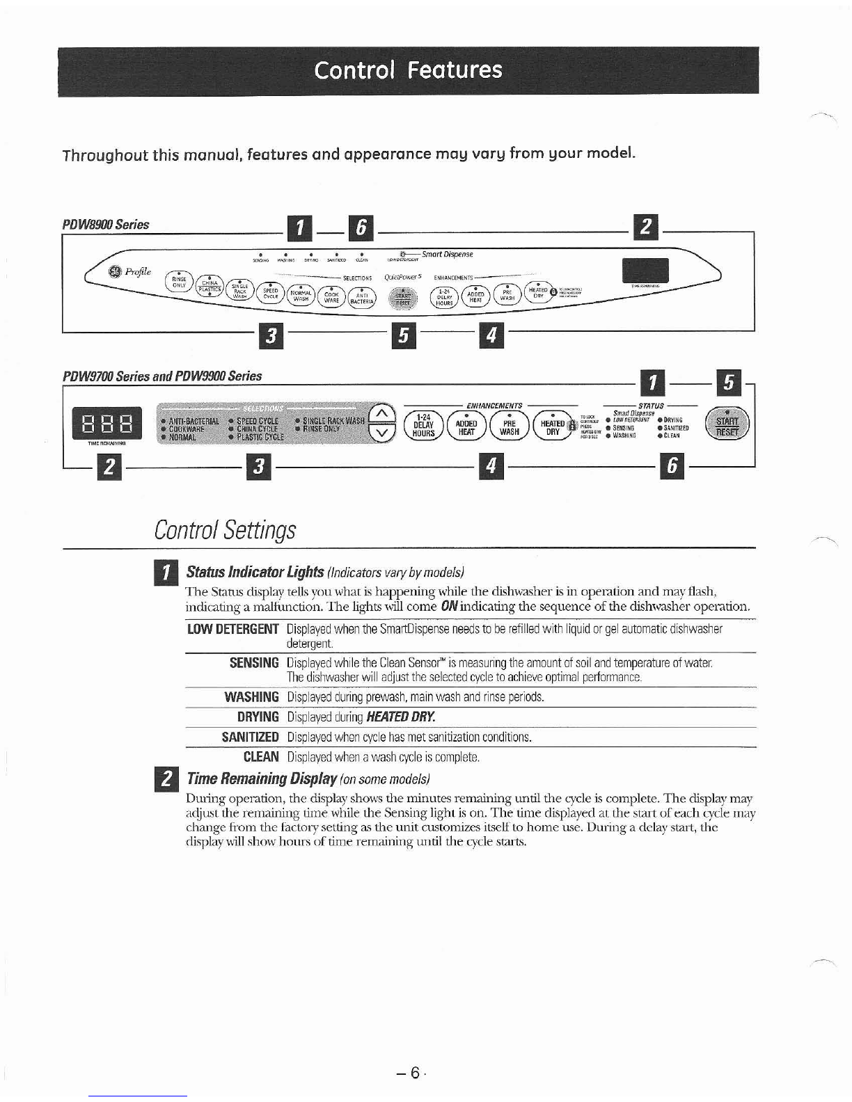
Control Features
................................................................................................................................................................
6
Control Module
..................................................................................................................................................................
27
..................................................................................................
Customer Purge ofthe Bulk DispenserTank
18
Demo Mode
......................................................................................................................................................................
26
DetergentfRinseModule
...............................................................................................................................................
19
DishwasherComponents
.........................................................................................................................................
12
Door Interlock Switch
......................................................................................................................................................
19
Door Panel
....................
...............
.........................................................................................................................................
12
Door Spring Installation
............................................................................................................................................
31
DrainSystem
......................................................................................................................................................................
24
Factory Test Mode
............................................................................................................................................................
33
Fan (PDW9700and PDW9900Series)
.....................................................................................................................
28
Fill Funnel
..............................................................................................................................................................................
21
Heating Element
................................................................................................................................................................
22
Introduction
.........................................................................................................................................................................
5
KeypadAssembly
.............................................................................................................................................................
13
Lower Spray Arm. Fine Filter.and InletCover
......................................................................................................
21
MainConduit
.......................................................................................................................................................................
21
MiddleSpray Arm
.............................................................................................................................................................
20
Nomenclature
....................................................................................................................................................................
4
...................................................................................................................................
SchematicsandStripCircuits
34
Service Mode
......................................................................................................................................................................
32
Single Rack WashTM
..........................................................................................................................................................
29
SmartDispenseTM
...............................................................................................................................................................
15
Smart FillSystem
..............................................................................................................................................................
24
.
.
Turb~d~tySensor
................................................................................................................................................................
23
Upper Spray Arm
..............................................................................................................................................................
21
..................................................................................
Usingthe Dishwasherwith the Upper Rack Removed 20
Warranty for 2005 Product
.........................................................................................................................................
36
....................................................................................................................
Warranty for 2006 and Later Product
37
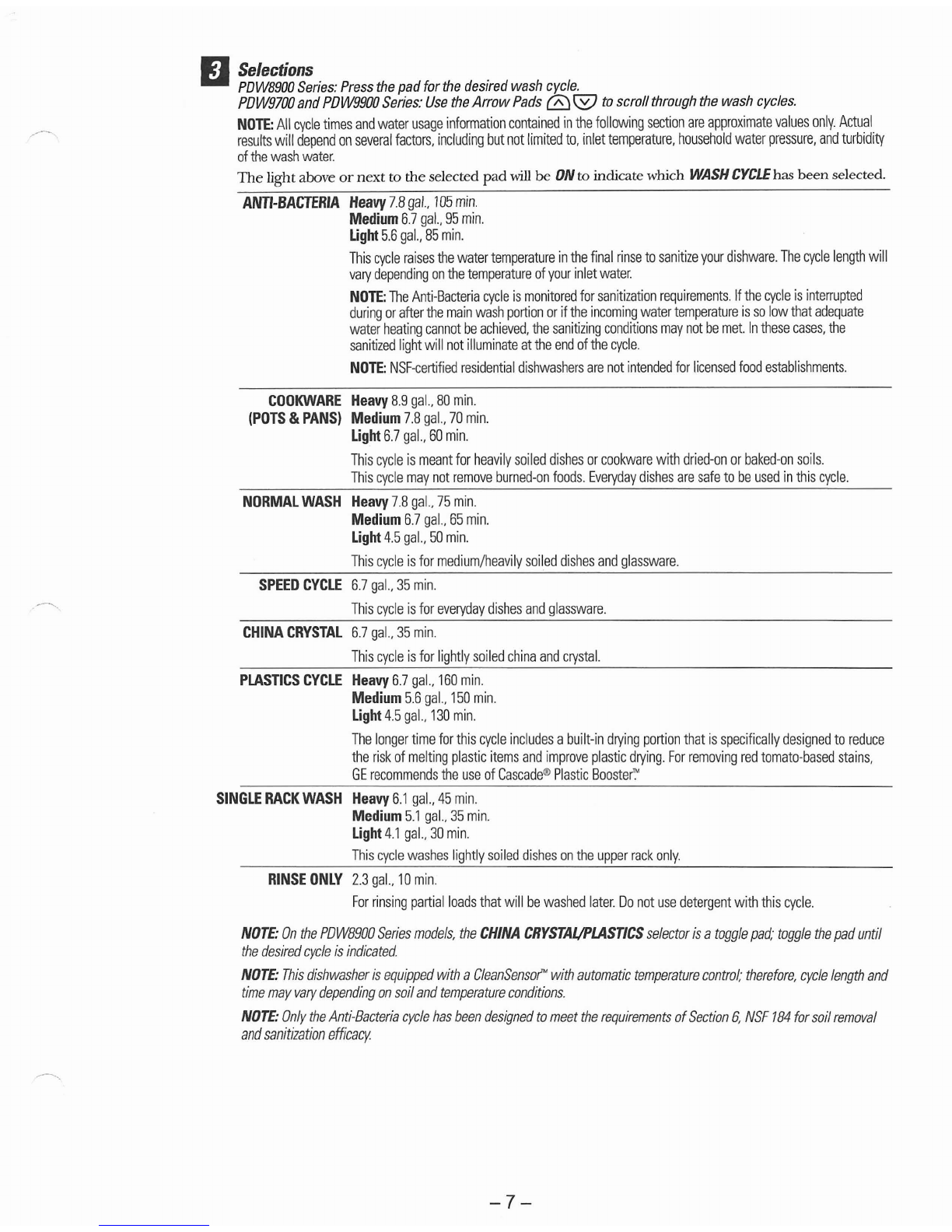
Wash Cycles
........................................................................................................................................................................
26
....................................................................................................................
Water HardnessTest and Calibration
14
Water Valve and FloodSwitch
....................................................................................................................................
25
Water Valve Test
...............................................................................................................................................................
25
................................................................................................................................................
Wax Motor and Magnet 30