GE GTDS850EDWS User manual

Installation
Instructions
Electric
Dryer
Questions on Installation? Call: 1-800-GECARES (US)
or Visit our Web site at: www.GEAppliances.com (US)
BEFORE YOU BEGIN
Read these instructions completely and carefully.
IMPORTANT - Save these instructions for local
inspector’s use.
IMPORTANT - Observe all governing codes and
ordinances.
Note to Installer - Be sure to leave these instructions with
the customer.
Note to Customer - Keep these instructions with your Use
and Care Book for future reference.
%HIRUHWKHROGGU\HULVUHPRYHGIURPVHUYLFHRUGLVFDUGHG
remove the dryer door.
6HUYLFHLQIRUPDWLRQDQGWKHZLULQJGLDJUDPDUHORFDWHGLQ
the control console.
'RQRWDOORZFKLOGUHQRQRULQWKHDSSOLDQFH&ORVH
supervision of children is necessary when the appliance is
used near children.
,QVWDOOWKHGU\HUZKHUHWKHWHPSHUDWXUHLVDERYH)IRU
satisfactory operation of the dryer control system.
7RUHGXFHWKHULVNRIVHYHUHLQMXU\RUGHDWK
follow all installation instructions.
&ORWKHVGU\HULQVWDOODWLRQPXVWEH
SHUIRUPHGE\DTXDOL¿HGLQVWDOOHU
,QVWDOOWKHFORWKHVGU\HUDFFRUGLQJWRWKHVHLQVWUXFWLRQVDQGLQ
accordance with local codes.
7KLVGU\HUPXVWEHH[KDXVWHGWRWKHRXWGRRUV
8VHRQO\ULJLGPHWDOµGLDPHWHUGXFWZRUNLQVLGHWKHGU\HU
cabinet and use only UL approved transition ducting between
the dryer and the home duct.
'2127LQVWDOODFORWKHVGU\HUZLWKÀH[LEOHSODVWLFYHQWLQJ
PDWHULDOV,IÀH[LEOHPHWDOVHPLULJLGRUIRLOW\SHGXFWLV
LQVWDOOHGLWPXVWEH8/OLVWHGDQGLQVWDOOHGLQDFFRUGDQFHZLWK
the instructions found in “Connecting Dryer to House Vent”
ODWHULQWKLVPDQXDO)OH[LEOHYHQWLQJPDWHULDOVDUHNQRZQWR
FROODSVHEHHDVLO\FUXVKHGDQGWUDSOLQW7KHVHFRQGLWLRQVZLOO
REVWUXFWFORWKHVGU\HUDLUÀRZDQGLQFUHDVHWKHULVNRI¿UH
'RQRWLQVWDOORUVWRUHWKLVDSSOLDQFHLQDQ\ORFDWLRQZKHUHLW
FRXOGEHH[SRVHGWRZDWHUDQGRUZHDWKHU
7RUHGXFHWKHULVNRIVHYHUHLQMXU\RUGHDWKIROORZDOO
installation instructions.
6DYHWKHVHLQVWUXFWLRQV,QVWDOOHUV%HVXUHWROHDYHWKHVH
instructions with the customer).
'35HY
NOTE: Installation and service of this dryer requires basic
mechanical and electrical skills. It is your responsibility to contact
DTXDOL¿HGLQVWDOOHUWRPDNHWKHHOHFWULFDOFRQQHFWLRQV
7KLVLVWKHVDIHW\DOHUWV\PERO7KLVV\PERODOHUWV\RXWR
potential hazards that can kill or hurt you and others.
All safety messages will follow the safety alert symbol and the word
´'$1*(5µ´:$51,1*µRU´&$87,21µ7KHVHZRUGVDUHGH¿QHGDV
Indicates a hazardous
VLWXDWLRQZKLFKLIQRW
DYRLGHGwill result in
GHDWKRUVHULRXVLQMXU\
Indicates a hazardous
VLWXDWLRQZKLFKLIQRW
DYRLGHGcould result in
GHDWKRUVHULRXVLQMXU\
Indicates a hazardous
VLWXDWLRQZKLFKLIQRW
DYRLGHGcould result in
PLQRURUPRGHUDWHLQMXU\
DANGER
CAUTION
WARNING
WARNING
Fire Hazard
1RZDVKHUFDQFRPSOHWHO\UHPRYHRLO
'2127GU\DQ\WKLQJWKDWKDVHYHUKDGDQ\
type of oil on it (including cooking oils).
,WHPVFRQWDLQLQJIRDPUXEEHURUSODVWLF
must be dried on a clothesline or by using
DQ$LU'U\F\FOH
)DLOXUHWRIROORZWKLVLQVWUXFWLRQVFDQUHVXOW
RQGHDWKRU¿UH
3OXJLQWRDJURXQGHGSURQJRXWOHW
'2127UHPRYHJURXQGSURQJ
'2127XVHDQDGDSWHU
'2127XVHDQH[WHQVLRQFRUG
)DLOXUHWRGRVRFDQUHVXOWLQGHDWK¿UHRU
electrical shock.
.HHSÀDPPDEOHPDWHULDOVDQGYDSRUVVXFK
DVJDVROLQHDZD\IURPGU\HU
3ODFHGU\HUDWOHDVWLQFKHVFPDERYH
WKHÀRRUIRUDJDUDJHLQVWDOODWLRQ
)DLOXUHWRGRVRFDQUHVXOWLQGHDWK
H[SORVLRQRU¿UH.
Fire Hazard
Electrical
Shock Hazard
Explosion
Hazard
WARNING
'2127DOORZFKLOGUHQRQRULQWKHDSSOLDQFH
Close supervision of children is necessary
when the appliance is used near children.

Installation Instructions
Minimum Clearance in Alcove or Closet Installation
0LQLPXPFOHDUDQFHWRFRPEXVWLEOHVXUIDFHVDQGIRUDLURSHQLQJDUHLQFOHDUDQFHERWKVLGHVLQIURQWLQWRSDQGLQUHDU
Consideration must be given to provide adequate clearance for installation and service
2
6WHS3UHSDUHWKHDUHDDQGH[KDXVWIRULQVWDOODWLRQRIQHZ
GU\HUVHHVHFWLRQ
6WHS &KHFNDQGHQVXUHWKHH[LVWLQJH[WHUQDOH[KDXVWLVFOHDQ
VHHVHFWLRQDQGPHHWVDWWDFKHGLQVWDOODWLRQ
VSHFL¿FDWLRQVVHHVHFWLRQ
6WHS 5HPRYHWKHIRDPVKLSSLQJSDGVVHHVHFWLRQ
6WHS 0RYHWKHGU\HUWRWKHGHVLUHGORFDWLRQ
6WHS &RQQHFWWKHSRZHUVXSSO\VHHVHFWLRQ
6WHS &RQQHFWWKHH[WHUQDOH[KDXVWVHHVHFWLRQ
6WHS /HYHO\RXUGU\HUVHHVHFWLRQ
6WHS &KHFNWKHRSHUDWLRQRIWKHSRZHUVXSSO\DQGYHQWLQJ
6WHS 3ODFHWKHRZQHUVPDQXDODQGWKHLQVWDOODWLRQLQVWUXFWLRQ
in a location where they will be noticed by the owner.
)RUDOFRYHRUFORVHWLQVWDOODWLRQVHHVHFWLRQ
)RUEDWKURRPRUEHGURRPLQVWDOODWLRQVHHVHFWLRQ
)RUPRELOHRUPDQXIDFWXUHGKRPHVHHVHFWLRQ
)RUJDUDJHLQVWDOODWLRQVHHVHFWLRQ
)RUVLGHRUERWWRPH[KDXVWVHHVHFWLRQ
)RUFRQQHFWLQJLQOHWKRVHVVHHVHFWLRQ
)RUGRRUUHYHUVLQJLQVWUXFWLRQVVHHVHFWLRQ
1
INTERNAL
DUCT
OPENING
CHECK THE EXHAUST
HOOD DAMPER OPENS
AND CLOSES FREELY
WALL
TILT THE DRYER
SIDEWAYS AND
REMOVE THE FOAM
SHIPPING PADS BY
PULLING AT THE SIDES
AND BREAKING THEM
AWAY FROM THE
DRYER LEGS.
BE SURE TO
REMOVE
ALL OF THE
FOAM PIECES
AROUND
THE LEGS.
PREPARING FOR INSTALLATION OF NEW
DRYER
TIP: ,QVWDOO\RXUGU\HUEHIRUHLQVWDOOLQJ\RXUZDVKHU7KLVZLOO
DOORZEHWWHUDFFHVVZKHQLQVWDOOLQJGU\HUH[KDXVW
REMOVING LINT FROM WALL EXHAUST OPENING
5HPRYHDQGGLVFDUGH[LVWLQJSODVWLFRUPHWDOIRLOWUDQVLWLRQGXFW
and replace with UL listed transition duct.
TOOLS YOU
WILL NEED
PHILLIPS SCREWDRIVER
SLIP JOINT PLIERS
LEVEL
FLAT BLADE SCREWDRIVER
MATERIALS YOU WILL NEED
GLOVES
SAFETY
GLASSES
DRYER POWER
CORD KIT
(NOT PROVIDED
WITH DRYER)
4" DUCT
CLAMPS (2)
OR
4" SPRING
CLAMPS (2)
EXHAUST
HOOD
3/4" STRAIN
RELIEF
UL RECOGNIZED
4" DIA. METAL
ELBOW
DIA. FLEXIBLE METAL (SEMI-RIGID)
UL LISTED TRANSITION DUCT
(IF NEEDED)
W
X08X10077 (INCLUDES 2 ELBOWS)
4" DIA. METAL DUCT
(RECOMMENDED)
"
DIA. FLEXIBLE METAL (FOIL TYPE)
UL LISTED TRANSITION DUCT
(IF NEEDED.)
UL-APPROVED
FOIL TAPE
UL RATED
120/240V,30A
WITH 3 OR 4 PRONGS.
IDENTIFY THE PLUG
TYPE AS PER THE
HOUSE RECEPTACLE
BEFORE PURCHASING
LINE CORD.
4” COVER PLATE (IF NEEDED
(KIT WE1M454)

Installation Instructions
3
2ELECTRICAL CONNECTION INFORMATION
TO REDUCE THE RISK OF FIRE,
ELECTRICAL SHOCK AND PERSONAL
INJURY:
'212786($1(;7(16,21&25'
OR AN ADAPTER PLUG WITH THIS
APPLIANCE.
'U\HUPXVWEHHOHFWULFDOO\JURXQGHGLQDFFRUGDQFHZLWKORFDO
FRGHVDQGRUGLQDQFHVRULQWKHDEVHQFHRIORFDOFRGHVLQ
accordance with the
1$7,21$/(/(&75,&$/&2'($16,1)3$
12RU&DQDGLDQ(OHFWULFDO&RGH&6$&
ELECTRICAL REQUIREMENTS:
7KLVGU\HUPXVWEHFRQQHFWHGWRDQLQGLYLGXDOEUDQFKFLUFXLW
protected by the required time-delay fuses or circuit breakers.
$IRXURUWKUHHZLUHVLQJOHSKDVH9RU9+]
DPSFLUFXLWLVUHTXLUHG,IWKHHOHFWULFVXSSO\GRHVQRWPHHW
WKHDERYHVSHFL¿FDWLRQVWKHQFDOODOLFHQVHGHOHFWULFLDQ
GROUNDING INSTRUCTIONS:
For a grounded, cord-connected dryer: 7KLVGU\HU
PXVWEHJURXQGHG,QWKHHYHQWRIDPDOIXQFWLRQRUEUHDNGRZQ
grounding will reduce the risk of electric shock by providing
DSDWKRIOHDVWUHVLVWDQFHIRUHOHFWULFFXUUHQW7KLVGU\HUXVHV
a cord having an equipment grounding conductor and a
JURXQGLQJSOXJ7KHSOXJPXVWEHSOXJJHGLQWRDQDSSURSULDWH
outlet that is properly installed and grounded in accordance
with all local codes and ordinances.
For a permanently connected dryer: 7KLVGU\HUPXVW
EHFRQQHFWHGWRDJURXQGHGPHWDOSHUPDQHQWZLULQJV\VWHP
or an equipment grounding conductor must be run with the
circuit conductors and connected to the equipment grounding
terminal on the appliance.
Improper connection of the equipment-grounding conductor
FDQUHVXOWLQDULVNRIHOHFWULFVKRFN&KHFNZLWKDTXDOL¿HG
electrician or service representative or personnel if you are
in doubt as to whether the appliance is properly grounded.
'2127PRGLI\WKHSOXJRQWKHSRZHUVXSSO\FRUG,ILWZLOO
QRW¿WWKHRXWOHWKDYHDSURSHURXWOHWLQVWDOOHGE\DTXDOL¿HG
electrician.
SAVE THESE INSTRUCTIONS
CONNECTING DRYER USING 4-WIRE
CONNECTION
(MUST BE USED FOR MOBILE HOME INSTALLATION)
NOTE: Since January 1,1996, the National Electric code requires that
the new constructions utilize a 4-wire connection to an electric dryer.
NEVER LEAVE THE
COVER OFF OF THE
TERMINAL BLOCK.
RELOCATE
GROUND SCREW
HERE
STRAIN
RELIEF
BRACKET
3/4", UL
RECOGNIZED
STRAIN RELIEF
SCREWS
NEUTRAL
(White)
HOT
WIRE
(3)
COVER
GREEN
OR YELLOW
WIRE
HOT
WIRE
Only a 4-conductor cord shall be used when the appliance is
installed in a location where grounding through the neutral
conductor is prohibited. Grounding through the neutral is
prohibited for the new branch-circuit installations, mobile
homes, recreational
vehicles, and areas where
local codes prohibit
grounding through the
neutral conduction.
1. Turn off the circuit breaker (s) (30 amp) or remove the dryer’s circuit fuse
at the electrical box.
2. Be sure the dryer cord is unplugged from the wall receptacle.
3. Remove the power cord cover located at the lower back
4. Remove and discard ground strap. Keep the green ground screw for step 7.
5. Install 3/4 in. UL recognized strain relief to power cord entry hole. Bring
power cord through strain relief.
6. Connect power cord as follows:
A. Connect the 2 hot lines to the outer screws of the terminal block (marked
L1 and L2).
B. Connect the neutral (white) line to the center of the terminal block
(marked N).
7. Attach ground wire of power cord with the green ground screw (hole
above strain relief bracket). Tighten all terminal block screws (3) completely.
8. Properly secure power cord to strain relief.
9. Replace the terminal block cover
10. Failure to do so can result on death, fire, or electrical shock.
· Use a new UL listed 240V 30 amp dryer power supply cord with closed
ring terminals or spade terminals with upturned ends.
· Use a UL listed strain relief.
· Disconnect power before making electrical connections.
· Securely tighten all electrical connections.
Electrical
Shock Hazard
Fire Hazard
WARNING
WARNING
WARNING
WARNING

Installation Instructions
CONNECTING DRYER USING 3-WIRE
CONNECTION
2. Be sure the dryer cord is unplugged from the wall.
3. Remove the power cord cover located at the lower back.
4. Install 3/4 in. UL recognized strain relief to power cord entry hole.
Bring power cord through strain relief.
5. Connect power cord as follows:
A. Connect the 2 hot lines to the outer screws of the terminal block
(marked L1 and L2).
B. Connect the neutral (white) line to the center of the terminal block
(marked N).
6. Be sure ground strap is connected to neutral (center) terminal of
block and to green ground screw on cabinet rear. Tighten all
terminal block screws (3) completely.
7. Properly secure power cord to strain relief.
8. Replace the terminal cover.
GREEN GROUND SCREW
STRAIN
RELIEF
BRACKET
3/4", UL
RECOGNIZED
STRAIN RELIEF
SCREWS (3)
GROUND STRAP
HOT
WIRE
COVER
NEUTRAL (White)
HOT
WIRE
3-wire Connection
Not for use in Canada.
DO NOT use for Mobile Home Installations.
NOT for use on new construction.
NOT for use on recreational vehicles.
NOT for use in areas where local codes
prohibit grounding through the neutral
conduction.
9. Failure to do so can result in death, fire, or electrical shock
1. Turn off the circuit breaker (s) (30 amp) or remove the dryer’s circuit
fuse at the electrical box.
· Use a new UL listed 240V 30 amp dryer power
supply cord with closed ring terminals or spade
terminals with upturned ends.
· Use a UL listed strain relief.
· Disconnect power
before making electrical
connections.
· Securely tighten all
electrical connections.
NEVER LEAVE THE
COVER OFF OF THE
TERMINAL BLOCK.
3EXHAUST INFORMATION
IN CANADA AND IN
THE UNITED STATES,
THE REQUIRED EXHAUST DUCT DIAMETER IS 4 in (102mm).
DO NOT USE DUCT LONGER THAN SPECIFIED IN THE EXHAUST
LENGTH TABLE.
;0&3($4(5+('3:,0*5,/(4$0'5+((0(3*:&145.
;('6&(5+('3:(3.,)(.
The correct exhaust installation is YOUR RESPONSIBILITY
Problems due to incorrect installation are not covered by
the warranty.
(/17($0'',4&$3'(9,45,0*2.$45,&13/(5$.)1,.53$04,5,10'6&5
$0'3(2.$&(8,5+!.,45('53$04,5,10'6&5
+(MAXIMUM ALLOWABLE'6&5.(0*5+$0'06/%(31)%(0'41)
5+((9+$6454:45(/'(2(0'462105+(5:2(1)'6&506/%(31)56304
5+(5:2(1)(9+$645+11'8$..&$2$0'$..&10',5,104015('%(.18
+(/$9,/6/'6&5.(0*5+)133,*,'/(5$.'6&5,44+180,05+e
5$%.(%(.18
· +('6&54+$..015%($44(/%.('8,5+4&3(841315+(3
)$45(0,0*/($045+$5(95(0',0515+('6&5$0'&$5&+.,05.
· 134,'(13%151/7(05,0*64(5+(&17(3-,5"51
&17(33($3(9+$64512(0,0*
EXHAUST LENGTH
.
.
.
#!
Exhaust Hood Types
(&1//(0'('
11)º
.% 18s,*,'
(5$. ,*,'
(5$.
((5
((5
((5
((5
2
!4(10.:)134+1 35
360,045$..$5,104
((5
((5
((5
((5
((5
((5
((5
((5
NORMAL
VENT
LONG
VENT
EXHAUST LENGTH
#!
Exhaust Hood Types
(&1//(0'('
11)º
.% 18s,*,'
(5$. ,*,'
(5$.
((5
((5
((5
((5
2
!4(10.:)134+1 35
360,045$..$5,104
((5
((5
((5
((5
((5
((5
WARNING
Fire Hazard
WARNING
WARNING

Installation Instructions
SEALING OF JOINTS
<
All joints should be tight to avoid leaks. The male end of each
section of duct must point away from the dryer.
<
The duct shall not be assembled with screws or other
fastening means that extend into the duct and catch lint.
<
Duct joints can be made air and moisture-tight by wrapping
the overlapped joints with duct tape.
<
Horizontal runs should slope down toward the outdoors
1/4 inch per foot.
INSULATION
Duct work that runs through an unheated area or is near air
conditioning should be insulated to reduce condensation and
lint build-up.
EXHAUST SYSTEM CHECK LIST
HOOD OR WALL CAP
<Terminate in a manner to prevent back drafts or entry of birds
or other wildlife.
<Termination should present minimal resistance to the exhaust
air flow and should require little or no maintenace to prevent clogging
<Never install a screen in or over the exhaust duct. This could
cause lint build up.
<Wall caps must be installed at least 12 in. above ground level
or any other obstruction with the opening pointed down.
SEPARATION OF TURNS
For best performance, separate all turns by at least 4 ft. of straight
duct, including distance between last turn and exhaust hood.
TURNS OTHER THAN 90º
<One turn of 45º or less may be ignored.
<Two 45º turns should be treated as one 90º turn.
<Each turn over 45º should be treated as one 90º turn.
PARTS AVAILABLE FROM LOCAL SERVICE
ORGANIZATIONS
<Rigid Metal Duct Components
WX8X63 4ʺx 1ʹDuct
WX8X64 4ʺx 2ʹDuct
WX8X51 4ʺElbow
WX8X59 4ʺAluminum Hood
<Flexible Metal Duct Components
WX8X58 4ʺClamps (2)
WX8X59 4ʺAluminum Hood
WX08X10077 6ʹUL-Listed, Flexible Metal (Semi-Rigid)
Duct, 2 Clamps, 2 Close Elbows
WE1M454 Cover rear exhaust opening
For every extra 90°elbow, reduce the allowable vent system
length by 10 ft.
Two 45° elbows will be treated like one 90° elbow.
For the side exhaust installations, add one 90° elbow to the
chart.
The total vent system length includes all the straight portions
and elbows of the system (transition duct included).
4EXHAUST CONNECTION
There are multiple installation options.
Select the most appropriate method for your
installation situation.
TO REDUCE THE RISK OF FIRE OR
PERSONAL INJURY:
+# $#")"%#$(%#$$ $ %$ "#
+# ),"$ "#$")"$"#$ %$$
$$")"$ $ (%#$$%#$#$
"'$$#$"%$ # %“Connecting the
Dryer to House Vent” ! $#%
+(%#$$ )$(%#$#&$
'$$"'#! " #! %
$%%$$ %"$! $$"*"
+%#!#$&$
+%#$ &$
+ " &$
+&"$"$$(%#$$ %$'$
$(%#$#)#$ $ "#$
%"$! $$"*"
+ $%#%$ "$#!$(%#$$
$ "%$#%%$$"$! $$
"*"
+&"#$#" " &"$(%#$%$#'
%#$$ %%$"$! $$"*"
+ $##%$' "'$)#$"#$$($$
$%$##$"#%%$$"$
! $$"*"
+ $ #$"%$ "(%#$"
+" &## "#!$ $(%#$
#)#$#!)$$%"# $#(%#$#)#$#
#!$$#$ )"
+%"$ '$##$"%$ #"#%$$ ""
Fire Hazard WARNING

Installation Instructions
CONNECTING THE DRYER TO HOUSE VENT
RIGID METAL TRANSITION DUCT
802$'34&27+/)perf02.#/%' #2+)+&.'4#-42#/3+4+0/
&5%4+3recommended.
8+)+&.'4#-42#/3+4+0/&5%43re&5%'4*'2+3,0(%253*+/)
#/&,+/,+/)
UL-LISTED FLEXIBLE METAL (SEMI-RIGID) TRANSITION DUCT
.'4#-3'.+2+)+&&5%4+/)%#/$'53'&+4WX08X10077).
04*'2'/%-03'&31#%'3
(''4.
T
!T
02342#+)*4-+/'+/34#--#4+0/%0//'%4
4*'&27'2'6*#534404*''64'2/#-
'6*#534*00&53+/)&5%44#1'02
clamp.
NOTE: WE STRONGLY RECOMMEND SOLID
METAL EXHAUST DUCTING. HOWEVER, IF
FLEXIBLE DUCTING IS USED IT MUST BE
UL-LISTED METAL, NOT PLASTIC.
STANDARD REAR EXHAUST
NOTE: ELBOWS WILL PREVENT DUCT
KINKING AND COLLAPSING.
Y
Y
D
RECOMMENDE
CONFIGURATION
TO MINIMIZE
EXHAUST
BLOCKAGE.
6*,()3++'$.$*)-$)-.''$)" '*1-.*.#.# ,3 ,
).# 1''$-#$"#'3re*(( ) - $''/-.,.$*)-
'*1'*1-''*1.# ,3 ,.*-$.'*- .*.# 1''
1$.#*/.&$)&$)")*,,/-#$)".# .,)-$.$*)duct
(2$($4$)",3$)"+ rformance.
60*$re-.$)".# /.*)-#,+*% .-.
UL-LISTED FLEXIBLE METAL (FOIL-TYPE) TRANSITION DUCT
6)-+ $'$)-.''.$*)-$.(3 ) --,3.**)) .
( .'- ($,$"$/.$)"))*. /- 1# , 7
$( . ,) ($).$) thr*/"#*/..# entire' )".#
*!.# .,)-$.$*)/..
!*$'.3+ /.-.#.*(+'31$.#.# 5/.'$) !*,'*.# -
,3 ,,)-$.$*)/./% .7-#'' /- .
*.# , )'*- -+ -
(
60*$re-.$)".# /.*)-#,+*% .-.
DO
ELBOW
REQUIRED
DON’T
DO NOT USE
EXCESSIVE
EXHAUST
LENGTH
DO NOT
CRUSH
FLEXIBLE
EXHAUST
AGAINST
WALL
DO NOT
SIT DRYER
ON FLEXIBLE
EXHAUST
ELBOWS
REQUIRED

Installation Instructions
4 LEVELING LEGS
LEVELING AND STABILIZING YOUR DRYER
the 4 leveling legs, at the corners, to ensure that the dryer
is level from side to side and front to rear.
5
LEVEL
SIDE-TO-SIDE
OPEN
DOOR 90
O
LEVEL
FRONT-TO-BACK
4 LEVELING LEGS
6ALCOVE OR CLOSET INSTALLATION
>If your dryer is approved for installation in an alcove or closet, it will
be stated on a label on the dryer back.
>The dryer MUST be vented to the outdoors. See the EXHAUST
INFORMATION sections 3 & 4.
>Minimum clearance between dryer cabinet and adjacent walls or
other surfaces is:
0 in. either side 52 in. from floor to overhead cabinets.
3 in. front
3 in. rear
>
ceiling, etc. is 52 in.
>
Closet ventilation openings required: 2 louvers each 60 square in.
(387 square cm), located 3 inches (7.6 cm) from top and bottom
of door. If the closet contains both a washer and a dryer, doors
must contain a minimum of 120 sq. in. of open area equally
distributed.
Before the “Alcove or Closet
installation”.
>Keep flammable materials and vapors,
such as gasoline, away from dryer.
>Failure to do so can result in death,
explosion, or fire.
Explosion Hazard
>Consideration must be given to provide adequate clearance for
installation and service
WARNING

Installation Instructions
10 DRYER EXHAUST TO RIGHT, LEFT OR
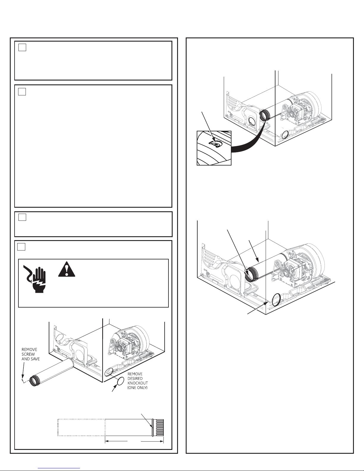
BOTTOM CABINET
Detach and remove the bottom, right or left side knockout
as desired. Remove the screw inside the dryer exhaust duct
and save. Pull the duct out of the dryer.
Cut the duct
as shown and keep portion A. 14"
AB
FIXING HOLE
7BATHROOM OR BEDROOM INSTALLATION
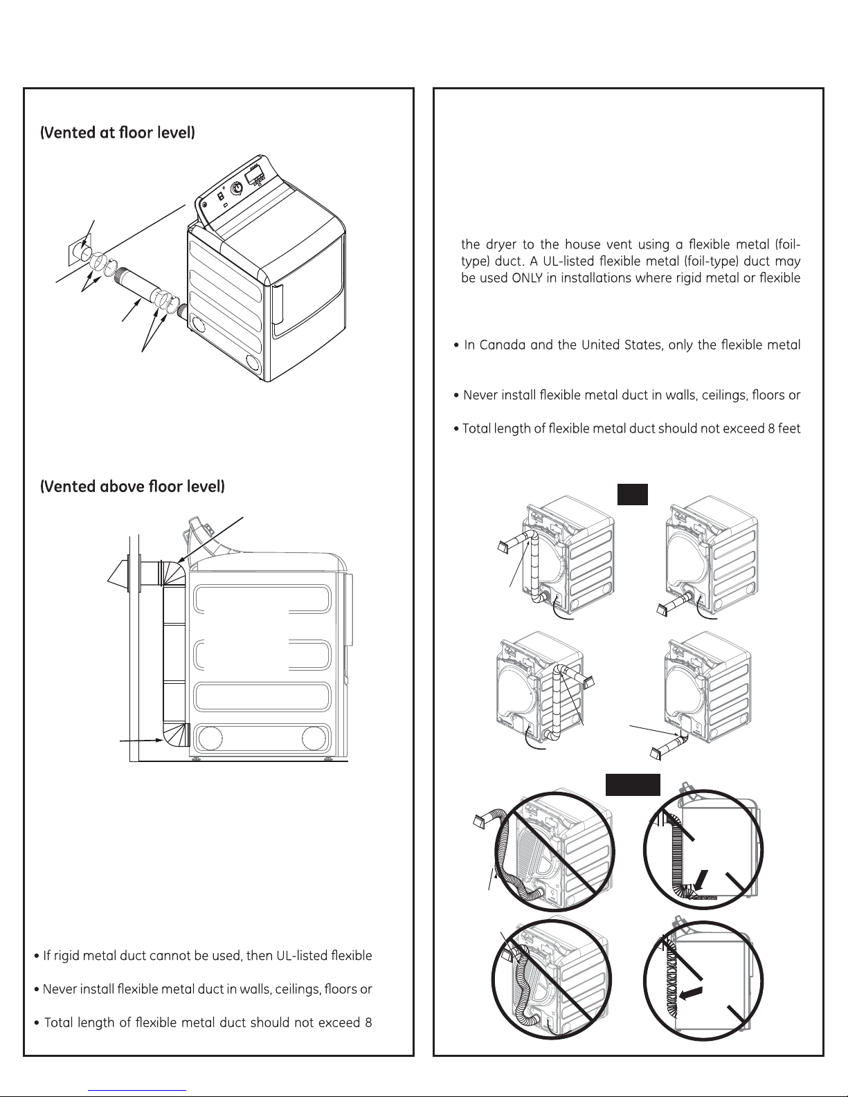
?The dryer MUST be vented to the outdoors. See EXHAUST
INFORMATION section 3 & 4.
?$/,0489(22(90543:89*54-573<09/25*(2*5+,857049/,()8,4*,
5-25*(2*5+,8<09/9/,$ $" #!
MOBILE OR MANUFACTURED HOME
INSTALLATION
?I489(22(90543:89*54-573959/,MANUFACTURED HOME CONS-
$"%$ #$'#$"$$!"$57</,48:*/
s9(4+(7+08459(6620*()2,<09/ AMERICAN NATIONAL STANDARD
F " #! .
?$/,+7>,7%#$),;,49,+959/,5:9+5578<09/9/,9,7304(9054
8,*:7,2>-(89,4,+959/,35)02,/53,897:*9:7,
(See EXHAUST INFORMATION section 3 & 4).
?
$/,;,49%#$ $),9,7304(9,+),4,(9/(35)02,573(4:-
-(*9:7,+/53,.
?
$/,;,49+:*93(9,70(2%#$$
?5459:8,8/,,93,9(28*7,<85759/,7-(89,404.+,;0*,8</0*/
,=9,4+04959/,049,70575-9/,,=/(:89;,49
?
#,,8,*9054-57,2,*970*(2*544,*905404-573(9054.
8
GARAGE INSTALLATION (IF ALLOWED BY LOCAL CODES)
?7>,780489(22,+04.(7(.,83:89),,2,;(9,+04*3
()5;,9/,-255r.
9
* The internal elbow must be included in the total elbow count.
(See exhaust information)
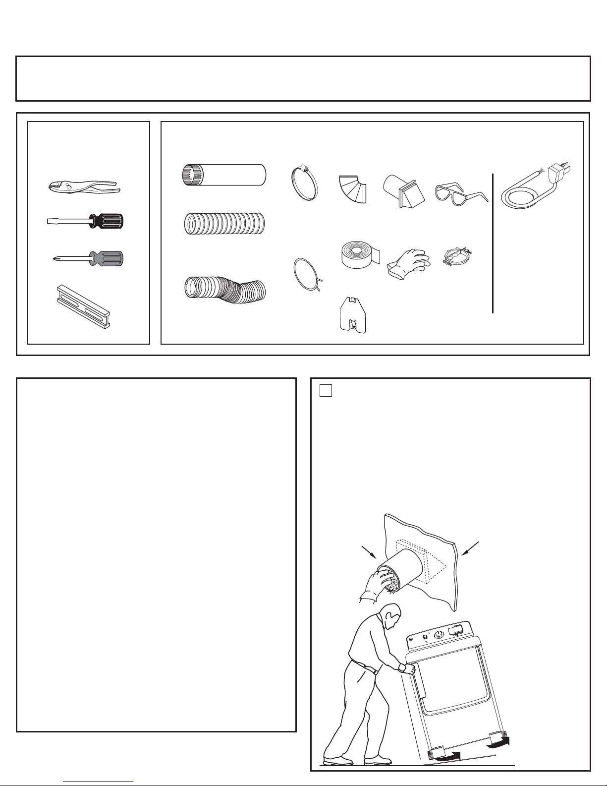
Disconnect dryer from electrical supply.
Wear gloves and arm guards.
Close the back opening with cover plate (Kit WE1M454).
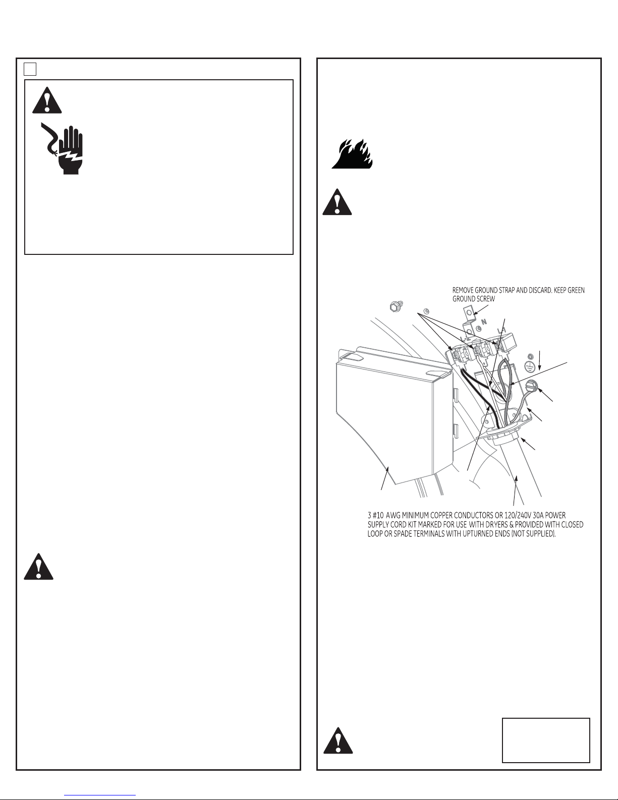
Failure to do so may result in electrical shock
or lacerations.
Electrical Shock
Hazard
?
09%#$),:8,+95(99(*/9/,+7>,78,*:7,2>959/e
structure.
$/,;,493:89459),*544,*9,+95(4>59/,7+:*9;,4957*/034,>
?
Through the rear opening, locate the tab in the middle of
the appliance base. Lift the tab to about 45º using a flat
BEND TAB
UP 45
o
Reconnect the cut portion (A) of the duct to the blower
housing. Make sure that the shortened duct is aligned with
the tab in the base. Use the screw saved previously to secure
RIGHT OR
LEFT SIDE
EXHAUST
PORTION "A"
FIXING
HOLE
TAB LOCATION
ADDING NEW DUCT
the duct in place through the tab on the appliance base.
NOTE: the long vent model (GTDL740EDWW) is capable of
right side, rear and bottom venting only.
blade screwdriver.
WARNING

Installation Instructions
ADDING ELBOW AND DUCT FOR
EXHAUST TO LEFT OR RIGHT SIDE OF
CABINET
-Pr((#"."%++ ).*)'&*))&
ar%*$!% $)
-
%&$ $$%$$))"%+)%)',' $)'$"*)
CAUTION: Be sure not to pull or damage the
electrical wires inside the dryer when inserting the duct.
-&&",*))&((%+$%$)!% $))+$)
',' $)'$"*)$)"%+
ADDING ELBOW FOR EXHAUST
THROUGH BOTTOM OF CABINET
-$('))"%+)'%*)re'%&$ $$%$$)
))%)',' $)'$"*)
-&&",*))&%$)!% $))+$)',' $)'$"
*)$"%+((%+$%$&
PE
CAUTION:
Use 4” rigid metal ducting only
inside the dryer. Internal duct
joints must be secured with
tape, otherwise they may sepa-
rate and cause a safety hazard.
CAUTION:
Internal duct joints
must be secured with
tape, otherwise they
may separate and cause
a safety hazard.
PE
ADDING COVER PLATE TO REAR OF
CABINET (SIDES AND BOTTOM EXHAUST)
Connect standard metal elbows and ducts to complete
the exhaust system. Cover back opening with a plate
(Kit WE1M454) is available from your local service provider.
Place with
PL ATE
(KIT WE1M454)
NEVER LEAVE THE BACK OPENING
WITHOUT THE PLATE.
(Kit WE1M454)
WARNING

WATER
WATER
''Y'' Conector
Installation InstructionsInstallation Instructions

Installation Instructions
2
ABOUT REVERSING THE DOOR
SWING
IMPORTANT NOTES:
· Read the instructions all the way through before starting.
÷+DQGOHSDUWVFDUHIXOO\WRDYRLGVFUDWFKLQJSDLQW
· Set screws down by their related parts to avoid using them in
the wrong places.
÷3URYLGHDQRQVFUDWFKLQJZRUNVXUIDFHIRUWKHGRRU÷1RUPDO
FRPSOHWLRQWLPHWRUHYHUVHWKHGRRUVZLQJLV²PLQXWHV
IMPORTANT:
2QFH\RXEHJLQGRQRWPRYHWKHFDELQHWXQWLOGRRUVZLQJ
UHYHUVDOLVFRPSOHWHG7KHVHLQVWUXFWLRQVDUHIRUFKDQJLQJ
the hinges from the right side to the left side - if you ever
ZDQWWRVZLWFKWKHPEDFNWRWKHULJKWVLGHIROORZWKHVHVDPH
instructions and reverse all references to the left and right.
Tools Needed
6WDQGDUG3KLOOLSV6FUHZGULYHU
7DSHWLSSHGSXWW\NQLIH
6PDOOÀDWEODGHVFUHZGULYHU
Before you start
Unplug the dryer from its
electrical outlet
2SHQWKHGRRUWRDSSUR[LPDWHO\GHJUHHV
:LWKDSXWW\NQLIHUHPRYHWKHSODVWLFFDSVORFDWHG
along the left side of front panel and set them aside.
Remove the bottom screw from each hinge (right side)
and partially insert them into the top left side hinge holes.
NOTE: $OOIURQWSDQHOKLQJHVFUHZVZLOOQRZEHLQWKH
top hinge holes - 2 on the left and 2 on the right.
Plastic Cap (4)
3Loosen the bottom 2 right side hinge screws. Remove
WKHGRRUDQGSODFHLWRQDSURWHFWHGÀDWVXUIDFHWRDYRLG
DQ\GDPDJH5HPRYHERWKWKH%OLQG3ODWHDQGWKH6WULNH
3ODWHDQGLQVWDOOWKHPLQRSSRVLWHSRVLWLRQV
5HPRYHWKHGRRUKLQJHVFUHZVHGJHVFUHZVDQG
LQVLGHVFUHZV/LIWWKHLQQHUGRRUXSZDUGVXVLQJDÀDW
blade screwdriver.
REVERSING THE DOOR
SWING
SOLID DOOR MODELS:
*7'3('::
*7'3*'::
*7'/('::
*7'/*'::

Installation Instructions
:KHQWKHFRYHUFDSVDQGGRRUKDQGOHLQSODFHPRXQW
the inner door back into the outer door with the screws
UHPRYHGLQVWHS0DNHVXUH\RXPRXQWWKHKLQJHVRQ
the side opposite the handle.
Remove and swap the 2 cover caps and door handle
from the outer door:
A. Squeeze the tabs on the inside of the door handle
FOLSV3XVKFOLSVWKURXJKWKHRXWHUGRRU
B. Squeeze the tabs on the inside of the cover caps.
3XVKFDSVWKURXJKWKHRXWHUGRRU
C.3XVKWKHGRRUKDQGOHFOLSVLQWRWKHRSHQLQJVRQWKH
RSSRVLWHVLGHRIWKHRXWHUGRRUPDNLQJVXUH\RXÀLS
the handle so it curves to the inside.
D.3XVKWKHFRYHUFDSVLQWRWKHRSHQLQJVRQWKHRXWHU
door where the handle was removed.
,QVWDOOWKHSODVWLFFDSVUHPRYHGLQVWHSLQWRWKH
right side front panel holes.
NOTE:7RUHWXUQWKHGRRUWRWKHRULJLQDOVHWXSIROORZ
WKHVHLQVWUXFWLRQVVZDSSLQJ´OHIWµDQG´ULJKWµ
Mount the assembled door on the 2 upper left side hinge
screws installed in step 2.
Move the hinge screws loosened in step 3 into the lower
OHIWVLGHVFUHZKROHVDQG¿UPO\WLJKWDOOVFUHZV

Installation Instructions
2
2SHQWKHGRRUWRDSSUR[LPDWHO\GHJUHHV
:LWKDSXWW\NQLIHUHPRYHWKHSODVWLFFDSVORFDWHG
along the left side of front panel and set them aside.
Remove the bottom screw from each hinge (right side)
DQGSDUWLDOO\LQVHUWWKHLQWRWKHWRSOHIWVLGHKLQJHKROHV
NOTE: $OOIURQWSDQHOKLQJHVFUHZVZLOOQRZEHLQWKH
top hinge holes - 2 on the left and 2 on the right.
Plastic Cap (4)
3Loosen the bottom 2 right side hinge screws. Remove
WKHGRRUDQGSODFHLWRQDSURWHFWHGÀDWVXUIDFHWRDYRLG
DQ\GDPDJH5HPRYHERWKWKH%OLQG3ODWHDQGWKH6WULNH
3ODWHDQGLQVWDOOWKHPLQRSSRVLWHSRVLWLRQV
5HPRYHWKHGRRUKLQJHVFUHZVHGJHVFUHZVDQG
LQVLGHVFUHZV/LIWWKHLQQHUGRRUXSZDUGVXVLQJDÀDW
blade screwdriver.
REVERSING THE DOOR SWING
SOLID DOOR MODELS
WITH COVER CAPS:

Installation Instructions
:KHQWKHFRYHUFDSDQGGRRUKDQGOHLQSODFHPRXQW
the inner door back into the outer door with the screws
UHPRYHGLQVWHS0DNHVXUH\RXPRXQWWKHKLQJHVRQ
the side opposite the handle.
Remove and swap the cover cap and door handle from
the outer door:
A. Squeeze the tabs on the inside of the door handle
FOLSV3XVKFOLSVWKURXJKWKHRXWHUGRRU
B. Squeeze the tabs on the inside of the cover cap.
3XVKFDSWKURXJKWKHRXWHUGRRU
C.3XVKWKHGRRUKDQGOHFOLSVLQWRWKHRSHQLQJVRQWKH
RSSRVLWHVLGHRIWKHRXWHUGRRUPDNLQJVXUH\RXÀLS
the handle so it curves to the inside.
D.3XVKWKHFRYHUFDSLQWRWKHRSHQLQJVRQWKHRXWHU
door where the handle was removed.
,QVWDOOWKHSODVWLFFDSVUHPRYHGLQVWHSLQWRWKH
right side front panel holes.
NOTE:7RUHWXUQWKHGRRUWRWKHRULJLQDOVHWXSIROORZ
WKHVHLQVWUXFWLRQVVZDSSLQJ´OHIWµDQG´ULJKWµ
Mount the assembled door on the 2 upper left side hinge
screws installed in step 2.
Move the hinge screws loosened in step 3 into the lower
OHIWVLGHVFUHZKROHVDQG¿UPO\WLJKWDOOVFUHZV

Installation Instructions
2
2SHQWKHGRRUWRDSSUR[LPDWHO\GHJUHHV
:LWKDSXWW\NQLIHUHPRYHWKHSODVWLFFRYHUVORFDWHG
along the left side of front panel and set them aside.
Remove the bottom screw from each hinge (right side)
and partially insert them into the top left side hinge
holes.
NOTE: $OOIURQWSDQHOKLQJHVFUHZVZLOOQRZEHLQWKH
top hinge holes - 2 on the left and 2 on the right.
Plastic Cap (4)
3Loosen the bottom 2 right side hinge screws. Remove the
GRRUDQGSODFHLWRQDSURWHFWHGÀDWVXUIDFHWRDYRLGDQ\
damage.
5HPRYHERWKWKH%OLQG3ODWHDQGWKH6WULNH3ODWHDQG
install them in opposite positions.
5HPRYHWKHGRRUKLQJHVFUHZVHGJHVFUHZVDQG
LQVLGHVFUHZV/LIWWKHLQQHUGRRUXSZDUGVXVLQJDÀDW
blade screwdriver.
REVERSING THE DOOR SWING
GLASS PANEL DOOR MODELS:
*7'6(':6
*7'6*':6
*7'6('0&
*7'6*'0&
*7'6(':6
*7'6*':6
*7'6('0&
*7'6*'0&
*+'6(':6
*+'6*':6
*+'6('0&
*+'6*'0&
*7'6(':6
*7'6*':6
*7'6('0&
*7'6*'0&
*7'6(':6
*7'6*':6
*7'6('0&
*7'6*'0&
Door hinge
screws
Inner door
Outer door
Inside screws
Inside screws
Edge
screws

Installation Instructions
:KHQWKHFRYHUFDSVDQGGRRUKDQGOHLQSODFHPRXQW
the inner door back into the outer door with the screws
UHPRYHGLQVWHS0DNHVXUH\RXPRXQWWKHKLQJHVRQ
the side opposite the handle.
Remove and swap the 2 cover caps and door handle
from the outer door:
A. Squeeze the tabs on the inside of the door handle
FOLSV3XVKFOLSVWKURXJKWKHRXWHUGRRU
B. Squeeze the tabs on the inside of the cover caps.
3XVKFDSVWKURXJKWKHRXWHUGRRU
C.3XVKWKHGRRUKDQGOHFOLSVLQWRWKHRSHQLQJVRQWKH
RSSRVLWHVLGHRIWKHRXWHUGRRUPDNLQJVXUH\RXÀLS
the handle so it curves to the inside.
D.3XVKWKHFRYHUFDSVLQWRWKHRSHQLQJVRQWKHRXWHU
door where the handle was removed.
Edge
screws
Door
hinge
screws
Inside screws
Inside screws
Handle
,QVWDOOWKHSODVWLFFDSVUHPRYHGLQVWHSLQWRWKH
right side front panel holes.
NOTE:7RUHWXUQWKHGRRUWRWKHRULJLQDOVHWXSIROORZ
WKHVHLQVWUXFWLRQVVZDSSLQJ´OHIWµDQG´ULJKWµ
Mount the assembled door on the 2 upper left side hinge
screws installed in step 2.
Move the hinge screws loosened in step 3 into the lower
OHIWVLGHVFUHZKROHVDQG¿UPO\WLJKWDOOVFUHZV
Other manuals for GTDS850EDWS
1
This manual suits for next models
25
Table of contents
Other GE Dryer manuals

GE
GE DWXR483GG Manual

GE
GE DDE5100M User manual

GE
GE DLSR483GG Manual

GE
GE GFDS170GH1WW User manual

GE
GE GE Profile Prodigy DPSR483EAAA User manual

GE
GE DCVH680GJMR Manual

GE
GE DCVH640GJ Manual

GE
GE DPSR610EGWT - Profile 7.0 cu. Ft. Electric... Manual

GE
GE DDE7209R Installation instructions

GE
GE DCVH640 User manual
Popular Dryer manuals by other brands

Alliance Laundry Systems
Alliance Laundry Systems LES33AW operating instructions

Siemens
Siemens WP30A2X0HK user manual

Heinner
Heinner HHPD-80A++ instruction manual

Oras
Oras 583120 Installation and maintenance guide

Frigidaire
Frigidaire GLER331CA Factory parts catalog

American Dryer Corp.
American Dryer Corp. ML-175 parts manual