GE GTDL200GM1WW User manual

Installation J GasDrger l@ ®
Instructions 08
Questions on Installation? Call: 800.GE.CARES (US) or 800-561-3344 (Canada) J
or visit our web site at: www.GEAppliances.corn (US) I
BEFORE YOU BEGIN
Read these instructions
completely and carefully.
• IMPORTANT- save
these instructions for local
inspector's use.
• IMPORTANT- Observe
all governing codes and
ordinances.
• Note to Installer - Be sure to
leave these instructions with
the customer.
• Note to Customer- Keep these
instructions with your Owner's
Manual for future reference.
• Before the old dryer is removed
from service or discarded,
remove the dryer door.
•Inspect the dryer exhaust
outlet and straighten the
outlet walls if they are bent.
• Service information and the
wiring diagram are located in
the control console.
• Do not allow children on
or in the appliance. Close
supervision of children is
necessary when the appliance
is used near children.
• Install the dryer where the
temperature is above 50°F for
satisfactory operation of the
dryer control system.
• Product failure due to
improper installation is not
covered under the Warranty.
TOOLS YOU WILL NEED
(x2)
10"ADJUSTABLEWRENCHES SLIPJOINTPLIERS
R" DID_ \AI_EICH FLATBLADESCREWDRIVER
WARNING RISKOF FIRE
• To reduce the risk of severe injury or death, follow all installation instructions.
• Clothes dryer installation must be performed by a qualified installer.
• Install the clothes dryer according to these instructions and in accordance with local
codes.
• California Safe Drinking Water and Toxic Enforcement Act
This act requires the governor of California to publish a list of substances known to the
state to cause cancer, birth defects or other reproductive harm and requires businesses
to warn customers of potential exposure to such substances. Gas appliances can
cause minor exposure to four of these substances, namely benzene, carbon monoxide,
formaldehyde and soot, caused primarily by the incomplete combustion of natural gas
or LP fuels. Properly adjusted dryers will minimize incomplete combustion. Exposure to
these substances can be minimized further by properly venting the dryer to the outdoors.
• This dryer must be exhausted to the outdoors.
• Use only rigid metal 4" diameter ductwork inside the dryer cabinet and use only UL
approved transition ducting between the dryer and the home duct.
• DO NOT install a clothes dryer with flexible plastic ducting materials. If flexible metal
(semirigid or foil-type) duct is installed, it must be UL listed and installed in accordance
with the instructions found in "Connecting The Dryer To House Vent" on page 5 of this
manual. Flexible venting materials are known to collapse, be easily crushed, and trap
lint. These conditions will obstruct dryer airflow and increase the risk of fire.
• Do not install or store this appliance in any location where it could be exposed to water
and or weather.
• Save these instructions. (Installers: Be sure to leave these instructions with the
customer).
IN THE COMMONWEALTH OF MASSACHUSETTS
•This product must be installed bLIalicensed plumber or gas fitter.
• When using ball-type gas shut-off valves, they shall be the T-handle tLIpe.
• A flexible gas connector, when used, most not exceed 3 feet.
4"DIA.METALDUCT
(RECOMMENDED}
4"DIA.FLEXIBLEMETAL(SEMFRIGID}
ULLISTEDTRANSITIONDUCT
(IFNEEDED}
KiTWXO8X10077(iNCLUDES2ELBOWS}
4"DIA.FLEXIBLEMETAL(FOILTYPE}
ULLISTEDTRANSITIONDUCT
(IFNEEDED,}
MATERIALS YOU WILL NEED
%
4"DIA.METAL
ELBOW
4"DUCT
EXHAUST
HOOD
PIPE
COMPOUND SOAPSOLUTION
FORLEAKDETECTION
CLAMPS(2}
OR
4"SPRING
CLAMPS(2}
DUCTTAPE SAFETY
GLASSES
FLEXIBLEGASLINECONNECTOR GLOVES
Step i
Step 2
Step 3
Step 4
Step 5
Step 6
Step 7
Step 8
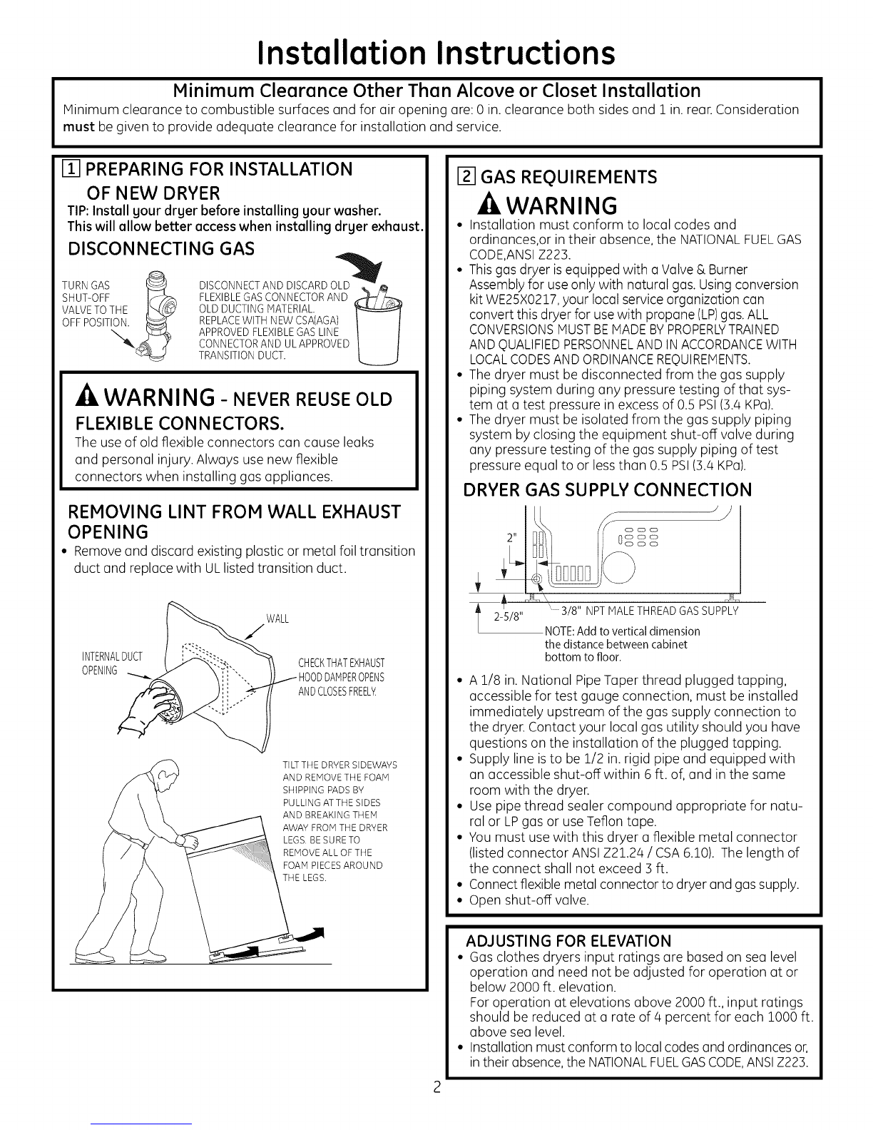
Verify your gas installation (seesection 2).
Prepare the area and exhaust for installation of new dryer
(seesection 1).
Check and ensure the existing external exhaust is clean (see
section 1)and meets attached installation specifications (see
section 6).
Remove the foam shipping pads (seesection 1).
Move the dryer to the desired location.
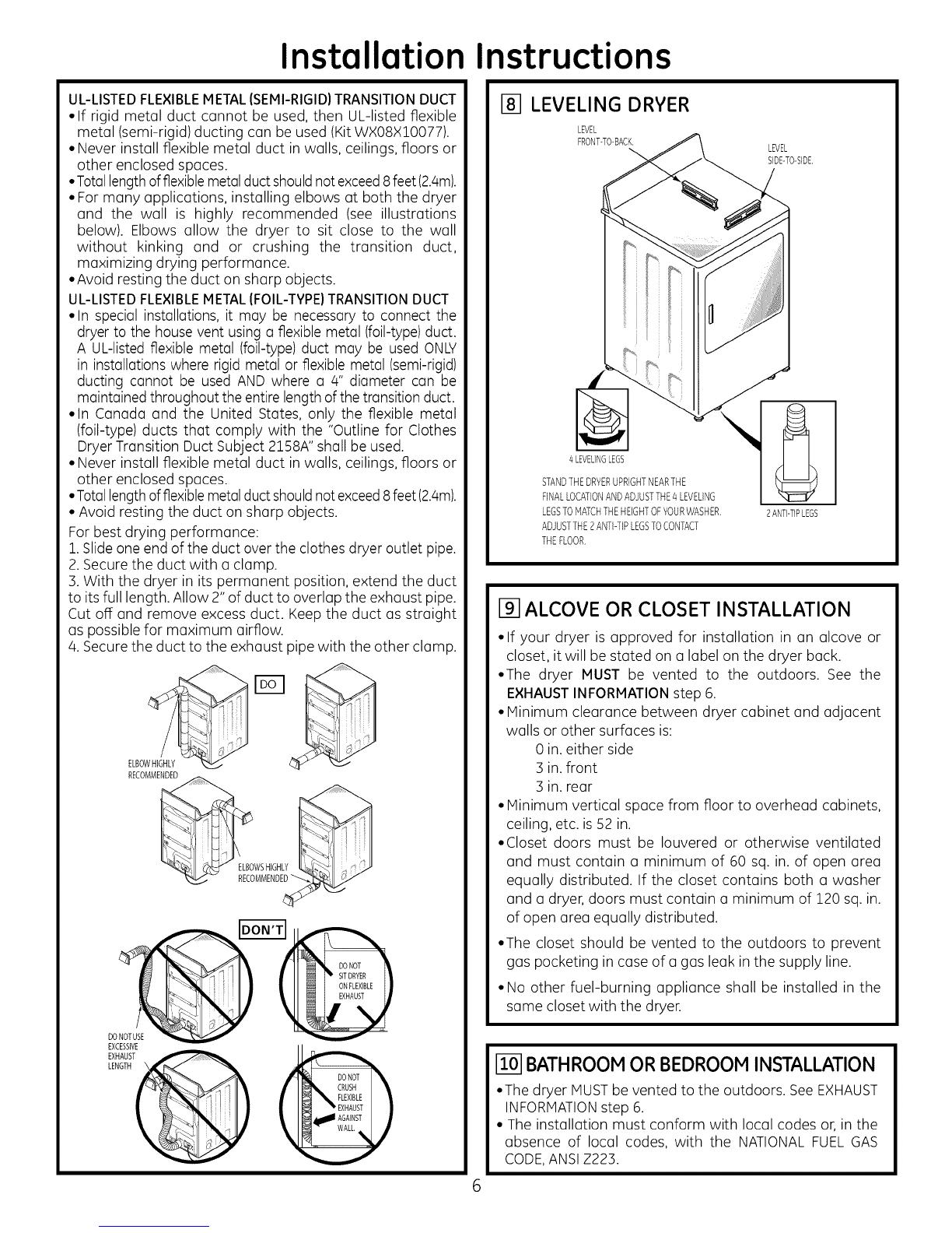
Level your dryer (seesection 8).
Connect the gas supply (seesection 3) and check for leaks
(seesection 4).
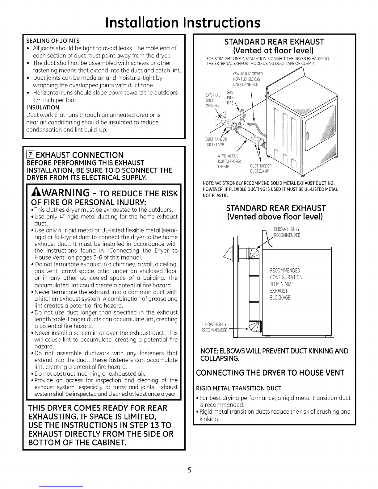
Connect the external exhaust (seesection 7).
Step 9 Connect the power supply (seesection 5).
Step 10Check the operation of the power supply, gas connections,
and venting.
Step 11Place the Owner's Manual and the Installation Instructions in
a location where they will be noticed by the owner.
For alcove or closet installation, see section 9.
For bathroom or bedroom installation, see section 10.
For mobile or manufactured home, see section 11.
For garage installation (if allowed by local codes), see section 12.
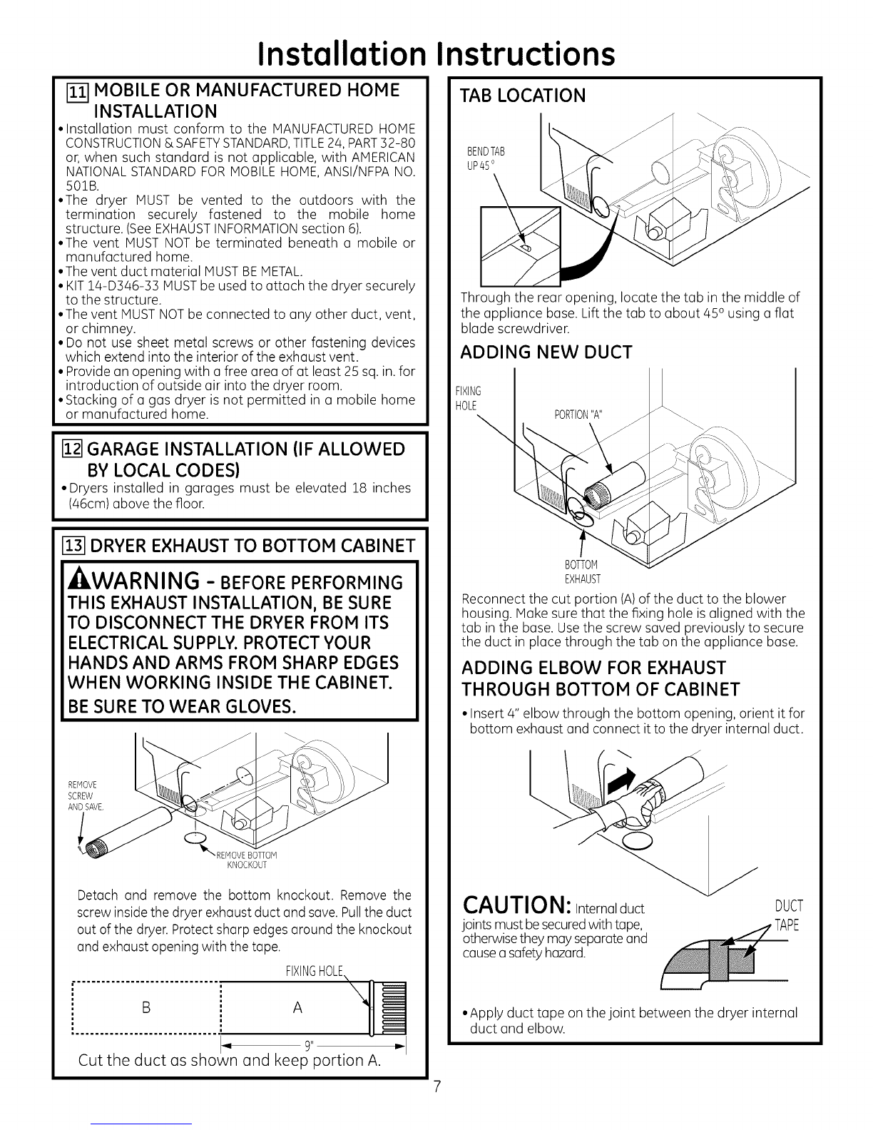
For side or bottom exhaust, see section 13.
234D1582PO08 31-16679 03-12 GE

Installation Instructions
Minimum Clearance Other Than Alcove or Closet Installation
Minimum clearance to combustible surfaces and for air opening are: 0 in.clearance both sides and 1 in. rear.Consideration
must be given to provide adequate clearance for installation and service.
m PREPARING FOR INSTALLATION
OF NEW DRYER
TIP:Install your dryer before installing your washer.
This will allow better access when installing dryer exhaust.
DISCONNECTING GAS
TURNGAS _ DISCONNECTANDDISCARDOLu_ _
SHUT-OFF Js_-._ FLEXIBLEGASCONNECTORAND ,_
VALVETOTHE _ OLD DUCTINGMATERIAL.
APPROVEDFLEXIBLEGASLINE
CONNECTORAND ULAPPROVED
TRANSITIONDUCT.
WARNING - NEVERREUSEOLD
FLEXIBLE CONNECTORS.
The use of old flexible connectors can cause leaks
and personal injury. Always use new flexible
connectors when installing gas appliances.
REMOVING LINT FROM WALL EXHAUST
OPENING
• Removeand discard existing plastic or metal foil transition
duct and replace with ULlisted transition duct.
WALL
/
INTERNALDUCT CHECKTHATEXHAUST
OPENING IDDAMPEROPENS
ANDCLOSESFREEL_
TILTTHE DRYERSIDEWAYS
AND REMOVETHE FOAM
SHIPPING PADS BY
PULLING ATTHE SIDES
AND BREAKINGTHEM
AWAY FROM THE DRYER
LEGS. BESURE TO
REMOVEALL OF THE
FOAM PIECESAROUND
THE LEGS.
[] GAS REQUIREMENTS
WARNING
• Installation must conform to local codes and
ordinances,or in their absence, the NATIONALFUELGAS
CODE,ANSIZ223.
• This gas dryer isequipped with a Valve & Burner
Assembly for useonly with natural gas. Using conversion
kit WE25X0217,your local service organization can
convert this dryer for usewith propane (LP)gas. ALL
CONVERSIONSMUSTBEMADEBYPROPERLYTRAINED
AND QUALIFIEDPERSONNELAND IN ACCORDANCEWITH
LOCALCODESAND ORDINANCEREQUIREMENTS.
• The dryer must be disconnected from the gas supply
piping system during any pressure testing of that sys-
tem at a test pressure in excess of 0.5 PSI(3.4 KPa).
• The dryer must be isolated from the gas supply piping
system by closing the equipment shut-off valve during
any pressure testing of the gas supply piping of test
pressure equal to or less than 0.5 PSI(3.4 KPa).
DRYER GAS SUPPLY CONNECTION
' 3/8" NPT MALETHREADGASSUPPLY
NOTE:Add to vertical dimension
the distance between cabinet
bottom to floor.
• A 1/8 in. National Pipe Taper thread plugged tapping,
accessible for test gauge connection, must be installed
immediately upstream of the gas supply connection to
the dryer. Contact your local gas utility should you have
questions on the installation of the plugged tapping.
• Supply line isto be 1/2 in.rigid pipe and equipped with
an accessible shut-off within 6 ft. of, and in the same
room with the dryer.
• Use pipe thread sealer compound appropriate for natu-
ral or LPgas or use Teflon tape.
• You must use with this dryer a flexible metal connector
(listed connector ANSIZ21.24 /CSA6.10). The length of
the connect shall not exceed 3 ft.
• Connectflexible metal connector to dryer and gassupply.
• Open shut-off valve.
ADJUSTING FOR ELEVATION
• Gas clothes dryers input ratings are based on sea level
operation and need not be adjusted for operation at or
below 2000 ft. elevation.
For operation at elevations above 2000 ft., input ratings
should be reduced at a rate of 4 percent for each 1000 ft.
above sea level.
• Installation must conform to localcodes and ordinances or,
in their absence,the NATIONALFUELGASCODE,ANSIZ223.

Installation Instructions
RECONNECTING GAS
Listed connector ANSI Z2!.24 /CSA 6.!0
1/8" NPTPIPE
PLUGFOR
NEWMETAL GAS
FLEXIBLEGAS INLETPRESSURE
LINECONNECTOR
ADAPTER SHUT-OFF
3/8" NPT VALVE
ELBOW __ PIPESIZE
ITEMSNOTSUPPLIED AT LEAST1/2"
NOTE:The connector ond fittings (]re designed for use
only on the originol instollotion ond (]re not to be reused
for onother opplionce or ot onother Iocotion. Keepfiore
end of °doptor free of greose, oil ond threod seolont.
CAUTION: UseodoptorsosshownConnector
nuts must not be connected directly to pipe threads.
\
APPLYPIPECOMPOUND
TOTHEADAPTERAND
DRYERGASINLET.
Tighten the flexible
gas line using two
adjustable wrenches.
I
APPLYPIPECOMPOUND
TOALL MALETHREADS.
Tighten oil connections using two adjustable
wrenches. Do not overtorque gas connections!
14]LEAK TEST
_ZLWARNING- NEVER USE AN OPEN
FLAME TO TEST FOR GAS LEAKS.
OPEN
GASVALVE.
Check all connections for leaks with soupy solution or
equivalent. Apply soup solution. Leek test solution must
not contain ammonia which could cause damage to the
brass fittings. If leaks are found, close valve, retighten the
joint, and repeat the soup test.

Installation Instructions
151ELECTRICALCONNECTION INFORMATION
WARNING - TOREDUCETHE
RISK OF FIRE, ELECTRICAL SHOCK, AND
PERSONAL INJURY:
• DO NOT USE AN EXTENSION CORD
OR AN ADAPTER PLUG WITH THIS
APPLIANCE.
Dryer must be electrically grounded in accordance
with local codes and ordinances, or in the absence
of local codes, in accordance with the NATIONAL
ELECTRICALCODE,ANSI/NFPANO.70.
ELECTRICAL REQUIREMENTS
This appliance must be supplied with 120V,60Hz, end
connected to oproperlg grounded branch circuit, pro-
tected by e15- or 20-amp circuit breaker or time deleg
fuse. If electrical supplg provided does not meet the
above specifications, it is recommended that alicensed
electrician install an approved outlet.
ZkWARNING - THISDRYERIS
EQUIPPED WITH A THREE-PRONG
(GROUNDING) PLUG FOR YOUR
PROTECTION AGAINST SHOCK HAZARD
AND SHOULD BE PLUGGED DIRECTLY
INTO A PROPERLY GROUNDED THREE-
PRONG RECEPTACLE. DO NOT CUT OR
REMOVE THE GROUNDING PRONG
FROM THIS PLUG.
ENSURE PROPER GROUND EXISTS BEFORE USE
IF LOCAL CODES PERMIT,
AN EXTERNALGROUND WIRE
(NOT PROVIDED),WHICH rV]EETS
LOCAL CODES, rvlAYBEADDED
BYATTACHING TO THE GREEN
GROUND SCREW ON THE REAR
OF THE DRYER,AND TO A GROUNDED
rVlETALCOLD WATER PIPEOR OTHER
ESTABLISHED GROUND.
[] EXHAUST INFORMATION
,AWARNING -IN CANADAANDINTHE
UNITED STATES, THE REQUIRED EXHAUST
DUCT DIAMETER IS 4in (102mm). DO NOT
USE DUCT LONGER THAN SPECIFIED IN THE
EXHAUST LENGTH TABLE.
Using exhaust longer than specified length will:
• Increase the drying times and the energy cost.
• Reduce the dryer life.
• Accumulate lint, creating a potential fire hazard.
The correct exhaust installation is YOUR
RESPONSIBILITY.Problems due to incorrect
installation are not covered by the warrantg.
Remove and discard existing plastic or metal foil
transition duct and replace with UL listed transition duct.
The MA×IMUM ALLOWABLEduct length and number of
bends of the exhaust system depends upon the type of
duct, number of turns, the type of exhaust hood (wall
cap), and all conditions noted below. The maximum duct
length for rigid metal duct isshown in the table below.
No. of 90 °
Elbows
0
1
2
3
4
5
EXHAUST LENGTH
RECOMMENDEDMAXIMUM LENGTH
Exhaust Hood Types
Use only for short
Recommended run installations
Rigid
Metal
150 Feet
135 Feet
125 Feet
125 Feet
105 Feet
95 Feet
4" DIA.
_-!12"
Rigid
Metal
125 Feet
125 Feet
105 Feet
95 Feet
85 Feet
75 Feet
EXHAUST SYSTEM CHECK LIST
HOOD ORWALL CAP
• Terminate in a manner to prevent back drafts or entry of
birds or other wildlife.
• Termination should present minimal resistance to
the exhaust air flow and should require little or no
maintenance to prevent clogging.
• Never install a screen in or over the exhaust duct. This
could cause lint build up.
• Wall caps must be installed at least 12in. above ground
level or any other obstruction with the opening pointed
down.
SEPARATIONOFTURNS
For best performance, separate all turns by at least a,ft.
of straight duct, including distance between last turn and
exhaust hood.
TURNSOTHERTHAN 90°
• One turn of 45oor less may be ignored.
• Two 45° turns should be treated as one 900turn.
• Eachturn over/45 ° should be treated as one 900 turn.

Installation Instructions
SEALING OFJOINTS
• Alljoints should be tight to avoid leaks.The male end of
each section of duct must point away from the dryer.
• The duct shall not be assembled with screws or other
fastening means that extend into the duct and catch lint.
• Ductjoints can be made air and moisture-tight by
wrapping the overlapped joints with duct tape.
• Horizontal runs should slope down toward the outdoors
1/4 inch per foot.
INSULATION
Duct work that runs through an unheated area or is
near air conditioning should be insulated to reduce
condensation and lint build-up.
F-f]EXHAUST CONNECTION
BEFORE PERFORMING THIS EXHAUST
INSTALLATION, BE SURE TO DISCONNECT THE
DRYER FROM ITS ELECTRICAL SUPPLY.
- WARNING - TO REDUCE THE RISK
OF FIRE OR PERSONAL INJURY:
• This clothes dryer must be exhausted to the outdoors.
• Use only 4" rigid metal ducting for the home exhaust
duct.
• Use only 4" rigid metal or UL-listed flexible metal (semi-
rigid or foil-type) duct to connect the dryer to the home
exhaust duct. It must be installed in accordance with
the instructions found in "Connecting the Dryer to
House Vent" on pages 5-6 of this manual.
• Do not terminate exhaust in a chimney, a wall, a ceiling,
gas vent, crawl space, attic, under an enclosed floor,
or in any other concealed space of a building. The
accumulated lint could create a potential fire hazard.
• Never terminate the exhaust into a common duct with
a kitchen exhaust system. A combination of grease and
lint creates a potential fire hazard.
• Do not use duct longer than specified in the exhaust
length table. Longer ducts can accumulate lint, creating
a potential fire hazard.
• Never install a screen in or over the exhaust duct. This
will cause lint to accumulate, creating a potential fire
hazard.
• Do not assemble ductwork with any fasteners that
extend into the duct. These fasteners can accumulate
lint, creating apotential fire hazard.
• Do not obstruct incoming or exhausted air.
• Provide an access for inspection and cleaning of the
exhaust system, especially at turns and joints. Exhaust
systemshallbe inspectedand cleaned at leastonceu year.
THIS DRYER COMES READY FOR REAR
EXHAUSTING. IF SPACE IS LIMITED,
USE THE INSTRUCTIONS IN STEP 13 TO
EXHAUST DIRECTLY FROM THE SIDE OR
BOTTOM OF THE CABINET.
STANDARD REAR EXHAUST
(Vented at floor level)
FOR STRAIGHT LINE INSTALLATION, CONNECT THE DRYER EXHAUST TO
THE EXTERNAL EXHAUST HOOD USING DUCT TAPE OR CLAIVlR
CSAIAGA}APPROVED
NEWFLEXIBLEGAS
LINECONNECTOR
GAS
EXTERNAL INLET
DUCT PIPE
OPENING
DUCTTAPEOR
DUCTCLAMP
4"NETALDUCT
(CUTTOPROPER
LENGTH} DUCTTAPEOR
DUCTCLAHP
NOTE: WE STRONGLYRECOMMEND SOLID METAL EXHAUST DUCTtNG.
HOWEVER, IF FLEXIBLEDUCTtNG IS USED IT MUST BEUL-LISTED METAL
NOT PLASTIC.
STANDARD REAR EXHAUST
(Vented above floor level)
ELBOWHIGHLY
RECOMMENDED"
ELBOWHIGHLY
"_.._ RECOMMENDED
RECOMMENDED
CONFIGURATION
TOMINIMIZE
EXHAUST
BLOCKAGE.
NOTE: ELBOWS WILL PREVENT DUCT KINKING AND
COLLAPSING.
CONNECTING THE DRYERTO HOUSE VENT
RIGID METAL TRANSITION DUCT
• For best drying performance, a rigid metal transition duct
is recommended.
• Rigidmetal transition ducts reduce the risk of crushing and
kinking.

Installation Instructions
UL-LISTEDFLEXIBLEMETAL(SEMI-RIGID)TRANSITIONDUCT
• If rigid metal duct cannot be used, then UL-listed flexible
metal (semi-rigid) ducting can be used (Kit WXO8XlO077).
• Never install flexible metal duct in walls, ceilings, floors or
other enclosed spaces.
• Totallengthofflexiblemetalduct shouldnotexceed8feet (2.4m).
• For many applications, installing elbows at both the dryer
and the wall is highly recommended (see illustrations
below). Elbows allow the dryer to sit close to the wall
without kinking and or crushing the transition duct,
maximizing drying performance.
•Avoid resting the duct on sharp objects.
UL-LISTEDFLEXIBLEMETAL(FOIL-TYPE)TRANSITIONDUCT
• In special installations, it may be necessary to connect the
dryer to the housevent using a flexible metal (foil-type)duct.
A UL-listedflexible metal (foil-type)duct may be used ONLY
in installations where rigid metal or flexible metal (semi-rigid)
ducting cannot be used AND where a 4" diameter can be
maintained throughout the entire lengthof the transition duct.
• In Canada and the United States, only the flexible metal
(foil-type) ducts that comply with the "Outline for Clothes
Dryer Transition Duct Subject 2158A" shall be used.
• Never install flexible metal duct in walls, ceilings, floors or
other enclosed spaces.
• Totallengthofflexiblemetalduct shouldnotexceed8feet (2.4m).
• Avoid resting the duct on sharp objects.
For best drying performance:
1.Slideone end of the duct over the clothes dryer outlet pipe.
2.Secure the duct with a clamp.
3.With the dryer in its permanent position, extend the duct
to its full length. Allow 2" of duct to overlap the exhaust pipe.
Cut off and remove excess duct. Keep the duct as straight
as possible for maximum airflow.
4.Secure the duct to the exhaust pipe with the other clamp.
ELBOWHIGHLY
RECOMMENDED
_WS HIGHLY
- RECOMMENDE_
DO
EXCESSIVE
EXHAUST
LENGTH
[] LEVELING DRYER
LEVEL
FRONT-TO-BACK. LEVEL
SIDE-TO-SIDE
4 LEVELINGLEGS
STANDTHEDRYERUPRIGHTNEARTHE
FINALLOCATIONANDADJUSTTHE4LEVELING
LEGSTOHATCHTHEHEIGHTOFYOURWASHER,
ADJUSTTHE2ANTI-TIPLEGSTOCONTACT
THEFLOOR,
2 ANTI-TIPLEGS
[] ALCOVE OR CLOSET INSTALLATION
•If your dryer is approved for installation in an alcove or
closet, it will be stated on a label on the dryer back.
•The dryer MUST be vented to the outdoors. See the
EXHAUSTINFORMATIONstep 6.
• Minimum clearance between dryer cabinet and adjacent
walls or other surfaces is:
0 in.either side
3in.front
3 in. rear
• Minimum vertical space from floor to overhead cabinets,
ceiling, etc. is 52 in.
•Closet doors must be Iouvered or otherwise ventilated
and must contain a minimum of 60 sq. in. of open area
equally distributed. If the closet contains both a washer
and a dryer, doors must contain a minimum of 120 sq. in.
of open area equally distributed.
•The closet should be vented to the outdoors to prevent
gas pocketing in case of a gas leak in the supply line.
• No other fuel-burning appliance shall be installed in the
same closet with the dryer.
Fi-61BATHROOM OR BEDROOM INSTALLATION
• The dryer MUSTbe vented to the outdoors. See EXHAUST
INFORMATIONstep 6.
• The installation must conform with local codes or, in the
absence of local codes, with the NATIONAL FUELGAS
CODE,ANSIZ223.

Installation Instructions
[] MOBILE OR MANUFACTURED HOME
INSTALLATION
• Installation must conform to the MANUFACTUREDHOME
CONSTRUCTION& SAFETYSTANDARD,TITLE24, PART:32-80
or, when such standard is not applicable, with AMERICAN
NATIONALSTANDARDFORMOBILE HOME,ANSI/NFPANO.
50lB.
•The dryer MUST be vented to the outdoors with the
termination securely fastened to the mobile home
structure. (SeeEXHAUSTINFORMATIONsection 6).
•The vent MUSTNOT be terminated beneath a mobile or
manufactured home.
•The vent duct material MUSTBEMETAL.
• KIT14-D346-33 MUSTbe used to attach the dryer securely
to the structure.
• The vent MUSTNOTbe connected to any other duct, vent,
or chimney.
• Do not use sheet metal screws or other fastening devices
which extend into the interior of the exhaust vent.
• Provide an opening with a free area of at least 25 sq. in.for
introduction of outside air into the dryer room.
• Stacking of a gas dryer is not permitted in a mobile home
or manufactured home.
I_l GARAGE INSTALLATION (IF ALLOWED
BY LOCAL CODES)
• Dryers installed in garages must be elevated 18 inches
(46cm) above the floor.
[] DRYER EXHAUST TO BOTTOM CABINET
-ZiWARNING-BEFOREPERFORMING
THIS EXHAUST INSTALLATION, BE SURE
TO DISCONNECT THE DRYER FROM ITS
ELECTRICAL SUPPLY. PROTECT YOUR
HANDS AND ARMS FROM SHARP EDGES
WHEN WORKING INSIDE THE CABINET.
BE SURE TO WEAR GLOVES.
REMOVE
SCREW
AND SAVE,
(:_'\REMOVEBOTFOM
KNOCKOUT
Detach and remove the bottom knockout. Remove the
screw insidethe dryer exhaust duct and save.Pullthe duct
out of the dryer.Protect sharp edges around the knockout
and exhaust opening with the tape.
FIXINGHOLEs
14 "
Cut the duct as shown and keep portion A.
TAB LOCATION
BENDTAB
UP45°
Through the rear opening, locate the tab in the middle of
the appliance base. Lift the tab to about 450 using a flat
blade screwdriver.
ADDING NEW DUCT
FIXING
HOLE PORTION"A"
BOTTOM
EXHAUST
Reconnect the cut portion (A)of the duct to the blower
housing. Make sure that the fixing hole is aligned with the
tab in the base. Use the screw saved previously to secure
the duct in place through the tab on the appliance base.
ADDING ELBOW FOR EXHAUST
THROUGH BOTTOM OF CABINET
• Insert 4" elbow through the bottom opening, orient it for
bottom exhaust and connect it to the dryer internal duct.
CAUTIO N:Internalduct
jointsmustbesecuredwithtape,
otherwisetheymay separateand
causea safety hazard.
DUCT
•Apply duct tape on the joint between the dryer internal
duct and elbow.

Installation Instructions
ADDING DUCT FOR EXHAUST THROUGH
BOTTOM OF CABINET
• Insert the 4" straight duct in the elbow end hanging out
of the dryer bottom. Wrap duct tape around the joint.
CAUTION: Be sure not to pullor demege the
electrical wires inside the dryer when inserting the duct.
ADDING COVER PLATE TO REAR OF
CABINET
Connect standard metal elbows and ducts to complete
the exhaust system. Cover buck opening with a plate (Kit
WE1M454) available from your local service provider. Place
dryer in final locution.
-_WARNING-NEVER LEAVE THE
BACK OPENING WITHOUT THE PLATE
(KIT WEIM454).
[] CHANGING DIRECTION OF DOOR
OPENING REMOVE/4HOLEPLUGSAND
REMOVE/4 PLACETHEMINTHEHOLES
HINGESCREWS, ONTHEOPPOSITESIDE,
ROTATEDOOR180°
ANDREINSTALL.
i_ISERVICING
-_kWARN ING-LABEL ALL WIRES
PRIOR TO DISCONNECTING WHEN
SERVICING CONTROLS. WIRING
ERRORS CAN CAUSE IMPROPER AND
DANGEROUS OPERATION AFTER
SERVICING/INSTALLATION.
REGISTER YOUR NEW APPLIANCE TO RECEIVE ANY
IMPORTANT PRODUCT NOTIFICATIONS.
Please go to www.GEAppliances.com or moil in
your product registration card.
For questions on installation, coil: 800.626.2000 (US)or
800-561-3344 (Canada).
Table of contents
Other GE Dryer manuals
Popular Dryer manuals by other brands

AirTek
AirTek SC Series Operator's manual

Siemens
Siemens WT47W580AU/01 Installation and operating instructions

Alliance Laundry Systems
Alliance Laundry Systems Speed Queen DF7000WG user guide

Asko
Asko DC7573 operating instructions

Electrolux
Electrolux TWGL5IE300 user manual

Kenmore
Kenmore 110.60372710 Use & care guide