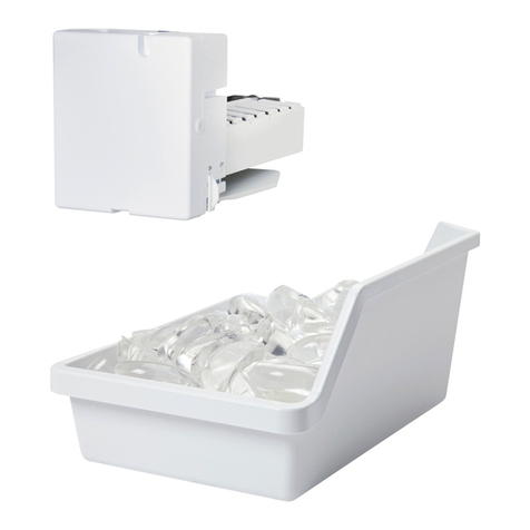
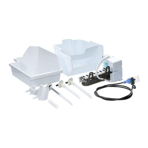
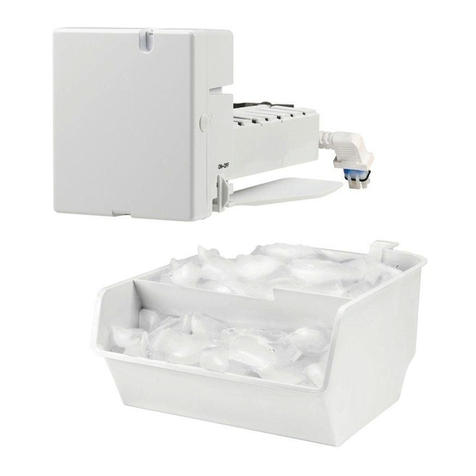
GE Electronic Icemaker How to use

Electronic Icemaker
GE Consumer Home Services Training
TECHNICAL SERVICE GUIDE
Pub # 31-9063 8/00

CAUTION
To avoid personal injury, disconnect power before servicing this
product. If electrical power is required for diagnosis or test
purposes, disconnect the power immediately after performing the
necessary checks.
!
IMPORTANT SAFETY NOTICE
The information in this service guide is intended for use by
individuals possessing adequate backgrounds of electrical,
electronic and mechanical experience. Any attempt to repair a
major appliance may result in personal injury and property
damage. The manufacturer or seller cannot be responsible for the
interpretation of this information, nor can it assume any liability in
connection with its use.
RECONNECT ALL GROUNDING DEVICES
If grounding wires, screws, straps, clips, nuts, or washers used
to complete a path to ground are removed for service, they must
be returned to their original position and properly fastened.
GE Consumer Home Services Training
Technician Service Guide
Copyright © 2000
All rights reserved. This service guide may not be reproduced in whole or in part
in any form without written permission from the General Electric Company.

1
POWER LED
MAGNET 1 MAGNET 2
The control board contains two sensors
(Hall effect sensors), that are similar to an
electronic reed switch. The sensors are
activated by magnets and are used to assist
in controlling icemaker operation. One
magnet, attached to the end of the ejector
arm, allows the control board to use magnetic
sensing to determine if the motor has reached
the home position. The second magnet,
located on the ice sensing arm (feeler arm),
lets the control know whether the arm has
reached a fully extended position.
The on-off rocker switch allows the
icemaker to be turned off. When the switch
is set to on, a green LED on the right side of
the cover will light to show power is on. The
LED is also used to indicate certain icemaker
fault conditions, such as an open or shorted
thermistor, or a harvest cycle longer than 30
minutes. When a fault occurs, the LED will
blink 1/2 second on, 1/2 second off indefinitely
until the icemaker is turned off.
Electronic Icemaker
Beginning in the Spring 2001, a newly
designed icemaker will be introduced in
several refrigerators. This service guide will
help you become familiar with the icemaker
and its operation.
The icemaker contains several new and
innovative features. It has an electronic
control board, an on-off switch, a seven ice
cube mold, a lever style feeler arm and a
thermistor to monitor temperature.
To access the
control board and
other components
within the icemaker,
lift and remove the
plastic plug at the top
of the cover. Remove
the Phillips screw
holding the cover in
place.
The control board is held in place by three
Phillips screws. All wiring is connected to the
board by plug-on terminals.

2
FULLY EXTENDED
FEELER ARM
THERMISTOR
SPRING
PHILLIPS
SCREW
Freeze
The “Freeze” cycle is the period where
the icemaker is waiting for the cubes to freeze
solid. This period of time is based on an
algorithm programmed into the electronic
control. The control makes these calculations
once per second and takes into account the
thermistors current resistance value and the
rate of resistance change. As a result, freeze
times vary based on refrigerator control settings
and environmental conditions (door openings,
room temperature, etc.) but average
approximately 75 minutes for each drop of 7
ice cubes.
Harvest
The “Harvest” cycle will begin when the
freeze algorithm has been satisfied and the arm
is in the “out” or “fully extended” position. If the
arm is in the “in” position when harvest is to
begin, a delay of 3 minutes will be added once
the arm moves to the extended position. This
3 minute delay allows drawer type ice buckets
to be removed for up to 3 minutes without
starting a harvest. The 3 minute delay will begin
again if the arm goes back to the “in” position
anytime during the delay period. The arm is
spring loaded and will go to the out position
unless it is being held in position by an obstacle
such as an ice cube.
At the start of the harvest cycle, the mold heater
will be turned on. One second later, the motor
will start. The heater will remain on until the
mold temperature is above 35.6°F (2°C) and a
The feeler arm moves horizontally. A full
ice bucket will prevent the arm from moving out
to the fully extended position, stopping the next
harvest cycle until ice cubes are removed and
the arm is able to swing out completely
The thermistor is mounted in the mold body,
directly behind the control housing. The
thermistor provides two functions: to measure
the ice temperature during freezing and for
water level detection during fill.
The normal icemaker sequence is to fill the
mold with water, wait until the water is frozen,
harvest the ice and then repeat the cycle. To
accomplish this, three cycles are programmed
in the electronic control: Freeze, Harvest and
Water Fill. The control also contains a Power-
On Diagnostic Test mode, a Harvest Fix mode,
a Fault mode and a Service Diagnostic Test
mode.

3
minimum of 20 seconds have elasped. If
necessary, the heater will cycle with a turn on
temperature of 32°F (0°C) and a turn off
temperature of 35.6°F (2°C)
To insure the motor completes a full
revolution, the control checks to see the motor
is “not home” for at least 10 seconds and the
feeler arm is “in” for at least 10 seconds. Once
these two conditions are met and the motor
reaches home position, the harvest cycle will
be complete and the motor will turn off.
The harvest cycle consists of one
complete revolution of the ejector to sweep the
cubes from the mold and drop them into the
ice bucket. If the harvest cycle is not complete
within 7 minutes, the control will assume that a
cube is blocking the completion of a cycle and
will initiate a harvest fix mode. If the harvest
cycle is not complete within 30 minutes, the
control will assume some other problem has
occurred and will enter the fault mode.
Harvest Fix
If the harvest cycle is not complete
within 7 minutes, the control will enter a “Harvest
Fix” mode. In the harvest fix mode, the
temperature of the mold will be raised in an
attempt to melt any cubes that are jammed. The
control will turn the heater off when the
thermistor temperature reaches 68°F (20°C)
and turn it back on again at 59°F (15°C). During
this time, the motor will be cycled off for 10
seconds of every minute. If the motor reaches
the home position, a second revolution of the
ejector will occur to verify there is no more
blockage. When the second revolution is
complete, the control will enter the freeze cycle
without allowing a water fill to insure against a
double shot of water. The control will enter a
Fault Mode if a harvest cycle (including harvest
fix) is not complete within 30 minutes. Potential
causes for a harvest to take longer than 30
minutes are:
• Stuck ejector - caused by a cube that was
not cleared or a mechanical problem
• Bad heater - caused by the heater, control
board or thermal cutout (TCO)
• Bad motor - caused by motor or control
board
• Motor home position not operating - caused
by control board or loose magnet - the result
will be continuous ejector operation
• Thermistor - open or shorted
THERMISTOR
˚F ˚C
-40 -40
35.6 2
39.2 4
50 10
59 15
68 20
77 25 10K
176 80
207K
25.37K
23.27K
18.07K
14.75K
12.11K
1.67K
Water Fill
Whenharvestiscomplete,theicemaker
will enter the “Water Fill”cycle. The amount of
water entering the mold is controlled by
temperature. Beforeanywaterenters,the mold
mustreach atemperatureof35.6°F(2°C). This
“prechilling”of the mold allows the thermistor
to better detect the level of the water. Water
entering the icemaker will cause the mold
temperaturetochange,effectingtheresistance
of the thermistor.
Theicemakerthermistorhas anegative
coefficient. That is, an increase in temperature
will cause a decrease in resistance. The chart
below shows the most common values used
by the electronic control.
Once the mold has completed harvest
and cooled to 35.6°F (2°C), a first fill will be
initiated. This first fill activates the water valve
for 5.1 seconds. After this fill, there will be a 15
seconddelaybeforedeterminingiftheicemaker
is sufficiently full. If the temperature exceeds
39.2°F (4°C) after the 15 second delay, the
icemaker will end the water fill cycle and start

4
3 TIMES WITHIN 15 SECONDS
Thermistor Diagnostics
During icemaker operation, the control
continuouslymonitorsthe thermistorresistance
value. If the thermistor is open or shorted (too
high or too low in resistance), the icemaker will
enter the Fault Mode. When in the fault mode,
the LED will flash at the rate of 1/2 second on
and 1/2 second off.
A temperature of -40°F (-40°C) will be
consideredtoolowandatemperature of 176°F
(80°C) is too high for normal operation to
continue. When out of range, a fault mode will
be entered, yet the thermistor will continue to
be tested. If the reading should later fall within
the valid range, the fault mode will end and the
icemakerwillenterthefreezecycle. Ifthemotor
is not home, the control will restart the harvest
cycle, followed by the freeze cycle, but bypass
the water fill.
Service Diagnostics
During the first 15 seconds that power
is first applied to the icemaker, the Service
Diagnostic Test mode may be entered. The
service mode is entered by pushing the feeler
arm from the “out”position to the “in”position
and back again 3 times
and only 3 times
within
15 seconds.
Note: If the icemaker has already started a
harvest cycle and the arm is moving, it may be
impossible to properly move the arm and enter
the service mode without allowing it to reset
and powering up again.
The service diagnostic mode consists
of a harvest cycle followed by a water fill. The
harvestcycleisenteredimmediately,regardless
of icemaker temperature or arm position.
thefreezecycle. Ifthe temperatureisstill below
39.2°F (4°C) after 15 seconds, the control will
assumeaninsufficient amountofwaterentered
the mold. It will then energize the water valve
againfor2.5seconds,delayfor15secondsand
testagain. Afterthesecond fill, ifthethermistor
is still below 39.2°F (4°C), a third fill for 2.4
secondswilloccur. Thereis amaximumofthree
fills available, at which point the fill cycle will
endandtheicemakerwillenterthe freezecycle.
Nodiagnosticinformation willshowif3fillswere
insufficient to fill the icemaker mold. The table
below shows the possible water fill times:
First Fill 5.1 seconds
Second Fill 2.5 seconds
Third Fill 2.4 seconds
Theabilityof thecontrolto fillupto three
times can compensate for low water pressure
being supplied to the icemaker.
Power On Diagnostics
When the icemaker is first connected
to power and if thermistor temperature is 50°F
(10°C) or higher, the control will perform a
PowerOntestbeforeenteringthefreezecycle.
The test consists of the following:
•Turn on the motor until it reaches home the
next time.
•Turn on the water valve for 1/2 second.
•Turn on the heater for 1/2 second.
•Verify that the feeler arm was in the “in”and
then in the “out”position.
•Verify that the motor was not in the home
position and then in the home position.
•Verify thatthemotor doesnotremainonafter
being turned off.
•Proceed to the freeze cycle.
Note:Thepowerontestwillonlyadd1/2second
of water, which will not overflow the mold with
a normal fill, but may cause a small cube when
the refrigerator is first started.
If the temperature is below 50°F (10°C), the
control will power up normally. If in the home
position, the control will enter the freeze cycle.
If the motor is not home, the control will enter
the harvest cycle but bypass water fill to avoid
overfilling the mold.
5
While in the harvest cycle in the service mode,
the heater will remain on for a minimum of 20
seconds. The water fill cycle will initiate the
firstfill(5.1seconds)withoutwaitingfor themold
to “prechill”. Only one water fill occurs during
the service mode, whether the thermistor has
reached 39.2°F (4°C) or not. The icemaker will
exit the service diagnostic test on its own and
enter the normal freeze cycle.
NOTE:When replacing anicemaker, the Power
On test will probably occur since the mold
temperature will be above 50°F (10°C). While
inthepowerontest, theServiceDiagnostictest
can be initiated and will override the power on
test mode.
MOTOR ON
FREEZE
CYCLE PRECHILL
CYCLE O
N
V
A
L
V
E
MOTOR ON
3
MINUTES
Wait
until frozen
(
minimum 30 minutes)
About
10 MINS.
Less than
35.6˚F (2˚C)
5.1
secs.
NORMAL OPERATION
(EJECTOR STARTING AT HOME POSITION)
HEATER ON
(usually takes about 60 minutes)
HEATER ON
until 35.6˚F (2˚C)
(minimum 20 seconds)

6
No Ice
No LED
LED
Flashing
No Fill
No Harvest
Bad Switch
Loose Lead
Control Board Failure
Thermistor Failure
Ejector Not Home
Control Board Failure
Bad Thermistor
Loose Lead
Water Valve Failure
Water Supply Shut Off
Bucket Full
Feeler Arm Stuck
Thermistor Failure
Magnet Failure
Stalled Motor
Control Board Failure
Magnet Failure
Control Board Failure
Stalled Motor
TCO Failure
Heater Element
Failure
Open Circuit
Ground
Wrong Connection
Jammed Cube
Heater Failure
Motor Failure
Winding Failure
Loose Lead
Loose/Broken Gear
Bent/Broken Shaft
Thermistor Failure
Control Board Failure
Improper Water Valve Connection
Water Valve Failure
Thermistor Not Detecting Fill
Harvest Too Early
Water
Overflow
ICEMAKER TROUBLESHOOTING
(dispenser / icemaker reversed)
(due to extremely cold inlet water)

7
MOTOR L1
TCO VALVE N HEATER
THERMISTOR
TERMINALS
ORANGE
RED
WHITE
ORANGE
BLACK
BROWN
MOV1
C12
C13
C1
C14
LD1
DB1
U2
U1
X1
BLACK
BLACK
115 VOLTS AC. 60HZ
PCB ASSEMBLY THERMISTOR
MOLD BODY
ICEMAKER
MOTOR
HEATER
T.C.O.
RED
BLACK
ORANGE
ORANGE
WHITE
POWER
SWITCH
GROUND
LINE NEUTRAL
WATER
VALVE
GREEN WITHYELLOW STRIPE
WHITE
BROWN
ORANGE

8

9
QUESTIONS
1. What activates the two Hall Effect Sensors on the control board?
A. Ejector arm
B. Magnets
C. Feeler arm position
D. Water level
2. What type of mode is indicated by the power LED flashing off & on?
A. Harvest mode
B. Power on mode
C. Fault mode
D. Control mode
3. The thermistor provides two functions: to measure the __________ temperature during
freezing and for ___________ level detection during fill.
A. Thermistor / Water
B. Ejector / Ice
C. Heater / Mold
D. Ice / Water
4. The three cycles that are programmed into the electronic control are:
A. Freeze, Harvest & Water Fill
B. Power on,Thermistor & Service
C. Power on, Harvest Fix & Three Fills
D. Normal Operation, Diagnostics & Harvest Fix
5. During the freeze cycle, the algorithm programmed into the control takes several items into
consideration before entering the harvest mode. However, on an average, how often does the
icemaker cycle and drop its seven cubes?
A. 120 Minutes
B. 90 Minutes
C. 75 Minutes
D. 60 Minutes
6. If the harvest cycle is not complete within 7 minutes, the control will assume that a cube is
blocking the completion of a cycle and will initiate a _____________?
A. Power on diagnostics
B. Harvest fix mode
C. Water fill
D. Fault Mode
7. If the harvest cycle is not complete within 30 minutes, the control will assume some other
problem has occurred and will enter a ____________?
A. Power on diagnostics
B. Harvest fix mode
C. Water fill
D. Fault Mode
8. The amount of water enter the mold during the water fill mode is controlled by _________?
A. Temperature
B. Pressure
C. Time
D. Hall Effect

10
9. The ability of the control to fill up to 3 times can compensate for ___________?
A. Multiple ejections
B. Service diagnostics
C. Low water pressure
D. Extremely cold freezer
10. When the icemaker is first connected to power and if thermistor temperature is 50°F or
higher, the control will perform a _________________ before entering the freeze cycle.
A. Harvest fix
B. Series of fluctuations
C. Power on test
D. Fault test
11. During icemaker operation, the control continuously monitors the thermistor’s __________?
A. Resistance
B. Temperature
C. Mode
D. Diagnostics
12. If the thermistor is open or shorted, the icemaker will enter a ______________?
A. Harvest mode
B. Period of inactivity
C. Fault mode
D. Third water fill
13. The diagnostic service mode is entered by pushing the feeler arm from the “out”position to
the “in”position and back _______ times during the first 15 seconds after applying power to
the unit.
A. 2
B. 3
C. 4
D. 5
Table of contents
Other GE Ice Maker manuals

GE
GE Monogram ZDI15 User manual

GE
GE monogram ZDIC150 User manual

GE
GE Profile XPIOX3SCBT User manual

GE
GE IM-5D Original instructions

GE
GE Monogram ZDIS15 User manual

GE
GE Monogram ZDIC150W User manual

GE
GE Profile OPAL User manual

GE
GE MONOGRAM ZDIS15CSS User guide

GE
GE Monogram Refrigerator Manual

GE
GE monogram ZDIC150 User manual

GE
GE IM-4A Operating instructions

GE
GE GBS20KB User manual

GE
GE Profile XPIOX3BCBT User manual

GE
GE Monogram ZDI15 User manual

GE
GE IM6 Operating instructions

GE
GE UCC15 Operating instructions

GE
GE Kit IM-5SS Operating instructions

GE
GE OPAL01GENKT User manual

GE
GE Monogram ZDI15 User manual

GE
GE OPAL NUGGET User manual