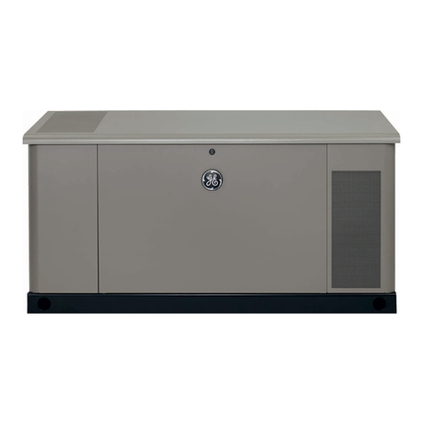
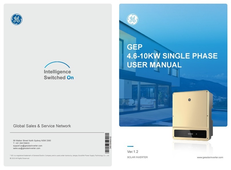
GE GEP3.5-1-10 User manual

www.gesolarinverter.com
V1.0
Grid-Tied PV Inverter

I
Copyright Statement
User Manual V1.0-2022-05-05
The information in this user manual is subject to change due to product updates or other
reasons. This guide cannot replace the product labels or the safety precautions in the user
manual unless otherwise specied. All descriptions here are for guidance only.
and other GE trademarks are trademarks of General Electric Company. All other
trademarks or registered trademarks mentioned in this manual are owned by General Electric
Company.
Trademarks
NOTICE

II
CONTENT User Manual V1.0-2022-05-05
CONTENT
1 About This Manual .................................................................1
1.1 Applicable Model..........................................................................................1
1.2 Target Audience............................................................................................1
1.3 Symbol Denition.........................................................................................1
1.4 Updates .........................................................................................................1
2 Safety Precaution...................................................................2
2.1 General Safety ..............................................................................................2
2.2 DC Side: .........................................................................................................2
2.3 AC Side...........................................................................................................2
2.4 Inverter Installation .....................................................................................3
2.5 Personal Requirements...............................................................................3
2.6 EU Declaration of Conformity.....................................................................4
3 Product Introduction.............................................................5
3.1 Application Scenarios ..................................................................................5
3.2 Circuit Diagram.............................................................................................5
3.3 Supported Grid Types..................................................................................5
3.4 Appearance...................................................................................................6
3.4.1 Appearance............................................................................................................6
3.4.3 Indicators ...............................................................................................................7
3.4.3 Nameplate .............................................................................................................8
4 Check and Storage .................................................................9
4.1 Check Before Receiving...............................................................................9
4.2 Deliverables ..................................................................................................9
4.3 Storage ........................................................................................................10
5 Installation ............................................................................11
5.1 Installation Requirements.........................................................................11
5.2 Inverter Installation ................................................................................14
5.2.1 Moving the Inverter............................................................................................14
5.2.2 Installing the Inverter.........................................................................................14
III
CONTENT
User Manual V1.0-2022-05-05
6 Electrical Connection...........................................................15
6.1 Safety Precaution .......................................................................................15
6.2 Connecting the PE Cable ...........................................................................16
6.3 Connecting the PV Input Cable ................................................................16
6.4 Connecting the AC Output Cable .............................................................19
6.5 Communication ..........................................................................................21
6.5.1 Communication Network Introduction............................................................21
6.5.1 Connecting the Communication Cable (optional)...........................................21
6.5.3 Installing the Communication Module (optional)...........................................26
7 Equipment Commissioning.................................................27
7.1 Check Before Power ON ............................................................................27
7.2 Power On.....................................................................................................27
8 System Commissioning .......................................................28
8.1 Indicators and Buttons..............................................................................28
8.2 Setting Inverter Parameters via LCD ......................................................28
8.2.2 Inverter Parameter Introduction ......................................................................36
8.3 Setting Inverter Parameters via SolarGo App ........................................37
8.4 Monitoring via Power Sight......................................................................37
9 Maintenance.........................................................................38
9.1 Power O the Inverter...............................................................................38
9.2 Removing the Inverter...............................................................................38
9.3 Disposing of the Inverter ..........................................................................38
9.4 Troubleshooting .........................................................................................38
9.5 Routine Maintenance.................................................................................41
10 Technical Parameters ........................................................42

Disclaimer
1
User Manual V1.0-2022-05-05
1 About This Manual
1.1 Applicable Model
1.2 Target Audience
This manual describes the product information, installation, electrical connection, commissioning,
troubleshooting, and maintenance. Read through this manual before installing and operating the
product. All the installers and users have to be familiar with the product features, functions, and
safety precautions. This manual is subject to update without notice. For more product details and
latest documents, visit https://www.gesolarinverter.com.
This manual applies to trained and knowledgeable technical professionals. The technical
personnel has to be familiar with the product, local standards, and electric systems.
This manual applies to the listed inverters below (GEP or Inverter for short):
Model Nominal Output Power Nominal Output Voltage
GEP3.5-1-10 3.5kW
220/230V
GEP3.6-1-10 3.6kW
GEP4.2-1-10 4.2kW
GEP4.6-1-10 4.6kW
GEP5.0-1-10 5kW
1.3 Symbol Denition
Dierent levels of warning messages in this manual are dened as follows:
DANGER
Indicates a high-level hazard that, if not avoided, will result in death or serious injury.
WARNING
Indicates a medium-level hazard that, if not avoided, could result in death or serious injury.
CAUTION
Indicates a low-level hazard that, if not avoided, could result in minor or moderate injury.
NOTICE
Highlight and supplement the texts. Or some skills and methods to solve product-related
problems to save time.
1.4 Updates
The latest document contains all the updates made in earlier issues.
V1.0 2022-05-05
• First Issue

Safety Precaution
2
User Manual V1.0-2022-05-05
2 Safety Precaution
2.1 General Safety
2.3 AC Side
Notice
• The information in this user manual is subject to change due to product updates or other
reasons. This guide cannot replace the product labels or the safety precautions in the user
manual unless otherwise specied. All descriptions here are for guidance only.
• Before installations, read through the quick installation guide. For additional information,
please see the user manual.
• All operations should be performed by trained and knowledgeable technicians who are
familiar with local standards and safety regulations.
• Use insulating tools and wear personal protective equipment when operating the
equipment to ensure personal safety. Wear anti-static gloves, cloths, and wrist strips when
touching electron devices to protect the inverter from damage.
• Strictly follow the installation, operation, and conguration instructions in this manual. The
manufacturer shall not be liable for equipment damage or personal injury if you do not
follow the instructions. For more warranty details, please visit https://www.gesolarinverter.
com/warranty.html.
Notice
The inverters are designed and tested strictly complies with related safety rules. Read and
follow all the safety instructions and cautions before any operations. Improper operation might
cause personal injury or property damage as the inverters are electrical equipment.
DANGER
Connect the DC cables using the delivered PV connectors. The manufacturer shall not be liable
for the equipment damage if other connectors or terminals are used.
WARNING
• Ensure the component frames and the bracket system are securely grounded.
• Ensure the DC cables are connected tightly, securely and correctly.
• Measure the DC cable using the multimeter to avoid reverse polarity connection. Also, the
voltage should be under the permissible range.
WARNING
• The voltage and frequency at the connection point meet the inverter grid connection
requirements
• Additional protective devices like circuit breakers or fuses are recommended on the AC
side. Specication of the protective device should be at least 1.25 times the rated AC output
rated current.
• You are recommended to use copper cables as AC output cables. Contact the manufacturer
if you want to use other cables.
2.2 DC Side:

Safety Precaution
3
User Manual V1.0-2022-05-05
2.4 Inverter Installation
DANGER High voltage hazard.
Disconnect all incoming power
and turn o the product before
working on it.
Delayed discharge. Wait
5 minutes after power o
until the components are
completely discharged.
Read through the user manual
before working on this device.
Potential risks exist. Wear
proper PPE before any
operations.
High-temperature hazard. Do
not touch the product under
operation to avoid being burnt.
Grounding point.
CE Mark Do not dispose of the inverter
as household waste. Discard
the product in compliance with
local laws and regulations,
or send it back to the
manufacturer.
DANGER
• Do not apply mechanical load to the terminals, otherwise the terminals can be damaged.
• All labels and warning marks should be visible after the installation. Do not scrawl,
damage, or cover any label on the device.
• Inverters should not be installed in multiple phase combination.
• Install the inverter away from high magnetic eld to avoid electromagnetic interference.
If there is any radio or wireless communication equipment below 30MHz near the inverter,
you have to:
• Install the inverter at least 30m far away from the wireless equipment.
• Add a low pass EMI lter or a multi winding ferrite core to the DC input cable or AC
output cable of the inverter.
• Warning labels on the inverter are as follows.
2.5 Personal Requirements
NOTICE
• Personnel who install or maintain the equipment must be strictly trained, learn about
safety precautions and correct operations.
• Only qualied professionals or trained personnel are allowed to install, operate, maintain,
and replace the equipment or parts.

Safety Precaution
4
User Manual V1.0-2022-05-05
2.6 EU Declaration of Conformity
General Electric Company hereby declares that the inverter with wireless communication
modules sold in the European market meets the requirements of the following directives:
• Radio Equipment Directive 2014/53/EU (RED)
• Restrictions of Hazardous Substances Directive 2011/65/EU and (EU) 2015/863 (RoHS)
• Waste Electrical and Electronic Equipment 2012/19/EU
• Registration, Evaluation, Authorization and Restriction of Chemicals (EC) No 1907/2006
(REACH)
General Electric Company hereby declares that the inverter without wireless communication
modules sold in the European market meets the requirements of the following directives:
• Electromagnetic compatibility Directive 2014/30/EU (EMC)
• Electrical Apparatus Low Voltage Directive 2014/35/EU (LVD)
• Restrictions of Hazardous Substances Directive 2011/65/EU and (EU) 2015/863 (RoHS)
• Waste Electrical and Electronic Equipment 2012/19/EU
• Registration, Evaluation, Authorization and Restriction of Chemicals (EC) No 1907/2006 (REACH)
You can download the EU Declaration of Conformity on https://www.gesolarinverter.com.

Product Introduction
5
User Manual V1.0-2022-05-05
3 Product Introduction
3.1 Application Scenarios
The GEP inverter is a single-phase PV string grid-tied inverter. The inverter converts the DC
power generated by the PV module into AC power and feeds it into the utility grid. The intended
use of the inverter is as follows:
PV String Inverter
Circuit
Breaker
Circuit Breaker
(optional)
Utility
Grid
3.2 Circuit Diagram
3.3 Supported Grid Types
For the grid type with neutral wire, the N to ground voltage must be less than 10V.
PV1+
PV1--
PV2+
PV2-
L
N
PE
MPPT1
MPPT2
DC Switch
EMI
Filter
EMI
Filter
EMI
Filter
DC SPD AC SPD
DC/AC
Inverter
Circuit
LC
Filter
Output
Disconnecting
Relay
Inverter Inverter Inverter Inverter

Product Introduction
6
User Manual V1.0-2022-05-05
3.4 Appearance
3.4.1 Appearance
No. Parts Description
1 DC Switch Start or stop DC input.
2PV Input Terminal Used to connect the PV module DC input cables.
3Communication Module Port Connect WiFi, LAN, WiFi/LAN communication
module.
4DRED/Remote Shutdown
Communication Cable Port
Used to connect the DRED or remote shutdown
communication cable.
5AC Output Terminal Used to connect the AC output cable, which connects
the inverter and the utility grid.
6Ventilation Valve -
7CT/RS485 Communication
Cable Port
Used to connect the CT or RS485 communication
cable.

Product Introduction
7
User Manual V1.0-2022-05-05
Indicator Status Description
ON = EQUIPMENT POWER ON
OFF = EQUIPMENT POWER OFF
ON = THE INVERTER IS FEEDING POWER
OFF = THE INVERTER IS NOT FEEDING POWER
SINGLE SLOW FLASH = SELF CHECK BEFORE CONNECTING TO
THE GRID
SINGLE FLASH = CONNECTING TO THE GRID
ON = WIRELESS IS CONNECTED/ACTIVE
BLINK 2 = WIRELESS ROUTER NOT CONNECTED
BLINK 4 = WIRELESS SERVER PROBLEM
BLINK = RS485 IS CONNECTED
ON = A FAULT HAS OCCURRED
OFF = NO FAULT
3.4.3 Indicators
Power
Operating
SEMS
Faulty
No. Parts Description
8PE Terminal Used to connect the PE cable.
9Indicator Indicates working state of the inverter.
10 LCD Used to check the parameters of the inverter.
11 Button Used to select menus displayed on the screen.
12 Mounting Plate Used to install the inverter.
13 Heat sink Used to cool the inverter.

Product Introduction
8
User Manual V1.0-2022-05-05
3.4.3 Nameplate
The nameplate is for reference only.
GE trademark, product type, and product model
Technical parameters
Safety symbols and certication marks
Contact information and serial number
S/N
********************************** Co.,Ltd.
E-mail: **********@****.com
***-*****-**
S/N:
* * * * *

Check and Storage
9
User Manual V1.0-2022-05-05
4 Check and Storage
4.1 Check Before Receiving
4.2 Deliverables
Check the following items before receiving the product.
1. Check the outer packing box for damage, such as holes, cracks, deformation, and other
signs of equipment damage. Do not unpack the package and contact the supplier as soon as
possible if any damage is found.
2. Check the inverter model. If the inverter model is not what you requested, do not unpack the
product and contact the supplier.
3. Check the deliverables for correct model, complete contents, and intact appearance. Contact
the supplier as soon as possible if any damage is found.
Notice
• The number of PV connectors and the PV terminals in the inverter is the same.
• The type and number of the communication connector are decided by the selected
• communication method.
• Communication module types: WiFi/LAN, WiFi, LAN etc. The actual module delivered
depends on the communication method of the selected inverter.
• The number of pin terminals are various depending on dierent inverters. The actual
accessories may dier.
Inverter *1 Mounting plate *1 Documents *1
COM module *N
Expansion bolt *6 PV connector *N
AC connector *1
DRED/Remote
Shutdown
connector*1
Grounding
screw *1 OT terminal *1
CT/RS485
connector *1 PIN Terminal *N
or

Check and Storage
10
User Manual V1.0-2022-05-05
4.3 Storage
If the equipment is not to be installed or used immediately, please ensure that the storage
environment meets the following requirements:
1. Do not unpack the outer package or throw the desiccant away.
2. Store the equipment in a clean place. Make sure the temperature and humidity are
appropriate and no condensation.
3. The height and direction of the stacking inverters should follow the instructions on the
packing box.
4. The inverters must be stacked with caution to prevent them from falling.
5. If the inverter has been long term stored, it should be checked by professionals before being
put into use.

Installation
11
User Manual V1.0-2022-05-05
5 Installation
5.1 Installation Requirements
1. Do not install the equipment in a place near ammable, explosive, or corrosive materials.
2. Install the equipment on a surface that is solid enough to bear the inverter weight.
3. Install the equipment in a well-ventilated place to ensure good dissipation. Also, the
installation space should be large enough for operations.
4. The equipment with a high ingress protection rating can be installed indoors or outdoors.
The temperature and humidity at the installation site should be within the appropriate range.
5. Install the equipment in a sheltered place to avoid direct sunlight, rain, and snow. Build a
sunshade if it is needed.
6. Do not install the equipment in a place that is easy to touch, especially within children’s
reach. High temperature exists when the equipment is working. Do not touch the surface to
avoid burning.
7. Install the equipment at a height that is convenient for operation and maintenance, electrical
connections, and checking indicators and labels.
8. Install the inverter away from high magnetic eld to avoid electromagnetic interference.If
there is any radio or wireless communication equipment below 30MHz near the inverter, you
have to:
• Install the inverter at least 30m far away from the wireless equipment.
• Add a low pass EMI lter or a multi winding ferrite core to the DC input cable or AC output
cable of the inverter.
Installation Environment Requirements
Children no touch

Installation
12
User Manual V1.0-2022-05-05
Installation Angle Requirements
• Install the inverter vertically or at a maximum back tilt of 15 degrees.
• Do not install the inverter upside down, forward tilt, back forward tilt, or horizontally.
Mounting Support Requirements
• The mounting support shall be nonammable and reproof.
• Make sure that the support surface is solid enough to bear the product weight load.
• Do not install the product on the support with poor sound insulation to avoid the noise
generated by the working product, which may annoy the residents nearby.

Installation
13
User Manual V1.0-2022-05-05
The following tools are recommended when installing the equipment. Use other auxiliary tools
on site if necessary.
Installation Tool Requirements
Goggles Safety shoes Safety gloves Dust mask
Diagonal pliers
Marker Level Heat shrink
tube
Rubber
hammer
DC wiring
wrench
Vacuum
cleaner
Torque wrench
Cable tieMultimeter
Wire stripper Hammer drill Heat gun
DC terminal
crimping tool

Installation
14
User Manual V1.0-2022-05-05
5.2 Inverter Installation
5.2.2 Installing the Inverter
5.2.1 Moving the Inverter
CAUTION
Move the inverter to the site before installation. Follow the instructions below to avoid
personal injury or equipment damage.
1. Consider the weight of the equipment before moving it. Assign enough personnel to move
the equipment to avoid personal injury.
2. Wear safety gloves to avoid personal injury.
3. Keep balance to avoid falling down when moving the equipment.
NOTICE
• Avoid the water pipes and cables buried in the wall when drilling holes.
• Wear goggles and a dust mask to prevent the dust from being inhaled or contacting eyes
when drilling holes.
• The DC switch lock is prepared by the customer.
Step 1 Put the mounting plate on the wall or the support horizontally and mark positions for
drilling holes.
Step 2 Drill holes to a depth of 80mm using the hammer drill. The diameter of the drill bit
should be 10mm.
Step 3 Secure the mounting plate using the expansion bolts.
Step 4 (Only for Australia.) Install the DC switch lock.
Step 5 Install the inverter on the mounting plate.
Step 6 Install the anti-theft lock.

Installation
15
User Manual V1.0-2022-05-05
6 Electrical Connection
6.1 Safety Precaution
NOTICE
• Wear personal protective equipment like safety shoes, safety gloves, and insulating gloves
during electrical connections.
• All electrical connections should be performed by qualied professionals.
• Cable colors in this document are for reference only. The cable specications shall meet local
laws and regulations.
DANGER
• Disconnect the DC switch and the AC output switch of the inverter to power o the inverter
before any electrical connections. Do not work with power on. Otherwise, an electric shock
may occur.
• Perform electrical connections in compliance with local laws and regulations. Including
operations, cables, and component specications.
• If the cable bears too much tension, the connection may be poor. Reserve a certain length of
the cable before connecting it to the inverter cable port.
For Australia only.

Electrical Connection
16
User Manual V1.0-2022-05-05
WARNING
• The PE cable connected to the enclosure of the inverter cannot replace the PE cable
connected to the AC output port. Make sure that both of the two PE cables are securely
connected.
• Make sure that all the grounding points on the enclosures are equipotential connected
when there are multiple inverters.
• To improve the corrosion resistance of the terminal, you are recommended to apply silica
gel or paint on the ground terminal after installing the PE cable.
• The PE cable is prepared by the customer. Recommended specications:
• Type: single-core outdoor copper cable
• Conductor cross-sectional area: 4mm2
6.2 Connecting the PE Cable
6.3 Connecting the PV Input Cable
DANGER
Conrm the following information before connecting the PV string to the inverter. Otherwise,
the inverter may be damaged permanently or even cause re and cause personal and property
losses.
1. Make sure that the max short circuit current and the max input voltage per MPPT are within
the permissible range.
2. Make sure that the positive pole of the PV string connects to the PV+ of the inverter. And the
negative pole of the PV string connects to the PV- of the inverter.
WARNING
• Connect the DC cables using the delivered PV connectors. The manufacturer shall not be
liable for the damage if other connectors are used.
• The PV strings cannot be grounded. Ensure the minimum isolation resistance of the
PV string to the ground meets the minimum isolation resistance requirements before
connecting the PV string to the inverter.
• The DC input cable is prepared by the customer. Recommended specications:
• Type: the outdoor photovoltaic cable that meets the maximum input voltage of the
inverter.
• Conductor cross-sectional area: 2.5~4mm2(Devalan) or 4~6mm2 (MC4).(MC4)
Copper,
This manual suits for next models
4
Table of contents
Other GE Inverter manuals

GE
GE HOME NERATOR 10000 WATT Installation and operation manual

GE
GE 20 kW Home Installation and operation manual

GE
GE 076004-0 Setup guide

GE
GE HGS Installation and operation manual

GE
GE VAT300 Series User manual

GE
GE HOME NERATOR 7000 WATT Installation and operation manual

GE
GE 60000 Series Installation and operation manual

GE
GE 40350 Installation and operation manual

GE
GE HOME NERATOR SYSTEM 12000 WATT Installation and operation manual

GE
GE GEP User manual