MultiNet Page 3 of 15
GE Digital Energy http://www.GEmultilin.com
effect is a reduction in cable length and bit rate. Termination capacitor values are
dependent on various factors, including the number of Unit Loads, network data rate,
and cable length. The termination capacitor value provided in the instruction manual
should be taken as a guideline only. In order to determine the optimum capacitor value
factors, such as number of devices connected on the network, network speed, physical
media, and network cable length, should be considered.
10BASE-F FIBER OPTIC PORT
The fiber optic communications port allows for fast and efficient communications with Modbus TCP/IP
at 10 Mbps. Fiber optic transmissions provide an ideal solution for areas where RS485
communications or Ethernet via a twisted pair have traditionally caused problems. Fiber is immune to
electrical interference and provides complete isolation.
Optical fibers may be connected to the MultiNet supporting a wavelength of 820 nm in multimode.
Optical fiber is only available with the MultiNet-FE option (see the Order Code for details). The
MultiNet-FE has a 10BaseF transmitter/receiver for optical fiber communications and supports optical
fiber sizes of 50/125 µm, 62.5/125 µm, and 100/140 µm. The fiber optic port is designed such that the
response times will not vary for any core 100 µm or less in diameter. For optical power budgeting,
splices are required every 1 km for the transmitter/receiver pair (the ST type connector contributes for
a connector loss of 0.2 dB). When splicing optical fibers, the diameter and numerical aperture of each
fiber must be the same. Only a quarter turn of the coupling is required to engage or disengage the ST
type connector.
The 10BaseT Ethernet port and the 10BaseF Fiber port are internally linked and should not be used
together.
CAUTION
Ensure the dust covers are installed when the fiber is not In use. Dirty or
scratched connectors can lead to high losses on a fiber link.
CAUTION
Observing any fiber transmitter output may cause injury to the eye!
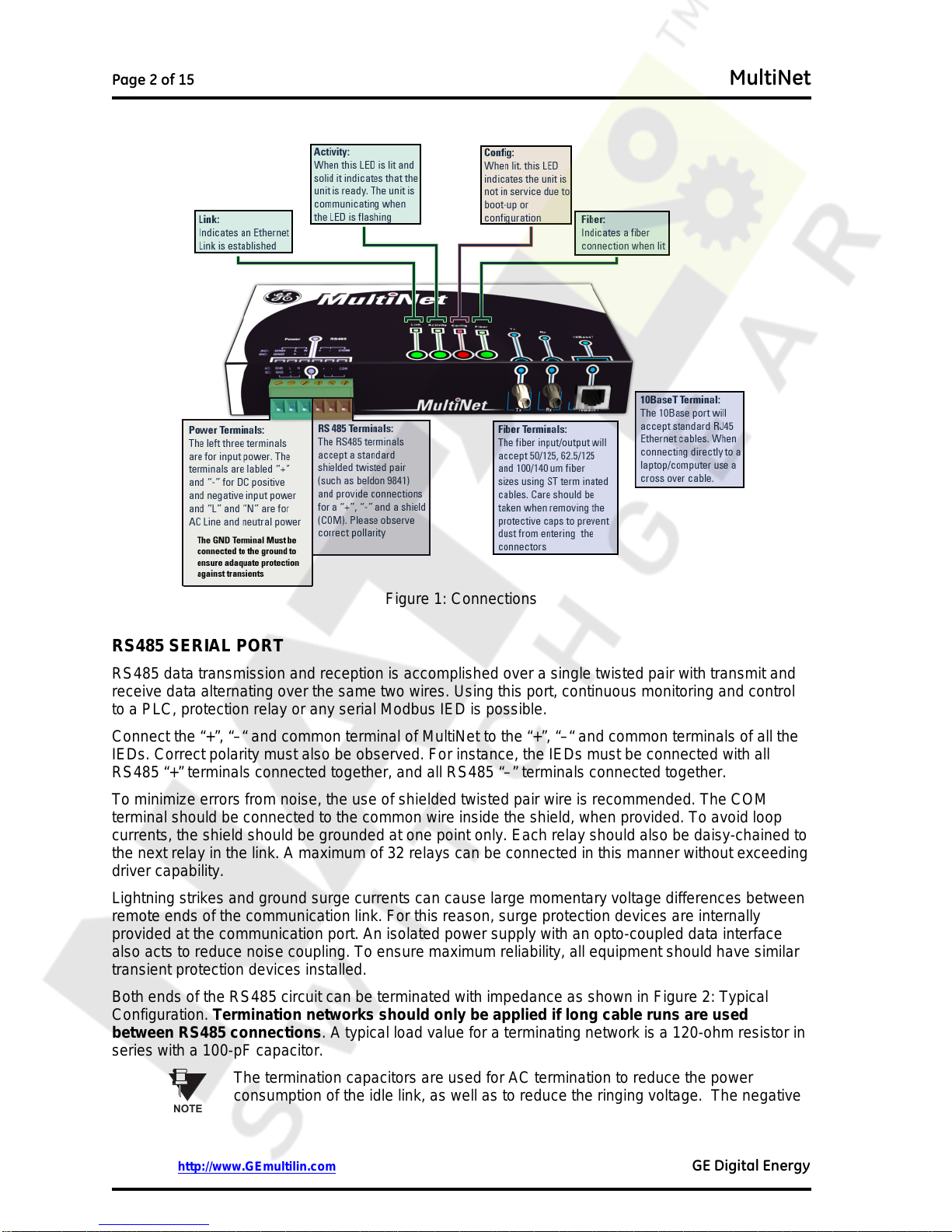
INPUT POWER TERMINALS
The input power terminals are located on the left side of the green terminal block. MultiNet may be
connected to either 90 to 265 V AC at 50/60 Hz or 90 to 300 V DC supply power. The terminals are
labeled "+" and "–" for DC positive and negative input power and "L" and "N" are for AC line and
neutral input power. The GND terminal must be connected to ground to ensure adequate protection
against transients.
CAUTION
Control power supplied to the MultiNet must be connected to the matching power
supply range. If the voltage is applied to the wrong terminals, damage may occur!
MOUNTING
MultiNet is DIN rail mountable and ships with two DIN rail clips attached on the rear of the unit. The
DIN rail clips can attach the unit onto a standard 35 mm DIN rail. Place the top hooks of the clip
against the DIN rail and apply a downward force until an audible click is heard. In order to remove the
unit, place a standard slotted screwdriver between the unit and the DIN rail and apply an upward
force.
Each clip is held onto the unit using a standard 4-40 Phillips head screw. If the DIN rail option is not
used, remove the DIN rail clips by unscrewing the six screws. Once the clips have been removed re-