GE Video Converter RF Modulator with S-Video User manual

Video Converter
RF Modulator with S-Video
Conversor de video
Modulador de RF con S-video
Instrucciones
Instrucciones
en español
incluidas

2
NOTE TO CATV SYSTEM INSTALLER:
This reminder is provided to call the CATV system installer’s atten-
tion to Article 820-40 of the NEC that provides guidelines for proper
grounding and, in particular, specifi es that the cable ground shall be
connected to the grounding system of the building, as close to the
point of cable entry as practical.
WARNING: To prevent fi re or shock hazard, do not expose this product
to rain or moisture. This unit for indoor use only.
CAUTION
RISK OF ELECTRIC SHOCK
DO NOT OPEN
CAUTION: TO REDUCE THE RISK OF ELECTRIC SHOCK,
DO NOT REMOVE COVER OR BACK. NO USER-SERVICEABLE
PARTS INSIDE. REFER SERVICING TO QUALIFIED PERSONNEL.
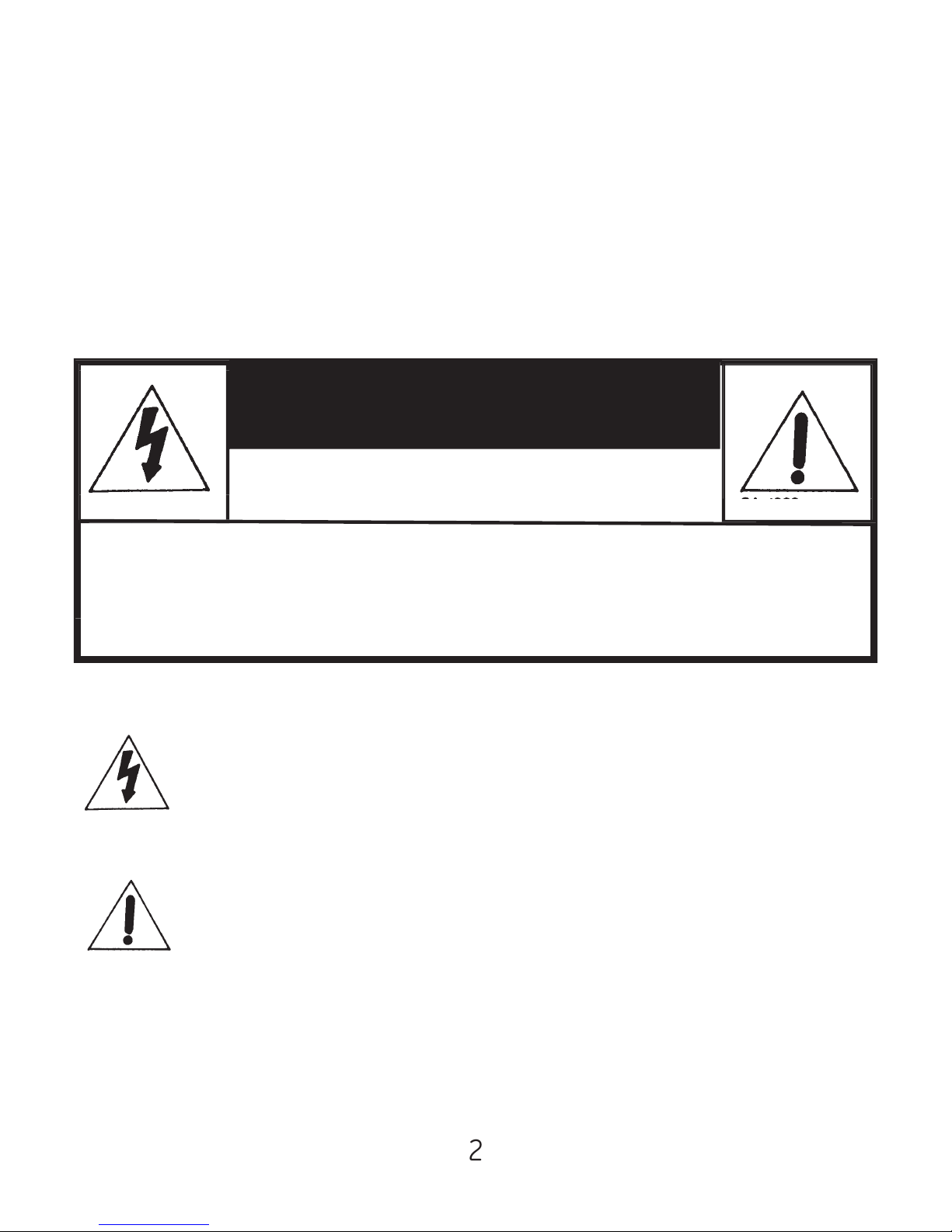
The lightning fl ash with arrowhead symbol, within an
equilateral triangle, is intended to alert the user to the
presence of uninsulated “dangerous voltage” within the
product’s enclosure that may be of suffi cient magnitude to
constitute a risk of electric shock to persons.
The exclamation point with an equilateral triangle is
intended to alert the user to the presence of important
operating and maintenance (servicing) instructions in the
literature accompanying the appliance.
Notice: The changes or modifi cations not expressly approved by the
party responsible of compliance could void the user’s authority to
operate the equipment.
CAUTION: TO REDUCE THE RISK OF ELECTRIC SHOCK,
DO NOT REMOVE COVER OR BACK. NO USER-SERVICEABLE
PARTS INSIDE. REFER SERVICING TO QUALIFIED PERSONNEL.

3
INTRODUCTION
Your Video Converter (RF modulator) is designed to convert the
separate audio and video signals (from a DVD, video camera, or video
game, for example) into VHF TV signals that you can view on a TV set
equipped with only a 75 Ohm (F-type) input.
THE FCC WANTS YOU TO KNOW
This device complies with Part 15 of FCC Rules. Operation is subject to
the following two conditions: (1) this device may not cause harm-
ful interference, and (2) this device must accept any interference
received, including interference that may cause undesired operation.
Your modulator might cause TV or radio interference even when
operating properly. To determine whether your modulator is caus-
ing the interference, turn it off. If the interference goes away, your
modulator is causing it.
Try to eliminate the interference by:
• Moving your RF Modulator away from the receiver
• Connecting your RF Modulator to an outlet on a different electrical
circuit from the receiver
• Contacting your local store for help
If you cannot eliminate the interference, the FCC requires you stop
using your RF Modulator. Changes or modifi cations not expressly ap-
proved by the party responsible for compliance could void the user’s
FCC authorization to operate this equipment.

4
CABLES REQUIRED TO CONNECT YOUR NEW RF MODULATOR
The following items (not supplied) are required to connect your RF
Modulator to a video input source and your TV.
• One audio/video cable with red, white, and yellow RCA connectors
(AV23216), or
• One audio cable with red and black RCA connectors (AV22607)
• One video cable with RCA connector (AV23319)
• One s-video cable (AV23244)
• Two 75 ohm coax cables with “F” type connectors (AV23217)
Note: The audio signal will be modulated to mono, whether the video
source is stereo or monaural.
Note: Enclosed 4 rubber feet can be attached to the product if you
want to use this RF modulator in a horizontal position.
Note to the CATV System Installer:
This reminder is provided to call the CATV system installer’s attention
to article 820-22 of the NEC which provides guidelines for proper
grounding and, in particular, specifi es the cable ground shall be con-
nected to the grounding system of the building, as close to the point
of cable entry as practical.

5
CONNECTING YOUR RF MODULATOR
1. Using the audio/video cable, connect
the red and white RCA connectors to
the audio out from the VCR or DVD
matching red to red and white to
white.
2. Connect the yellow RCA connector to
the yellow video out from the VCR or
DVD.
3. Connect the other end of the au-
dio/video cable to the input of the RF
modulator, matching the red to red,
white to white and yellow to yellow.
4. Using one of the 75 ohm coax cables,
connect one end of the cable to the F
connector labeled out to TV. Connect
the other end of the 75 ohm coax
cable to the Ant In on the back of the
TV.
5. Plug in the RF modulator to a 120V
AC power outlet.

6
CONNECTING YOUR RF MODULATOR
USING THE S-VIDEO CONNECTOR
1. Using the audio cable connect the
red and white RCA connectors to the
audio out on the VCR or DVD, match-
ing red to red and white to white.
2. Using the s-video cable, connect
one end of the s-video cable to the
s-video port on the back of the VCR
or DVD.
3. Take the other end of the audio cable
and connect it to the audio In of the
RF modulator, matching red to red,
and black to white.
4. Take the other end of the s-video
cable and connect the s-video plug
into the s-video port on t he RF
modulator.
5. Using one of the 75 ohm coax cables,
connect one end of the cable to the F
connector labeled To TV. Connect the
other end of the 75 ohm coax cable
to the Ant In on the back of the TV.
6. Plug the RF modulator into a 120V AC
power outlet.

7
CONNECTING CATV, EXTERNAL
ANTENNA OR SATELLITE
CATV (without box, direct from CATV
wallplate:
1. Using the other 75 coax cable, con-
nect one end to the CATV wall plate.
2. Connect the other end of the cable
to the Ant In on the RF modulator.
3. Plug the RF Modulator’s power cord
into a standard AC outlet.
CATV without box or satellite:
1. Using the 75 ohm cable, connect
one end of the cable to the cable box
or satellite box to the F connector
labeled Out to TV or Out.
2. Connect the other end of the coax
cable to the Ant In on the RF modula-
tor.
3. Plug the RF Modulator’s power cord
into a standard AC outlet.

8
If your video source is monaural:
1. Plug the connectors on one end of an
A/V cable into the video and audio in-
put jacks on the RF Modulator (using
the AUDIO L jack).
2. Plug the cable’s other ends into the
video and audio jacks on the video
source.
3. Connect the 75 ohm coaxial cables
to the RF Modulator following these
guidelines.
4. Plug the RF Modulator’s power cord
into a standard AC outlet.
If your TV is already connected to
another VHF input source (such as
cable, an antenna, or a VCR, for
example):
1. Disconnect the VHF input source’s
75 ohm cable from the TV’s 75 ohm
VHF/UHF terminal, and reconnect it
to the RF Modulator’s Ant In terminal.
2. Connect a 75 ohm coaxial cable
between the To TV terminal on the RF
Modulator and the 75 ohm VHF/UHF
terminal on your TV.
3. Plug the RF Modulator’s power cord
into a standard AC outlet.

9
If your TV is not already connected to
another VHF source:
1. Connect a 75 ohm coaxial cable be-
tween the To TV terminal on the RF
modulator and the 75 ohm VHF/UHF
terminal on your TV.
2. Plug the RF Modulator’s power cord
into a standard AC outlet.
Note:
If your TV has only 300 ohm VHF
screw terminals, use a 75 ohm to 300
ohm matching transformer to complete
the connection.

10
OPERATION
1. Turn on the TV and set it to either
channel 3 or 4, whichever is not used
for regular broadcasts in your area.
2. Set the RF Modulator’s CHANNEL 3/4
switch to the same channel you set
the TV (3 or 4).

11
CARE
To enjoy your RF modulator for a long time:
• Keep the modulator dry. If it gets wet, wipe it dry immediately.
• Use and store the modulator only in normal temperature
environments.
• Handle the modulator gentle and carefully. Don’t drop it.
• Keep the modulator away from dust and dirt.
• Wipe the modulator with a damp cloth occasionally to keep it
looking new.
Modifying or tampering with the modulator’s internal components
can cause a malfunction and invalidate its warranty and void your
FCC authorization to operate it. If your modulator is not performing
as it should, take it to your local store for assistance.
SPECIFICATIONS
Video Carrier Output Level 69dB_V
RF Output Channels 3 or 4
RF Output Impedance 75 ohms
Audio Input Impedance 13_3K ohms
TV to ANT Insertion Loss 50 - 806 MHz -2dB
Dimensions 114/16x32/
16x513/16 inches
Weight 14.5 oz.
Specifi cations are typical; individual units might vary. Specifi cations
are subject to change and improvement without notice.

12
FCC Compliance Statement
This equipment has been tested and found to comply with the limits
for a Class B digital device, pursuant to part 15 of the FCC Rules.
These limits are designed to provide reasonable protection against
harmful interference in a residential installation. This equipment
generates, uses and can radiate radio frequency energy and, if not
installed or used in accordance with the instructions, may cause
harmful interference to radio communications. However, there is no
guarantee interference will not occur in television reception, which
can be determined by turning the equipment off and on, the user is
encouraged to try and correct the interference by one or more of the
following measures:
(1) Reorient or relocate the receiving antenna.
(2) Increase the separation between the equipment and the receiver.
(3) Connect the equipment into an outlet on a circuit different from
that to which the receiver is connected.
(4) Consult the dealer or an experienced radio/TV technician for help.
FCC Warning:
Changes or modifi cations not expressly approved by the party
responsible for compliance could void the user’s authority to operate
the equipment.

13
90 DAY LIMITED WARRANTY
Jasco Products Company warrants this product to be free from
manufacturing defects for a period of ninety days from the original
date of consumer purchase. This warranty is limited to the repair or
replacement of this product only and does not extend to consequen-
tial or incidental damage to other products that may be used with
this unit. This warranty is in lieu of all other warranties express or
implied. Some states do not allow limitations on how long an implied
warranty lasts or permit the exclusion or limitation of incidental or
consequential damages, so the above limitations may not apply to
you. This warranty gives you specifi c rights, and you may also have
other rights which vary from state to state. If unit should prove
defective within the warranty period, return prepaid with dated proof
of purchase to:
Jasco Products Company
311 N.W. 122nd
Oklahoma City, OK. 73114

14
NOTA PARA EL INSTALADOR DEL SISTEMA CATV:
Se provee este aviso para que el instalador del sistema CATV se fi je
en el articulo 820-40 de NEC, que provee guias para una conexión
a tierra apropiada y, en particular, especifi ca que el cable que va a
tierra debe ser conectado al sistem conectado a tierra del edifi cio,
tan cercano al punto de la entrada del cable como sea posible.
ADVERTENCIA: Para prevenir un incendio o choque eléctrico, no
exponga este producto a la lluvia o humedad. Esta unidad es para
uso en itneriores solamente.
PRECAUCION
RIESGO DE ELECTROCUCION NO ABRIR
PRECAUCION: PARA REDUCIR EL RIESGO DE ELECTROCUCION, NO
REMUEVA LA CUBIERTA O LA PARTE POSTERIOR. NO TIENE PARTES
QUE SE MANTENGAN POR EL USARIO. ELSERVICIO DEBE SER HECHO
POR PERSONAL CAPACITA DO.
El simbolo de relámpago dentro de un triángulo equilátero,
tiene la intención de alertar al usario de la presencia
de “voltaje peligroso” no aislado dentro del recinto del
producto, que puede tener la sufi ciente magnitud como
para electrocutar personas.
El signo de exclamación con un triángulo equilátero tiene
la intención de alertar al usario de la presencia de
importantes instrucciones de operación y mantenimiento
(servicio) en la literatura que acompaña el aparato elétrico.
Nota: Los cambios o modifi caciones no aprobados expresamente por
la parte responsable con el cumplimiento de las normas correspondi-
entes, puede invalidar la autoridad del usarion para operar el equipo.

15
INTRODUCCÓN
Su Modulador RF de Video está diseñado para convertir las señales
separadas de video y audio (por ejemplo, de una cámara de video,
computadora, videocasetera portátil o recibidor de satélite) en se-
ñales VHF TV que usted puede ver un una televisión.
LA FCC QUIERE INFORMARLE A USTED
Este aparato cumple con la Parte 15 de las Reglas de la FCC. La Este
aparato no puede causar interferencia dañina y (2) este aparato
debe aceptar cualquier interferencia recibida, incluendo interferencia
que pueda causar la operación no deseada.
Su modulado rpuede causar interferencia con la televisión o el radio
aún cuando esté causando la interferencia, apáguelo. Si la itnerfer-
encia desaparece, la esá causando su modulador.
Trate de eliminar la interferrencia:
• Moviendo su Modulador RF lejos del recibidor
• Conectando su Modulador RF a un enchufe que se encuentre en un
circuito eléctrico diferente del recibidor
• Contactando a su tienda local para pedir ayuda.
Si o puede eliminar la interferencia, la FCC requiere que usted deje de
utilizar su Modulador RF. Los combios y modifi caciones no aprobados
expresamente por la parte responsable del cumplimiento con las
normas correspondientes, puede dinvalidar la autorizacíon de la FCC
al usuario para operar este equipo.

16
CABLES NECESARIOS PARA CONECTAR SU NUEVO MODULADOR DE RF
Los siguientes artívulos (no incluidos) son requeridos para conectar
su Modulador RF a una fuente de salida de video y a su televisión.
• Un cable de audio/video con conectores RCA rojo, blanco y amarillo
(AV23216) o
• Un cable de audio con conectores RCA rojo y negro (AV22607)
• Un cable de video con conector RCA (AV23319)
• Un cable de S-video (AV23244)
• Dos cables coaxiales de 75 ohmios con conectores tipo “F”
(AV23217)
Nota: La señal de audio será modulada en monoaural, ya sea que la
fuente de video sea estéreo o monoaural.
Nota: Les 4 pieds en caoutchouc ci-inclus peuvent être ajoutés pour
utiliser ce modulateur HF en position horizontale.
Nota para el Instalador del sistema CATV: Este aviso se provee para
que el instalador del sistema CATV se fi je en el articulo 820-22 de
NEC, que provee guías para una conexión a tierra apropiada y, en
particular, especifi ca que el cable que va a tierra debe ser conectado
al sistema conectado a tierra del edifi cio, tan cercano al punto de la
entrada del cable como sea posible.

17
CONEXIÓN DE SU MODULADOR DE RF
1. Mediante el cable de audio/video,
acople los conectores RCA rojo y
blanco a la salida de audio de la
videograbadora o DVD de manera
que coincidan rojo con rojo y
blanco con blanco.
2. Acople el conector RCA amarillo
a la salida amarilla de video de la
videograbadora o DVD.
3. Acople el otro extremo del cable
de audio/video a la entrada del
modulador de RF, de manera que
coincidan rojo con rojo, blanco con
blanco y amarillo con amarillo.
4. Mediante uno de los cables
coaxiales de 75 ohmios, acople un
extremo del cable al conector F
marcado “out to TV” (salida a TV).
Acople el otro extremo del cable
coaxial de 75 ohmios a “Ant In”
(entrada de antena) en la parte
posterior del televisor.
5. Enchufe el modulador de RF a una
toma eléctrica de corriente alterna
de 120V.

18
CONEXIÓN DE SU MODULADOR DE RF
CON CONECTOR DE S-VIDEO
1. Mediante el cable de audio, acople
los conectores RCA rojo y blanco a
la salida de audio de la videograba-
dora o DVD, de manera que coincida
rojo con rojo y blanco con blanco.
2. Mediante el cable de S-video, acople
un extremo del cable de S-video al
puerto de S-video en la parte poste-
rior de la videograbadora o DVD.
3. Tome el otro extremo del cable
de audio y conéctelo a audio in
(entrada de audio) del modulador de
RF, de manera que coincida rojo con
rojo y negro con blanco.
4. Tome el otro extremo del cable de
S-video y conecte al enchufe de
S-video al puerto de S-video del
modulador de RF.
5. Mediante uno de los cables coaxia-
les de 75 ohmios, acople un extremo
del cable al conector F marcado
“To TV” (al televisor). Acolpe el otro
extremo del cable coaxial de 75 oh-
mios a “Ant In” (entrada de antena)
en la parte posterior del televisor.
6. Enchufe el modulador de RF en una
toma eléctrica de corriente alterna
de 120V.

19
CONEXIÖN DE TV por CABLE, AN-
TENA EXTERIOR O TV por CABLE
SATÉLITAL sin caja, directamente al
punto de toma de TV por CABLE en
la pared
1. Mediante el otro cable coaxial de
75 ohmios, conecte un extremo al
punto de toma de TV por CABLE en
la pared.
2. Conecte el otro extremo del cable
a “Ant In” (entrada de antena) en el
modulador de RF.
3. Enchufe el cable de alimentación
eléctrica del modulador de RF a
una toma eléctrica estándar de
corriente alterna.
TV por CABLE sin caja ni satélite:
1. Mediante el cable de 75 ohmios,
conecte un extremo del cable al de-
codifi cador de TV cable o el recep-
tor de TV por satélite al conector F
marcado “Out to TV” o “Out” (salida
a TV).
2. Conecte el otro extremo del cable
coaxial a “Ant In” (entrada de an-
tena) en el modulador de RF.
3. Enchufe el cable de alimentación
eléctrica del modulador de RF en
una toma estándar de corriente
alterna.

20
Si fu fuente de video es monoaural,
enchufe los conectores en el extremo
de un cable de A/V en los receptácu-
los de entrada de video y audio en
el Moudlador RF (utilizando ya sea el
receptáculo AUDIO R oL). Enchufe los
otros extremos del cable a los recep-
táculos de video y audio de la fuente
de video. Conecte los cables coaxiales
de 75 ohm al Moulador RF de acuerdo
a la siguiente guia:
Si su televisión ya está conectada a
otra fuente de entrada VHF (como por
ejemplo, un cable, una anena o una
videocasetera), desconecte el cable de
la fuente de entrada VHF de 75 ohm
de la terminal VHF/UHF de 75 ohm de
la televisión y vuelva a conectario a
la terminal del Modulador RF Ant IN.
Después conecte el cable coaxial de
75 ohm entre la terminal To TV en el
Modulador RF y la terminal VHF/UHF
de 75 ohm en su televisión.
Table of contents
Languages:
Other GE Media Converter manuals