GE Multilin F485 User manual

F485
Communications Converter
Instruction Manual
F485 Communications Converter
Manual P/N: 1601-0073-A5
GE publication code: GEK-119569A
GE
Grid Solutions
*1601-0073-A5*
LISTED

Copyright © 2017 GE Multilin Inc. All rights reserved.
GE Multilin F485 Communications Converter Instruction Manual.
Digital Energy, Multilin, and GE Multilin are trademarks or registered trademarks of GE
Multilin Inc.
The contents of this manual are the property of GE Multilin Inc. This documentation is
furnished on license and may not be reproduced in whole or in part without the permission
of GE Multilin. The content of this manual is for informational use only and is subject to
change without notice.
Part number: 1601-0073-A5 (September 2017)
Revision history
Release Dates
Major Updates for A5
Major Updates for A4
Part No. Revision Release Date
1601-0073-A3 1.0x April 2003
1601-0073-A4 1.0x July 2013
1601-0073-A5 1.0x September 2017
Page Changes
Cover Manual revision from A4 to A5; Branding, format, and colors updated
to GE Grid Solutions; Bar code, 10 year warranty, UL logo added
Page 1 Warranty information updated
General Branding and colors throughout updated to GE Grid Solutions
Page Changes
Cover Manual revision from A3 to A4; Contact information updated
Page 1 Removed 220 VAC model from Features list, and some images
Page 8 Removed contact information (also on cover)

F485 COMMUNICATIONS CONVERTER – INSTRUCTION MANUAL 1
Introduction
Features
• Converts between RS232, RS485 or Fiber
• 1200 to 57600 baud rates
• Isolated RS485 interface
• 50/125µm, 62.5/125µm, and 100/140µm fiber sizes
• Front panel LEDs for power, RS232 Rx/Tx, and RS485 Rx/Tx
• Two possible mounting arrangements
• 120 V AC adapter included (ANOMA AEC-3590 or other listed direct plug-in Class 2
power supply rated maximum 9 V DC output).
• Additional power supply terminals supplied to accept isolated 9 V AC / 9 V DC
• Two interface cables provided (9 pin - 9 pin, 9-pin - 25 pin)
• Suitable for use with direct or modem communications.
• E83849 UL Listed for the USA and Canada
Contact information
For product support, contact the information and call center as follows:
GE Grid Solutions
650 Markland Street
Markham, Ontario
Canada L6C 0M1
Worldwide telephone: +1 905 927 7070
Europe/Middle East/Africa telephone: +34 94 485 88 54
North America toll-free: 1 800 547 8629
Fax: +1 905 927 5098
Website: http://www.gegridsolutions.com/multilin
Warranty
For products shipped as of 1 October 2013, GE warrants most of its GE manufactured
products for 10 years. For warranty details including any limitations and disclaimers, see
our Terms and Conditions at https://www.gegridsolutions.com/multilin/warranty.htm
For products shipped before 1 October 2013, the standard 24-month warranty applies.

2F485 COMMUNICATIONS CONVERTER – INSTRUCTION MANUAL
Typical Configurations
Figure 1: RS232 to RS485 connection
805753A3.CDR

F485 COMMUNICATIONS CONVERTER – INSTRUCTION MANUAL 3
Figure 2: RS232 to FIBER and FIBER to RS485
805754A3.CDR

4F485 COMMUNICATIONS CONVERTER – INSTRUCTION MANUAL
Order code
Connections
Figure 3: Connections
RS232
COMPUTER
FIBER OPTIC RS485 POWER POWER
9V
AC/DC
Tx Rx
COM
RS232
FIBER
POWER JACK
The RS232 connector on the F485 converter accepts a
standard 9-pin computer cable. See wiring diagram for pin
assignments.
The fiber input/output will accept 50/125, 62.5/125 and
100/140um fiber sizes using ST terminated cables. Care
should be taken when removing the protective caps to
prevent dust from entering the connectors.
Connect the supplied power
adapter to this input if power is not
supplied via the terminals. The
power adapter steps down
120/220 VAC to 9 VAC.
RS485
The RS485 terminals accept a standard shielded twisted
pair (such as Beldon 9841) and provide connections for a
"+", "-" and a shield. The RS485 terminals have a
terminating network installed internally and therefore, no
external terminating network is required. Observe correct
POWER TERMINALS
The power terminals accept either 9 VAC or 9 VDC to power
the F485 converter instead of using the power adapter. The
GND terminal must be connected to ground to ensure
adaquate protection against transients. Pin 4 is the main
transient ground for the converter.
GND
1 2 3 4 5 6
+ - + -
805700A1.CDR

F485 COMMUNICATIONS CONVERTER – INSTRUCTION MANUAL 5
Configuration
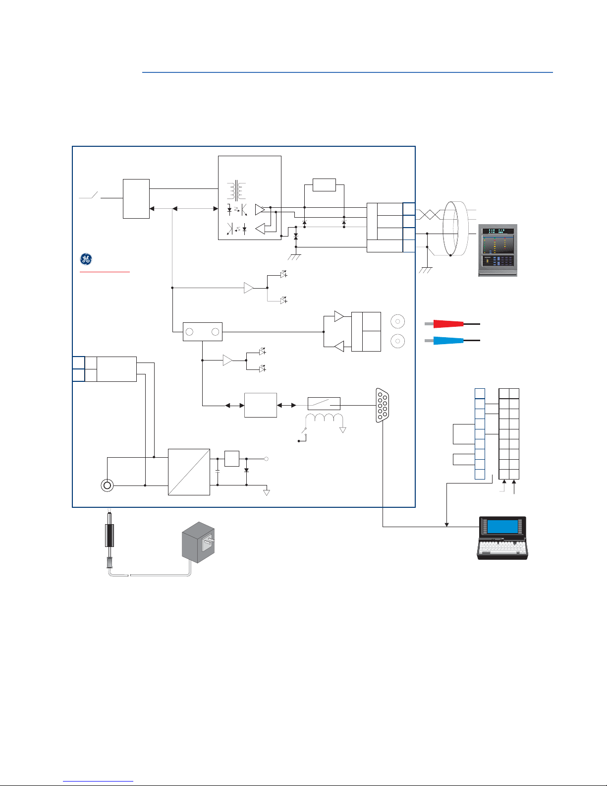
The converter box is configured via two internal dip switch banks which are accessible by
removing the converter box cover. Switches A1-A8 are used to set the baud rate for RS485
communications and determine whether the converter is DTE (RS232 direct) or DCE (RS232
modem). Switches B1-B6 are used to select the interface type. The designator for each
switch is clearly marked on the printed circuit board. The tables shown provide a
description of each switch within the switch banks.
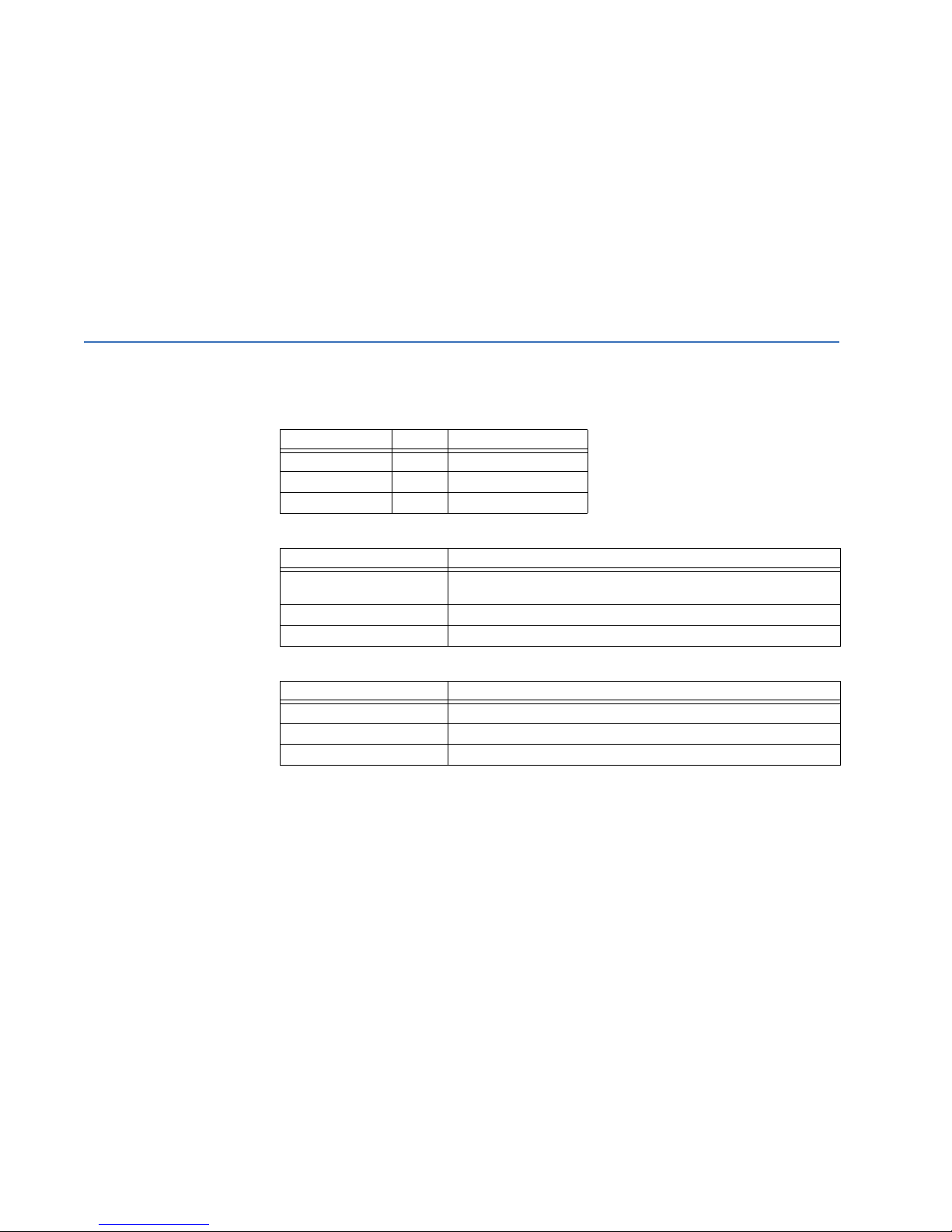
Table 1: Switch A (baud rates)
Table 2: Switch A (DTE/DCE)
Table 3: Switch B (configuration)
Baud rates
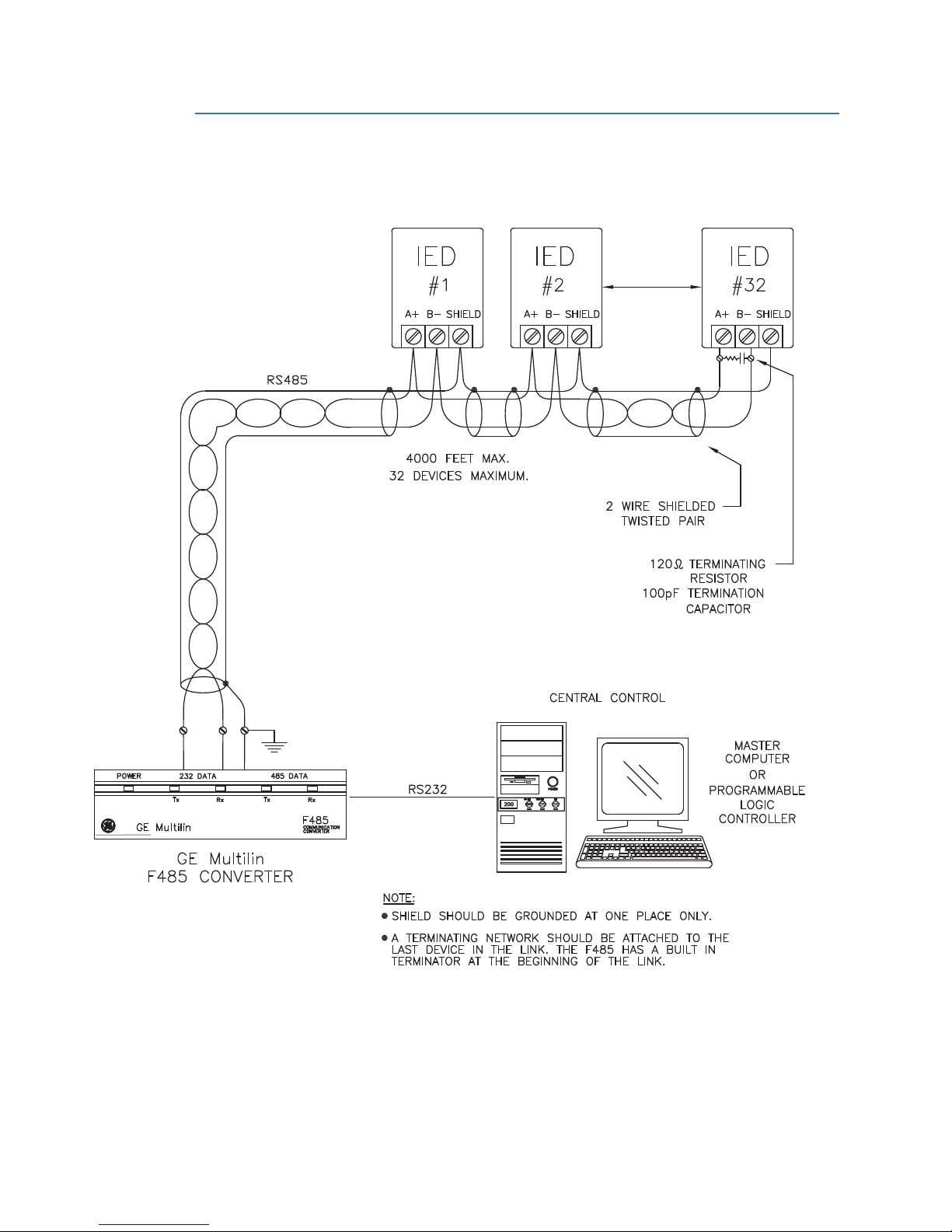
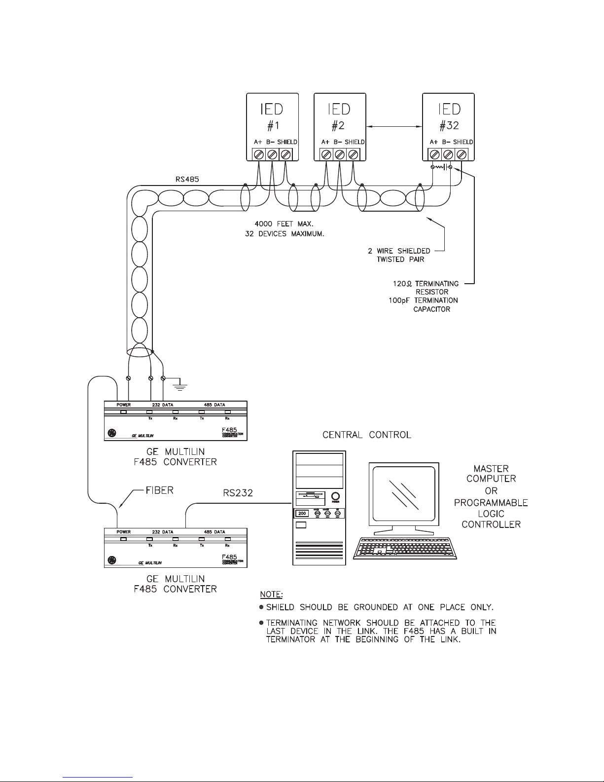
Two-wire RS485 is half duplex and requires a means for switching between a receive or
transmit state. The F485 converter uses the incoming data to control the direction and
therefore requires no control signals from the master device (RS232 or fiber) to switch from
transmit to receive mode after the last character has been transmitted. The baud rate
switches control the length of time that the RS485 transmitter will remain in the transmit
direction after the last character has been transmitted. The length of time is fixed at 3.5
character times at the selected baud rate making it suitable for use with Modbus® RTU
protocol. When converting RS232 to FIBER, these switches (A1-7) have no effect.
BAUD A1 A2 A3 A4 A5 A6 A7
1200 ON OFF OFF OFF OFF OFF OFF
2400 OFF ON OFF OFF OFF OFF OFF
4800 OFF OFF ON OFF OFF OFF OFF
9600 OFF OFF OFF ON OFF OFF OFF
19200 OFF OFF OFF OFF ON OFF OFF
38400 OFF OFF OFF OFF OFF ON OFF
57600 OFF OFF OFF OFF OFF OFF ON
MODE A8
DTE OFF
DCE ON
CONFIGURATIONB1B2B3B4B5B6
RS232 TO RS485 OFF ON OFF ON OFF OFF
RS232 TO FIBER OFF OFF OFF OFF ON ON
RS485 TO FIBER ON OFF ON OFF OFF OFF

6F485 COMMUNICATIONS CONVERTER – INSTRUCTION MANUAL
DTE/DCE control
The DTE/DCE setting reverses the transmit/receive data lines on the RS232 side. For
communications between a computer and a slave device, DTE (direct) should be selected.
When connecting the F485 converter to a modem or other data communications
equipment, DCE should be selected. Another application which requires DCE is when two
F485 converters are connected back-to-back i.e. converting RS232 to RS485 or fiber and
then converting the RS485 or fiber back to RS232. In this case, the second F485 must be
set to DCE control.
Selecting switch settings other than those shown above will cause unpredictable results.
Fiber optic transmitter/receiver (optional)
Fiber optic transmissions provide an ideal solution for areas where RS485 communications
via a twisted pair have traditionally caused problems. Fiber is immune to electrical
interference and provides total isolation.
The fiber optic transmitter and receiver used in the F485 converter utilize 820nm
wavelength technology and are designed to operate with 50/125µm, 62.5/125µm and
100/140µm fiber sizes using ST terminated cables. The ST connections provide repeatable
connections within 0.2 dB typically. The transmitter/receiver pair will typically work with
fiber lengths up to 1km.
Ensure the dust covers are installed when the fiber is not in use. Dirty or scratched
connectors can lead to high losses on a fiber link.
Observing the transmitter output under magnification may cause injury to the eye.
Instal lati on
Mounting
Two different mounting arrangements are possible. The first is by using the two mounting
holes inside the plastic case along with the mounting screws supplied. To remove the
plastic top, simply press in the two plastic tabs on either end of the box and then pull off
the top. The second and less permanent method is to use the Velcro material supplied for
attachment to the side of a computer or desk. Where possible, ensure that the LEDs on the
front panel are visible. The LEDs are a very valuable tool when troubleshooting a problem.

F485 COMMUNICATIONS CONVERTER – INSTRUCTION MANUAL 7
Wiring
Figure 4: Wiring diagram
805752A9.CDR
VOLTAGE
INPUT
9VAC/9VDC
TO RELAYS
BAUD RATE
SWITCHES
TIMER
DATA
DATA
DATA
ST
CONNECTOR
50/125 um fiber
62.5/125 um fiber
100/140 um fiber
```
RS232
LED Rx
RS232
LED Tx
DIRECTION
CONFIGURATION
SWITCH
RS485
LED Tx
RS232
DRIVER
DTE/DCE
RELAY
+5V DTE/DCE
SWITCH
COMPUTER
RS232
Tx
118
332
774
557
9920
223
4420
RS232 INTERFACE
F485 COMPUTER
TXD TXD
RXD RXD
SGND SGND
9 PIN
CONNECTOR 25 PIN
CONNECTOR
885
666
Rx
FIBER
9VAC
120/220 VAC
POWER ADAPTER
POWER
JACK
POWER SUPPLY
9VAC/
9VDC 9VDC
+
~
~-
5V
POWER
+5V
ISOLATED
RS485
CONVERTER
TERMINATION
AND LINE BIAS
RS485
LED Rx
SR489 IN SERVICE BREAKER OPEN R1 TRIP
R2AUXILIARY
R3AUXILIARY
R4AUXILIARY
R5ALARM
R6 SERVICE
SETPOINTACCESS BREAKER CLOSED
COMPUTER RS232 HOT STATOR
MESSAGE
VTFAILURE
BREAKER FAILURE
PROGRAM PORT SETPOINT 789
456
123
.0HELP
MESSAGE
VALUE
ACTUAL
ESCAPE
ENTER
RESET
NEXT
RESET
POSSIBLE
COMPUTER RS485
AUXILIARYRS485
ALT. SETPOINTS
SR489 STATUS GENERATOR STATUS OUTPUT RELAYS
NEG. SEQUENCE
GROUND
LOSS OF FIELD
1
2
3
4
RS485
SHIELD
GND
-
+
5
6-
+
F485 CONVERTER
GE MULTILIN
489Generator Management Relay TM
e

8F485 COMMUNICATIONS CONVERTER – INSTRUCTION MANUAL
Dimensions
Figure 5: Dimensions
805750A5.CDR
Other manuals for Multilin F485
1
Table of contents
Other GE Media Converter manuals
Popular Media Converter manuals by other brands

ZyXEL Communications
ZyXEL Communications Ethernet-to-Fiber Media Converter... datasheet

Delta Electronics
Delta Electronics Series DNM04 datasheet

MSB Technology
MSB Technology DAC IV plus user manual

ITALCOPPIE SENSORI
ITALCOPPIE SENSORI EvominiSER-I2C quick start guide

Lindy
Lindy 20376 user guide

Extron electronics
Extron electronics Multi Video Processor MVP 104 Specifications