GE 240 How to use

– 1 –
GE Appliances
General Electric Company
Louisville, Kentucky 40225
31-9173
Advantium 240
Technical Service Guide
JULY 2008
GE Consumer & Industrial
SPEED
COOK
CUSTOM
SPEED COOK
CONV
BAKE
WARM
COOK
DEFROST
OVEN LIGHT
EXPRESS
REHEAT
START
CLEAR
LOCK/UNLOCK
HOLD5 SECONDS
BACK
POWER
HELP
OPIONS
FAVORITE
RECIPES
TIMER
T
U
R
N
T
O
S
E
L
E
C
T
P
R
E
S
S
T
O
E
N
T
E
R
OVEN DEMO LOCKED TURN DIAL REM MUTE TIMER
OVEN MICROWAVE
BROIL
PROOF TEMP
PAUSE
OFF
PSB2200NWW
PSB2200NBB
PSB2201NSS
ZSC2200NWW
ZSC2200NBB
ZSC2201NSS
ZSC2202NSS
https://appliancetechmanuals.com

– 2 –
IMPORTANT SAFETY NOTICE
The information in this service guide is intended for use by
individuals possessing adequate backgrounds of electrical,
electronic, and mechanical experience. Any attempt to repair a
major appliance may result in personal injury and property
damage. The manufacturer or seller cannot be responsible for the
interpretation of this information, nor can it assume any liability in
connection with its use.
WARNING
To avoid personal injury, disconnect power before servicing
this product. If electrical power is required for diagnosis or test
purposes, disconnect the power immediately after performing the
necessary checks.
RECONNECT ALL GROUNDING DEVICES
If grounding wires, screws, straps, clips, nuts, or washers used to
complete a path to ground are removed for service, they must be
returned to their original position and properly fastened.
GE Consumer & Industrial
Technical Service Guide
Copyright © 2008
All rights reserved. This service guide may not be reproduced in whole or in part
in any form without written permission from the General Electric Company.
(Continued next page)
https://appliancetechmanuals.com

– 3 –
PRECAUTIONS TO BE OBSERVED BEFORE AND DURING SERVICING TO
AVOID POSSIBLE EXPOSURE TO EXCESSIVE MICROWAVE ENERGY.
A. DO NOT OPERATE OR ALLOW THE OVEN TO BE OPERATED WITH THE
DOOR OPEN.
B. IF THE OVEN OPERATES WITH THE DOOR OPEN, INSTRUCT THE USER
NOT TO OPERATE THE OVEN AND CONTACT THE MANUFACTURER
IMMEDIATELY.
C. MAKE THE FOLLOWING SAFETY CHECKS ON ALL OVENS TO BE
SERVICED BEFORE ACTIVATING THE MAGNETRON OR OTHER
MICROWAVE SOURCE, AND MAKE REPAIRS AS NECESSARY:
1. INTERLOCK OPERATION.
2. PROPER DOOR CLOSING.
3. SEAL AND SEALING SURFACES (ARCING, WEAR AND OTHER
DAMAGE).
4. DAMAGE TO OR LOOSENING OF HINGES AND LATCHES.
5. EVIDENCE OF DROPPING OR ABUSE.
D. BEFORE TURNING ON MICROWAVE POWER FOR ANY TEST OR
INSPECTION WITHIN THE MICROWAVE GENERATING COMPARTMENTS,
CHECK THE MAGNETRON, WAVE GUIDE OR TRANSMISSION LINE AND
CAVITY FOR PROPER ALIGNMENT, INTEGRITY AND CONNECTIONS.
E. ANY DEFECTIVE OR MISADJUSTED COMPONENTS IN THE INTERLOCK
MONITOR, DOOR SEAL AND MICROWAVE GENERATION AND
TRANSMISSION SYSTEMS SHALL BE REPAIRED, REPLACED OR
ADJUSTED BY PROCEDURE DESCRIBED IN THIS MANUAL BEFORE THE
OVEN IS RELEASED TO THE OWNER.
F. A MICROWAVE LEAKAGE CHECK TO VERIFY COMPLIANCE WITH THE
FEDERAL PERFORMANCE STANDARD SHOULD BE PERFORMED ON
EACH OVEN PRIOR TO RELEASE TO THE OWNER.
https://appliancetechmanuals.com

– 4 –
Table of Contents
Capacitor and Diode .......................................................................................................................................................33
Cavity Light..........................................................................................................................................................................30
Circulation Blower Assembly.......................................................................................................................................36
Component Access Chart ............................................................................................................................................23
Component Locator Views...........................................................................................................................................17
Components........................................................................................................................................................................23
Control Boards and Panel Connections .................................................................................................................20
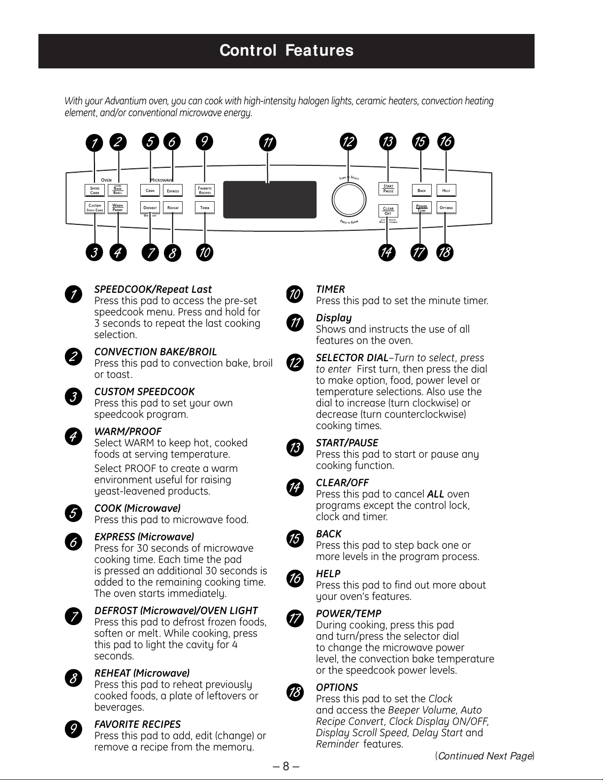
Control Features............................................................................................................................................................... 8
Control Panel Assembly.................................................................................................................................................26
Convection Heater Assembly and Thermistor....................................................................................................41
Damper Assembly............................................................................................................................................................35
Demo Mode.........................................................................................................................................................................15
Diagnostics and Service Information......................................................................................................................47
Door Assembly...................................................................................................................................................................25
High Voltage Transformer............................................................................................................................................33
Humidity Sensor................................................................................................................................................................43
Installation ...........................................................................................................................................................................16
Introduction......................................................................................................................................................................... 6
Left and Right Door Switch Assemblies..................................................................................................................44
Lower Heater Assembly ................................................................................................................................................40
Low Voltage Transformer .............................................................................................................................................29
Magnetron and Magnetron TCO................................................................................................................................34
Microwave Leak Test.......................................................................................................................................................48
Noise Filter ...........................................................................................................................................................................31
Noise Filter Fuse ...............................................................................................................................................................31
Nomenclature .................................................................................................................................................................... 5
Oven Removal / Partial Removal...............................................................................................................................24
Proof Feature......................................................................................................................................................................14
Schematics and Wiring Diagrams............................................................................................................................51
Sensor & Keypanel Failure Detection......................................................................................................................48
Service Test Mode.............................................................................................................................................................49
Speed Cook System.........................................................................................................................................................10
Standard Test Load..........................................................................................................................................................48
Surge Filter...........................................................................................................................................................................32
Surge Filter Fuses..............................................................................................................................................................32
Turntable Motor.................................................................................................................................................................43
Upper Heater Assembly ................................................................................................................................................38
Upper Heaters, Convection, and Oven Cavity TCOs.........................................................................................37
Vent Motor Assembly......................................................................................................................................................38
Warranty ..............................................................................................................................................................................53
https://appliancetechmanuals.com

– 5 –
Feature Pack
Designates Features - the higher
the number, the more features.
P S B 2 2 0 0 N B B
Brand
P = GE Profil e
Z = Monogram
Configuration
B = Wall Oven
C = Monogram Wall Oven
Product Color
BB = Black
SS = Stainless Steel
WW = White
Model Year Designator
Model Number
The nomenclature plate is located
on the inside door frame.
The mini-manual is located behind
the small access panel on the right
side of the oven.
Nomenclature
Nomenclature
The letter designating
the year repeats every
12 years.
Example:
T - 1974
T - 1986
T - 1998
Serial Number
The first two characters of the serial number
identify the month and year of manufacture.
Example: AR123456S = January, 2008
A- JAN 2008 - R
D - FEB 2007 - M
F - MAR 2006 - L
G - APR 2005 - H
H - MAY 2004 - G
L - JUN 2003 - F
M - JUL 2002 - D
R - AUG 2001 - A
S - SEP 2000 - Z
T - OCT 1999 - V
V - NOV 1998 - T
Z - DEC 1997 - S
GE Speedcook Technology
https://appliancetechmanuals.com

– 6 –
Introduction
The new Advantium oven uses breakthrough Speedcook technology to harness the power of light. The
Advantium oven cooks the outside of foods much like conventional radiant heat, while also penetrating the
surface so the inside cooks simultaneously. While halogen light is the primary source of power, a convection
system and ceramic heater assist in the cooking, with a "microwave boost” added in some cooking
algorithms. Foods cook evenly and fast, retaining their natural moisture.
Features and Benefits
Speedcook Oven - Delivers oven quality food up to four times faster than a conventional oven. No
preheating required.
True European Convection Oven - 1500-watt convection oven mode bakes and roasts at temperatures
ranging from 250 to 450°F.
Sensor Microwave Oven - 950-watt sensor microwave oven mode automatically delivers perfect cooking
results.
Warming Oven - Keeps prepared foods warm and fresh, and retains perfect moistness and crispness.
Proof Feature - Specialized mode allows dough to rise quickly.
16-in. Turntable - Removable metal and glass trays easily handle large casserole dishes.
Rounded Rear Wall - Allows complete turntable rotation of 9-in. x 13-in. casserole dish for even cooking.
Installation Flexibility - Fits either a 27-in. or 30-in. wall oven cabinet (installation kit included).
Preprogrammed Recipes - Provide quick and easy programming of over 175 Speedcook food selections.
Favorite Recipes - User can program up to 30 favorite recipes.
Multi-Level Cooking - Removable rack allows cooking of multiple dishes at once.
SPEED
COOK
CUSTOM
SPEED COOK
CONV
BAKE
WARM
COOK
DEFROST
OVEN LIGHT
EXPRESS
REHEAT
START
CLEAR
LOCK/UNLOCK
HOLD 5 SECONDS
BACK
POWER
HELP
OPIONS
FAVORITE
RECIPES
TIMER
T
U
R
N
T
O
S
E
L
E
C
T
P
R
E
S
S
T
O
E
N
T
E
R
OVEN DEMO LOCKED TURN DIAL REM MUTE TIMER
OVEN MICROWAVE
BROIL
PROOF TEMP
PAUSE
OFF
(Continued Next Page)
https://appliancetechmanuals.com

– 7 –
Turntable
The turntable must always be in
place, on the oven floor, for all
cooking. Be sure the turntable is
seated securely over the spindle
in the center of the oven with the
marked side facing up.
Metal Tray or Metal Grill Tray
Put food directly on the metal tray or
metal grill tray and place on the
turntable when using the speedcook,
broil, toast, warm and convection bake
features.
Wire Oven Rack
Put food directly on the metal tray or
in an oven-safe dish on the wire oven
rack only when convection baking on
two levels.
Clear Glass Tray
Place on turntable when using microwave
features. Place food or microwave-safe
cookware directly on tray.
Upper Halogen Lamps
Two 1200W halogen lamps cook food
from above in speedcook, broil and toast.
Window
Allows cooking to be viewed while
keeping microwaves confined in
the oven.
Door Handle
Pull to open the door.
Door Latches
The door must be securely latched fo
the oven to operate.
Lower Ceramic Heater
One 500W ceramic heater cooks foo
d
from the bottom in speedcook, broil
and toast.
Control Panel
The pads used to operate the oven
are located on the control panel.
Rear Convection System
One 1500W heating element cooks
food with a convection fan circulatin
g
the hot air throughout the cavity in
speedcook, broil, convection bake,
toast and warm.
https://appliancetechmanuals.com

– 8 –
Control Features
With your Advantium oven, you can cook with high-intensity halogen lights, ceramic heaters, convection heating
element, and/or conventional microwave energy.
SPEEDCOOK/Repeat Last
Press this pad to access the pre-set
speedcook menu. Press and hold for
3 seconds to repeat the last cooking
selection.
CONVECTION BAKE/BROIL
Press this pad to convection bake, broil
or toast.
CUSTOM SPEEDCOOK
Press this pad to set your own
speedcook program.
WARM/PROOF
Select WARM to keep hot, cooked
foods at serving temperature.
Select PROOF to create a warm
environment useful for raising
yeast-leavened products.
COOK (Microwave)
Press this pad to microwave food.
EXPRESS (Microwave)
Press for 30 seconds of microwave
cooking time. Each time the pad
is pressed an additional 30 seconds is
added to the remaining cooking time.
The oven starts immediately.
DEFROST (Microwave)/OVEN LIGHT
Press this pad to defrost frozen foods,
soften or melt. While cooking, press
this pad to light the cavity for 4
seconds.
REHEAT (Microwave)
Press this pad to reheat previously
cooked foods, a plate of leftovers or
beverages.
FAVORITE RECIPES
Press this pad to add, edit (change) or
remove a reci
p
e from the memor
y
.
TIMER
Press this pad to set the minute timer.
Display
Shows and instructs the use of all
features on the oven.
SELECTOR DIAL–Turn to select, press
to enter First turn, then press the dial
to make option, food, power level or
temperature selections. Also use the
dial to increase (turn clockwise) or
decrease (turn counterclockwise)
cooking times.
START/PAUSE
Press this pad to start or pause any
cooking function.
CLEAR/OFF
Press this pad to cancel ALL oven
programs except the control lock,
clock and timer.
BACK
Press this pad to step back one or
more levels in the program process.
HELP
Press this pad to find out more about
your oven’s features.
POWER/TEMP
During cooking, press this pad
and turn/press the selector dial
to change the microwave power
level, the convection bake temperature
or the speedcook power levels.
OPTIONS
Press this pad to set the Clock
and access the Beeper Volume, Auto
Recipe Convert, Clock Display ON/OFF,
Display Scroll Speed, Delay Start and
Reminder features.
(Continued Next Page)
https://appliancetechmanuals.com

– 9 –
Cooking Times
When Speedcooking preprogrammed foods, you
may see OPTIMIZING COOK TIME in the display
several seconds after you press START/ PAUSE. The
oven automatically senses the electrical voltage
level in your home and adjusts the cooking time up
or down for proper cooking.
Oven Heat
No preheating time is required during Speedcook
cycles. The oven begins cooking immediately.
The door and inside of the oven will be very hot. Use
caution when opening the door and removing food.
Be cautious of steam or vapor that may escape
from around the door.
Do not use cookware or coverings made of paper,
plastic, or foil when Speedcooking.
When cooking for an extended period of time, the
oven may automatically reduce the power levels to
maintain the appropriate level of oven heat.
Sounds
Clicks and a fan blowing are normal sounds
during cooking. The electronic control is turning
components on and off.
Interference
TV/radio interference might be noticed while using
the microwave, similar to the interference caused
by other small appliances. It does not indicate a
problem with the microwave. Move the radio or TV
as far away from the microwave as possible, or
check the position of the TV/radio antenna.
O NI GO OC
OV E N
9:5 8
V E N I S L . . .
AM
O P T I M ZNI I G EO O K T I MC
OV E N
9 : 5 5
Lights
When the oven is on, light may be visible around the
door or outer case.
The halogen lights will dim and cycle on and off
during a Speedcook cycle, sometimes even at full
power levels. This is normal. The oven senses the
heat level and adjusts automatically.
The oven cavity light will not come on during any
cooking cycle but will come on whenever the door
is opened. To view food while cooking, press the
DEFROST pad, then the inner halogen heater will
light the oven cavity for 4 seconds.
Cooling Fans
The fans will be on during cooking. At the end of
cooking, the fans may continue to run for a short
time to cool internal components. The fans will
automatically shut off when the internal parts of the
oven have cooled. The oven vent will emit warm air
while the oven is on.
https://appliancetechmanuals.com

– 10 –
Speed Cook System
(Continued Next Page)
Halogen Lamp and Ceramic Heaters
Two 1200-watt halogen bulbs cook food from above.•
One 500-watt ceramic heater cooks food from below.•
Rear Convection Heat Element
A 1500-watt convection element operates when using convection bake.•
The 1500-watt convection element is automatically added with certain foods.•
Microwave
A microwave “boost” is automatically added with certain foods.•
The oven can also be used as a 950-watt microwave oven.•
https://appliancetechmanuals.com

– 11 –
(Continued Next Page)
Speedcook Overview
Upper Heaters
The upper heating assembly consists of two 1200-
watt halogen heaters. The halogen heaters provide
radiant heat, which browns the outside of the food
while sealing in moisture and flavor. These heaters
are operated by the control board based on power
levels and duty cycle, and only operate in the
Speedcook mode. However, during any cook mode
the inner heater can be energized for 4 seconds by
pushing the DEFROST pad on the control panel. This
will illuminate the oven cavity long enough for the
customer to see the contents inside the oven.
Lower Heater
The lower heater is a 500-watt ceramic heater.
It operates in Speedcook, oven/bake, and warm
modes. The lower heater assists in browning foods
on the bottom.
Convection System
The 1500-watt convection system consists of a
convection heater and fan that operate when
using convection bake, broil, or toast, and assists in
heating the oven when using Speedcook.
Microwave Energy
Caution: When cooking in Microwave mode, always
use the glass tray.
The Advantium 240 provides 950 watts of
microwave power, which is delivered directly
into the oven cavity to work independently, or in
conjunction with other cooking cycles. As the food
rotates on the oven turntable, microwave energy is
evenly distributed to all portions of the food.
Sensor Cooking
Advantium’s microwave mode features sensor
cooking, which automatically selects cook times
and power levels. A humidity sensor detects the
increasing humidity released during cooking, senses
when the food is done, and shuts the oven off at the
appropriate time. Sensor cooking is not available for
5 minutes immediately following Speedcook.
Power Levels
Advantium uses power from high-intensity halogen
lamps, a ceramic heater, microwave energy, as
well as convection heating to simultaneously cook
foods evenly and quickly (average of one-fourth the
time of a conventional oven) to seal in moisture and
flavor.
Power levels are selected with the selector dial and
can be adjusted before cooking or during cooking.
When using preset menu foods, the power levels
are already selected. However, power levels can be
adjusted when cooking both preset menu food and
when manual cooking.
Power levels from 0 to 10 can be selected and
adjusted independently for the upper halogen
lamps (pair), lower ceramic heater (single),
microwave energy, and convection heating. When
selecting an upper halogen lamp power level, the
power level can only be selected for the pair. You
cannot select power levels for the inner and outer
independently.
The power levels control the percentage of ON time
for the upper halogen lamp pair, the lower ceramic
heater, and microwave high voltage circuit. During
Speedcook, the operation of the convection heater
is based on temperature. The convection heater will
cycle on and off if needed, and the convection fan
will operate continuously throughout Speedcook.
UPPER POWER (U) controls the upper halogen
heaters. Select a higher setting for such foods as
pizza and baked goods. Select a lower setting for
foods, such as casseroles, meats, and fish.
SP:
OP EP
OV E N
0 8
e l etU R W E R
c
Up p e r =
TURNDIAL
https://appliancetechmanuals.com

– 12 –
SP:
O
W EO
OV E N
0 5
e l etL R W E R
c
Lo w e r =
TURNDIAL
SP:
O
C RI
OV E N
o w
e l etM O W E R
c
Mi c r o P
TURNDIAL
er=0 3
SPO
C T
E
OV E N
io
e t O V I W E RC
Co n v e t
TURNDIAL
n=0 7
NON
c
PS:
EE L
V
OV E N
05
O W E L E S T OT
R
U=0 8 L=CM =03=0 7
MICROWAVE (M) controls operation of the
microwave. Select a higher setting to shorten
cooking time for dense or heavy food, such as
whole chicken. Select a lower setting for delicate
foods, such as breads or foods requiring longer
times.
LOWER POWER (L) controls the lower ceramic heater.
Select a higher setting for thick or dense foods that
may not cook quickly in the center. Select a lower
setting for thin foods, such as cookies.
CONVECTION (C) controls the heat output of the
convection system. Select a lower setting for more
delicate foods that cook at lower temperatures.
Select a higher setting (6 or above) for more robust
foods that cook at temperatures above 350°F.
The display will show a summary of the power levels
before cooking.
% On Time
32 Second Duty Cycles
96
30% 50% 80% 30% 50% 80%
U = 8
L = 5
M = 3
03264
30% 50% 80%
U = 8
L = 5
M = 3
U = 8
L = 5
M = 3
Convection Cooking ChartConvection Cooking Chart
Power Level Temperature Operation
0 Room See Note 1
1 300°F See Note 2
2 310°F See Note 2
3 320°F See Note 2
4 330°F See Note 2
5 340°F See Note 2
6 350°F See Note 3
7 375°F See Note 3
8 400°F See Note 3
9 425°F See Note 3
10 450°F See Note 3
Notes:
Convection element not ON.1.
Reaches temperature and then cycles at2.
temperature for remainder of programmed time.
Reaches temperature and then cycles at 350°F3.
for remainder of programmed time.
Each convection power level setting directs the
convection cooking system to operate within certain
parameters as shown in the table below.
The programming on the smart board which
controls the upper halogen lamps (pair) and the
lower ceramic heater, as well as the high voltage/
magnetron circuits, operates on a duty cycle of
32 seconds. This means the power level you select
for each component controls the percentage of
ON time during each 32-second period of time. For
example, when the oven is set on power level 10,
both the inner and outer halogen heaters will stay
on 100% of the time. On power levels less than 10,
both heaters will cycle together.
In the following example, the upper halogen lamps
would cycle for 80% of each 32-second period,
the lower ceramic heater would cycle at 50% of
each 32-second period, and the microwave high
voltage circuit would be energized for 30% of each
32-second period.
(Continued Next Page)
https://appliancetechmanuals.com

– 13 –
(Continued Next Page)
Voltage Time Change (Seconds)
108 +180
110 +150
112 +120
114 +90
116 +60
118 +30
120 0
122 -21
124 -42
126 -63
128 -84
130 -105
132 -126
Voltage Compensation Chart
Voltage Compensation
Note: Voltage compensation only occurs when
using a preselected menu item in Speedcook. These
items require compensation for accurate and
consistent cooking results.
Voltage fluctuations in the power supply can cause
inconsistencies in cooking. The main PCB measures
line voltage at the start of each Speedcooking
selection and adjusts the cooking time to achieve
consistent results. Optimal line voltage, where no
voltage compensation occurs, is 120 VAC. Above
120 VAC, time is subtracted from the recipe. Below
120 VAC, time is added to the recipe. The amount of
voltage compensation required is dependent upon
the incoming voltage at the start of the cooking
cycle and the particular Speedcooking selection
that is chosen.
Voltage compensation occurs after approximately 5
seconds of cooking operation. The display will show
OPTIMIZING COOK TIME. The time will flash and
then display the new adjusted time, based on the
amount of voltage compensation required.
Voltage compensation only occurs during
Speedcook operation and only occurs once during
the cooking cycle (at initial start of Speedcook
operation).
O P T I M ZNI I G EO O K T I MC
OV E N
9 : 5 5
Note: Voltage compensation should be within 20
seconds of values in table.
The following chart shows the predicted
compensation times based on a 5-minute
Speedcook selection (e.g., Biscuits, Refrigerated,
Large).
SMART BOARD
CN5
Voltage Compensation Circuit
CN4CN4
https://appliancetechmanuals.com

– 14 –
Proof Feature
The purpose of the PROOF feature is to help dough
rise at the correct temperature inside the oven. To
activate the proof feature, press the WARM/ PROOF
pad, then turn the dial to PROOF BREAD and press
the dial to start. The following will occur:
• The convection fan and convection heater come
on immediately.
The convection element cycles 11 seconds•
on and 21 seconds off for first 30 minutes at
temperature around 80°F, then after 30 minutes
element is 100% on only if the temperature is
below 80°F and cavity is calling for heat.
• The convection fan continues to operate and, if
needed, the convection heater will come on.
Note: In PROOF, there is not an upper temperature
set point defined. If the temperature is above 80°F,
then the element does not come on at all until the
temperature is below 80°F. (Ideally you don't want
a temperature over 100 - 110°F because you will
kill the yeast.) But unless there is something wrong
with the oven control, the element, or the actual
environment is above 100°F, PROOF should never
reach this condition. If an inoperative convection
heater in the PROOF mode is suspected:
1. Disconnect power.
2. Remove the rear access cover.
3. Remove the thermistor from the convection
heater assembly.
4. Lower the thermistor temperature by placing a
chilled or frozen item against the thermistor.
5. Connect power and enter proof mode.
6. Check for approximately 120 VAC (12.3 Amps) at
the convection heater.
Thermal Compensation
Note: Thermal compensation only occurs once and
only when using a preprogrammed menu item in
Speedcook. These items require compensation for
accurate and consistent cooking results.
When cooking several food items consecutively, the
temperature in the oven may become very high.
When Speedcooking, the Advantium automatically
compensates for the increased temperature by
reducing the power levels based on the following
rules during each 32-second duty cycle.
Upper Thermal Sensor
Note
Thermal Compensation occurs only ONCE and•
when using a pre-programmed recipe.
Activates when oven cavity temp is greater than•
220°F.
• Compensation rules:
UPL = Upper Power Level,
LPL = Lower Power Level,
CPL = Convection Power Level.
No compensation if cook time is less than 2•
minutes 30 seconds or greater than 13 minutes.
If cavity temp less than 220°F, no compensation.•
If cavity temp greater than 220°F but less than•
288°F, reduce UPL by 1, LPL by 2, and CPL by 2.
If cavity temp greater than 288°F but less than•
340°F, reduce UPL by 1, LPL by 3, and CPL by 2.
If cavity temp greater than 340°F, reduce UPL by•
1, LPL by 3, and CPL by 3.
Upper thermal sensor (blue and white wires) is•
used for thermal compensation.
https://appliancetechmanuals.com

– 15 –
Demo Mode
The sales demo mode will allow dealers to demonstrate all oven functionality with one exception. (See #1
below.)
The sales demo mode can only be entered during the initial SELECT TIME display that occurs when the unit
powers up after a long (greater than 60 seconds) power outage.
DEM O O
ME
4:
D
0 0 P M
DE M O
ST I
OC
L
TU R N
0:00
eletK M E:
cC
0
D I A L
When sales demo mode is initiated, 2 short-beeps are sounded and all oven functions will operate with the
following exceptions;
1. No power shall ever be applied to the heaters, halogen lamps, magnetron high voltage transformer, or
Inrush control relays. The control relays for any of these loads shall not be switched during sales mode.
However, if you press the DEFROST pad while in a demo cook mode, the inner halogen light will come on
for 4 seconds.
2. The DEMO icon will be lit whenever the unit is in sales mode regardless of settings or the feature being
selected.
The sales demo mode is cleared by holding the POWER / TEMP and START pads down at same time for a
full 3 seconds. The sales mode can only be cleared during the same initial SELECT TIME display that occurs
when the unit powers up after a long (greater than 60 seconds) power outage. After 5 seconds elapse, all
functions of the oven will return to normal operation.
When power-up occurs, software will check the special sales demo identifier code. If the code is set, then the
oven will stay in the sales demo mode. This will prevent the unit from powering back up to a normal mode if
power to the salesroom had gone off.
The sales demo mode will be initiated by holding the POWER / TEMP and START / PAUSE pads down at the
same time for a full 3 seconds.
https://appliancetechmanuals.com

– 16 –
Advance Planning
These ovens may be installed directly into a 30”•
wide oven cabinet.
Cutout dimensions are NOT the same for•
installation with or without an accessory
storage drawer. Make sure to use the correct
cutout when preparing the opening.
Note: Model ZSC2202 CANNOT be installed with
an accessory storage drawer. Refer to Installation
Instructions, Pub. 49-40574-1.
IMPORTANT―This oven is not approved for use
above another built-in Advantium Speedcook oven,
a side by side installation or below a countertop.
For personal safety, this oven cannot be•
installed in a cabinet arrangement such as an
island or peninsula.
The oven must be installed at least 36-3/4"•
above the floor.
Allow for clearance to adjacent corners, walls,•
drawers, etc.
Cabinets installed adjacent to wall ovens•
must have an adhesion spec of at least 194ºF
temperature rating.
The oven must be securely installed in a cabinet•
that is firmly attached to the house structure.
Weight on the oven door could cause the oven
to tip and result in injury. Never allow anyone to
climb, sit, stand or hang on the oven door.
If installing the drawer accessory, the drawer•
must be assembled to the oven prior to
installation into the cabinet. Refer to Installation
Instructions, Pub. 49-40574-1.
Electrical Requirements
Single Speedcook Installation
Product rating is 120/208 or 120/240 volt, 60 Hz,
30 amps. This product must be connected to a
supply circuit of the proper voltage and frequency
and protected by a time delay fuse or circuit
breaker. Power should be supplied from a separate,
dedicated 30-ampere branch circuit.
Installation
Wire size must conform to the requirements of the
National Electrical Code or the prevailing local code.
Combined Speedcook and Wall Oven Installation
When installed in combination with a GE/Monogram
single wall oven, use separate electrical junction
boxes.
Refer to single oven installation instructions for
electrical requirements of that product.
These connections must be made by a qualified
electrician. All electrical connections must meet
National Electrical Code or prevailing local codes.
Combined Speedcook and Warming Drawer
Installation
When installing the Speedcook oven over a GE or
Monogram electric warming drawer, a separate
120V, 60Hz, properly grounded receptacle must be
installed. See instructions packed with the warming
drawer.
WARNING
The electrical power to the oven branch circuit•
must be shut off while line connections are
being made.
Use copper wiring only.•
Electrical ground is required on this appliance.•
The free end of the green wire (ground wire)
must be connected to a suitable ground. This
wire must remain grounded to the oven.
If cold water pipe is interrupted by plastic, non-•
metallic gaskets, union connections or other
insulating materials, DO NOT use for grounding.
DO NOT ground to a gas pipe.•
DO NOT have a fuse in the NEUTRAL or•
ROUNDING circuit. A fuse in the NEUTRAL or
ROUNDING circuit could result in an electrical
shock.
Check with a qualified electrician if you are in•
doubt as to whether the appliance is properly
grounded.
Failure to follow these instructions could result in
serious injury or death.
https://appliancetechmanuals.com

– 17 –
Component Locator Views
Front View
(Continued Next Page)
Control Panel Assembly
Convection Fan Assembly
Turntable
High Voltage Transformer
Magnetron
Capacitor
Diode
Damper Assembly
Low Voltage Transformer
Upper Heater Assembly
Relay Board
Power Board
Top View
Vent Motor
UHH1 TCO
UHH2 TCO
Surge Filter
Circulation Blower
https://appliancetechmanuals.com

– 19 –
Noise Filter
Right Side Door Switch Assembly
Magnetron TCO
Control Panel Assembly
Right Side View
(Continued Next Page)
Surge Filter
Control Panel Assembly (Shown separated)
Control Board
Relay Board Power Board
Selector Board Upper Display Board
Control Panel
Low Voltage Transformer
Control Panel Bracket
Lower Display Board
Circulation Blower
https://appliancetechmanuals.com

– 20 –
Power Board
CN3 - Low Voltage Transformer #1 (Secondary Windings)
CN7 - Door Switch, Damper Switch
CN8 - Humidity Sensor
CN9 - Thermistor
CN21 - Control Board
Control Boards and Panel Connections
(Continued next page)
Relay Board
CN1
CN5
RY7
RY7 - Inner Halogen Heater
RY9 - Outer Halogen Heater
RY11 - Ceramic Heater
RY12 - Convection Heater
RY14 - Magnetron
CN3
CN9CN8
CN7
CN21
RY9 RY11 RY12 RY14
CN6
CN20
CN101
CN1 - Low Voltage Transformer #1 (Primary Winding)
CN5 - Primary Interlock, Noise Filter, Oven
Lamp
CN6 - Circulation Motor, Damper Motor, Convection
Motor, Vent Motor, Turntable Motor
CN20 - Control Board
CN101 - Power Board
https://appliancetechmanuals.com
Other manuals for 240
2
This manual suits for next models
7
Table of contents
Other GE Oven manuals

GE
GE Monogram ZET1PHSS User guide

GE
GE Advantium PSB1200BB User manual

GE
GE Advantium PSB9100 User manual

GE
GE PLS624RT Operating instructions

GE
GE JKP90 User manual

GE
GE Profile Advantium PSB9240SFSS User instructions

GE
GE CT9570 User manual

GE
GE JRS04GP1 User manual

GE
GE JKP75SM Manual

GE
GE Profile PK916DR Manual
Popular Oven manuals by other brands

Zanussi
Zanussi ZOB 641 Instruction booklet

Philco
Philco POC 828 user manual

Bosch
Bosch HBG517E 1R Series User manual and installation instructions

Bosch
Bosch HBG656R 6B Series instruction manual

Bosch
Bosch VGD553FB0 User manual and installation instructions

Hamilton Beach
Hamilton Beach 31508-220 use & care