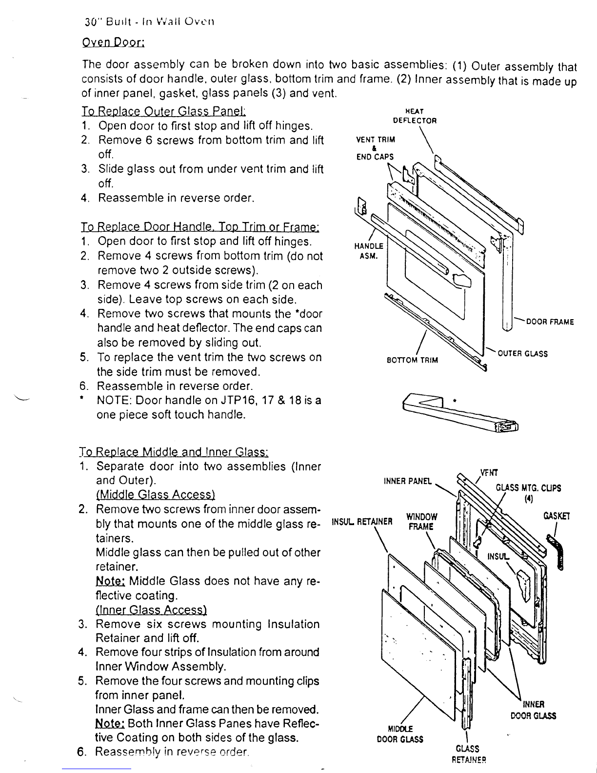
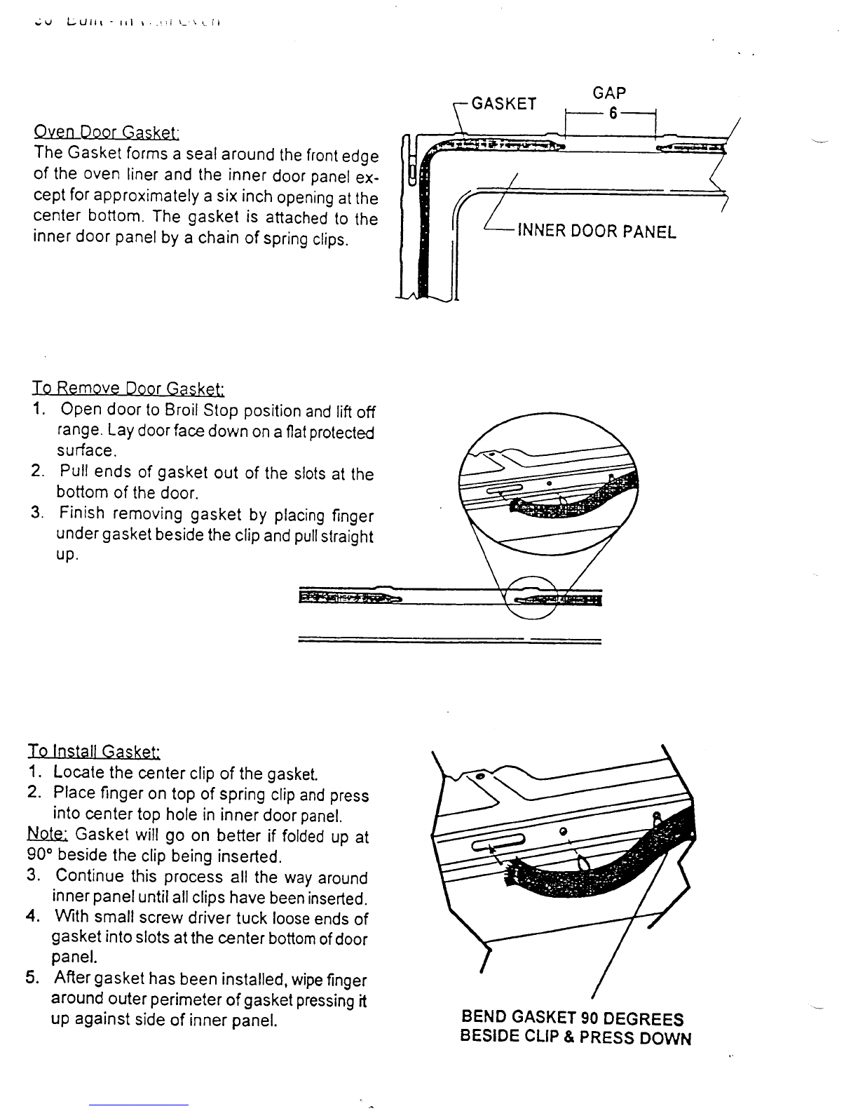
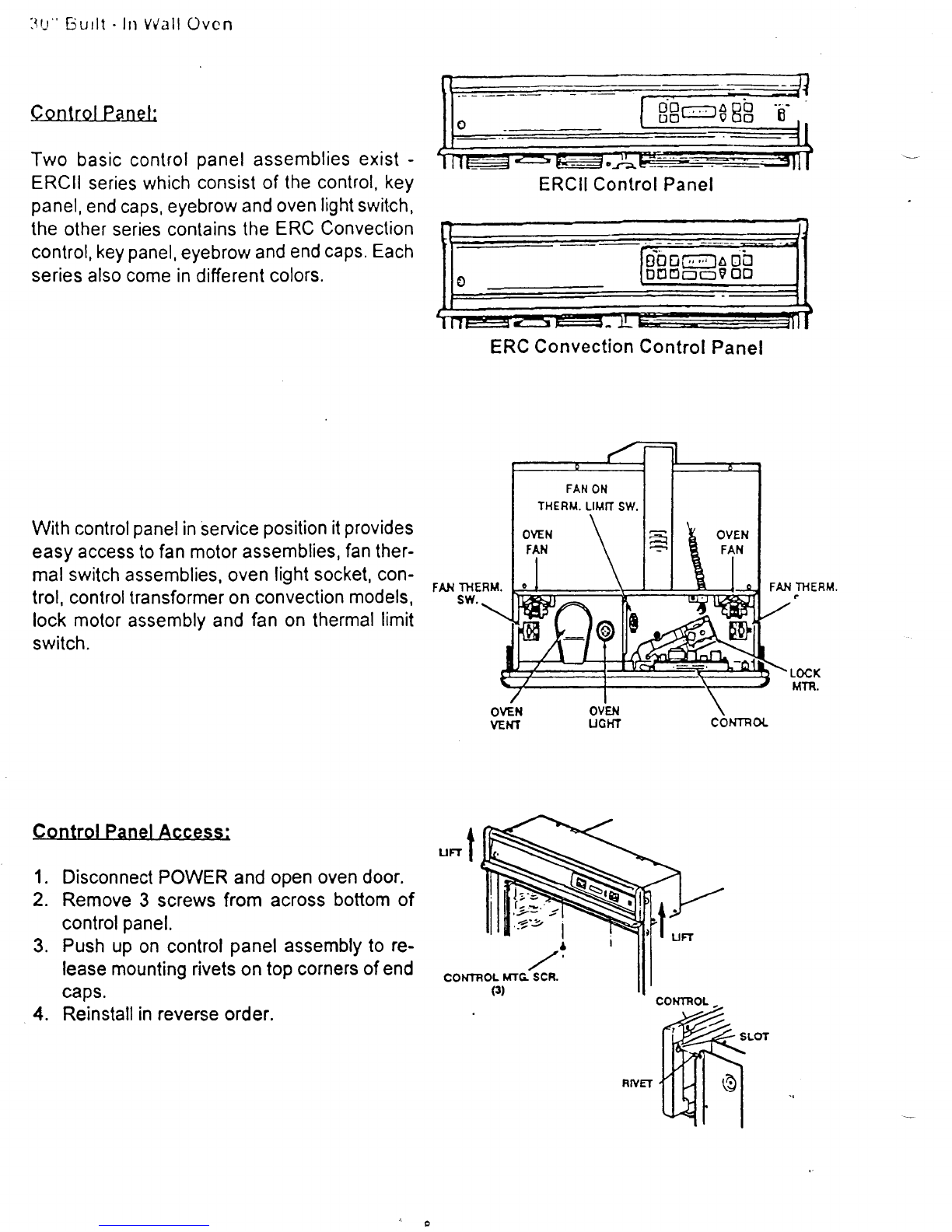
t-
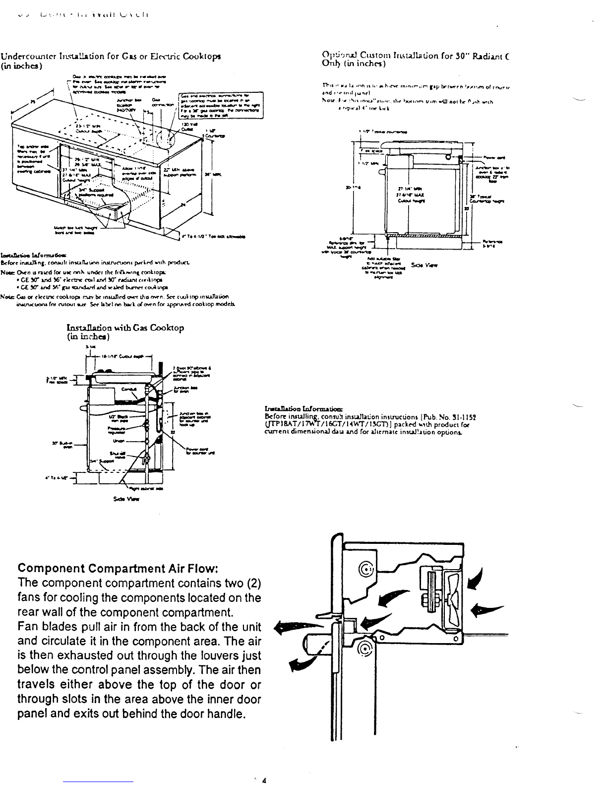
Undcrcountcr In-strlhtion for Crs or EJecrricCooltopa
(h iocbce)
t, Ya
qr
bEEb{n
HTIE f laa.rrl't-€.s
lx^irdco bfo|@d*
D<hrc inallng. coult inulLtirn inrrruffir pr(l.d rrrh FrodxL
Nc Or<n u nrd fq ur mlr un&r thc frrl\nrnl coltop
. GE !f vd !6'cLc ol rrx! !O'adi:nt <rr'ttopr
. Ct g .td 5'6r orr3rrd rnd rrJcd hrr <ciupr
Nac Gr a ckcn rolrop r* b< rnc.ncd F thg ffn. 5.< c,rl tcp rnuJhdm
irwm (o rut@t E S+c bS<l m ta<L o{*n fo rpfrutd (€ltoP ttEdc}r
Insulhtion uitb Gas
Cooktop
(io tcclee)
Optirnd Crr.stonllnsreJtation
for 30" R.ldjenr
(
Orrf {in inc}cs)
flrr ,' rr lr ,d^ rr
l,.r h,G 3rp brr*rn trat.,6o(.N"t.
rad r.z rr,l lurcl
!\ok. 1,, t\,r,nul'rrr,r:. rlrr lur,ro uro r{ll aor lr irrf. srh
r..r.rl a.
rd l,(l
r r?rEsJE
fie
b€aE -
q gttr
*Er66.4t
Yr EraL
J,:i"-ru Sor
vn
FtubS
O- t -t@E--4*
ahF l-*dFr-.g
\ tsv6 b.v-EtFt
ilqE4€
'T
I
-l-
J
>tzn
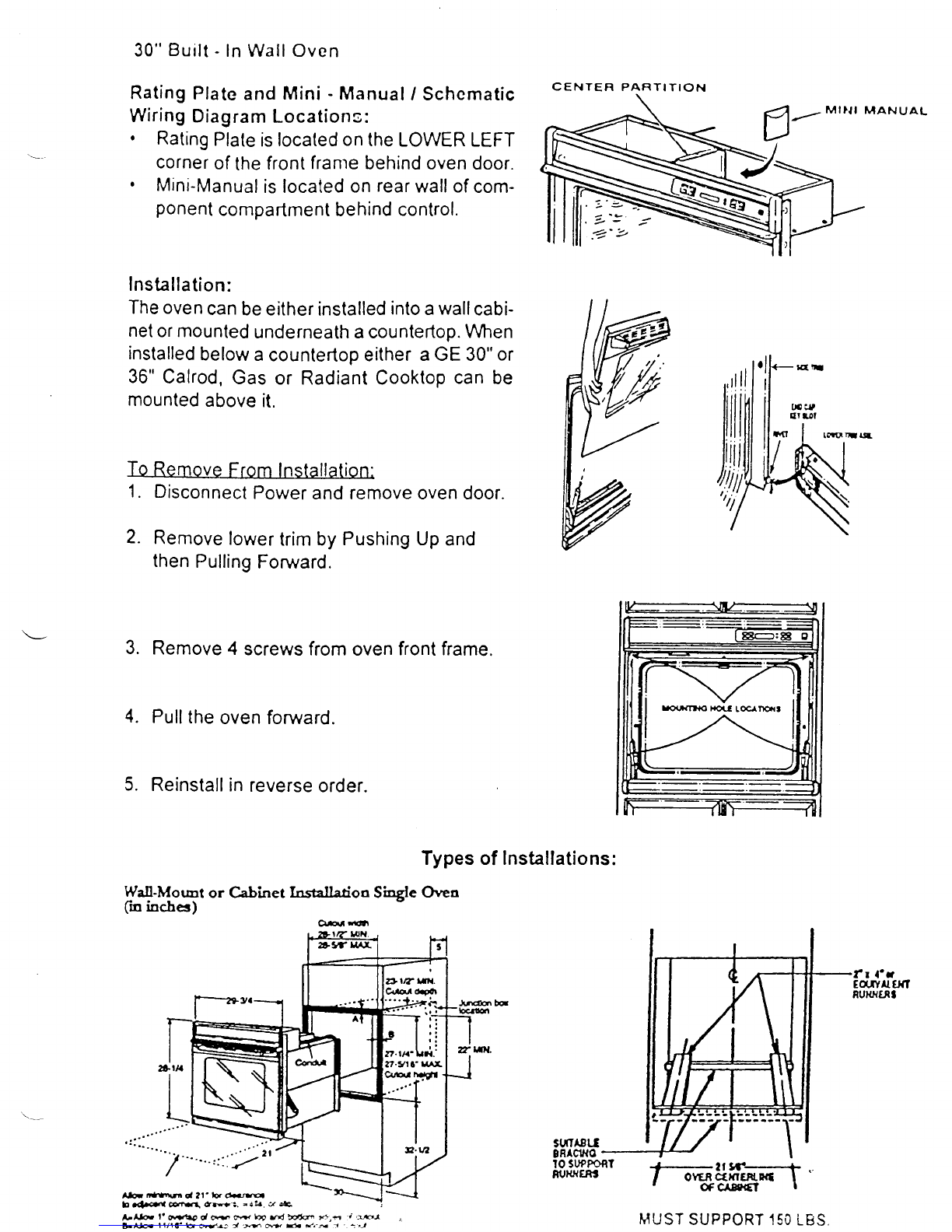
Component
Compartment
AirFlow:
The
component
compartmentcontains
two
(2)
fans
for
cooling
thecomponentslocatedon
the
rear
wall
of
thecomponent
compartment.
Fan
blades
pull
airin
fromthe
backofthe
unit
andcirculate
it
inthe
componentarea.Theair
isthen
exhausled
outthroughthe
louvers
just
belowthe
control
panelassembly.
Theair
then
travelseither
above
thetopofthedoor
or
through
slotsin
theareaabove
the
inner
door
panel
and
exitsoutbehind
thedoorhandle.
Irallrrion lalorantir
Bcfort irudling, conwh insuJlarjon
inrtrucdontIPub.
No.3l.l I5?
0m I8AT/ InAT / |6T / | lUT / lJQf) ! pacled rrrh producr for
currcnt dimenrioneld:u andfor rJrcmatiinrreJhdon
opuonr
l;-o. o
I qltF
lb
I
,rfl
Sd\Ai