Installation
Instructions
CONTENTS
General
information
Important
Safety
INStrUCtiOnS
0.0...
ssesscssesseeeeneees
3
Electrical
RequireMents
..............esseceseseceneneneseeeseneneees
3
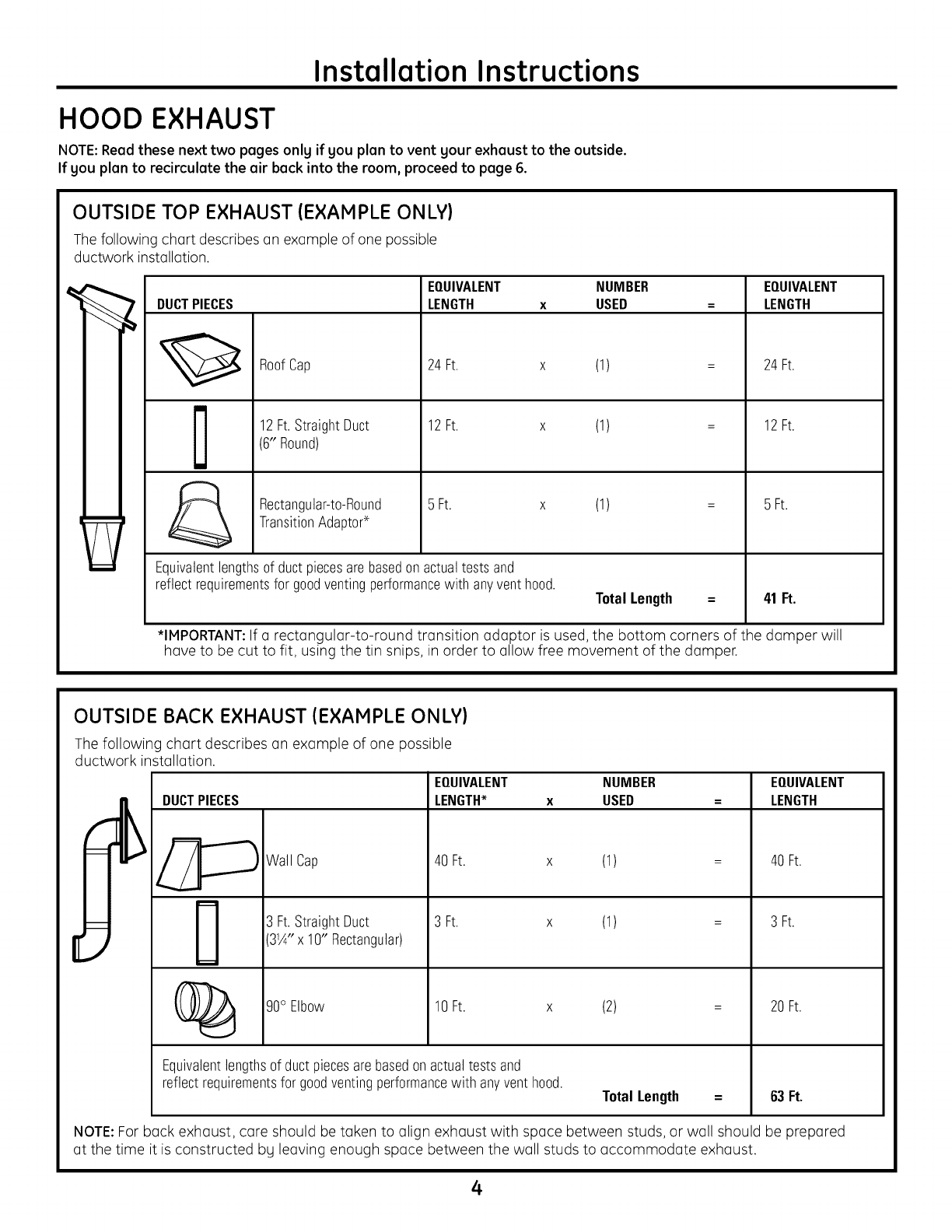
Hood
Exhaust...
4,5
Damage
-
Shipment/Installation
00...
eeeeeeeeeee
6
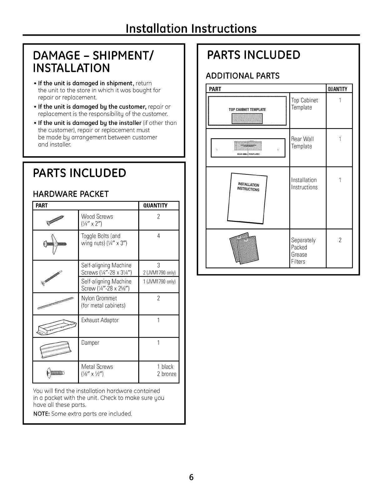
Parts
Included
wee
6
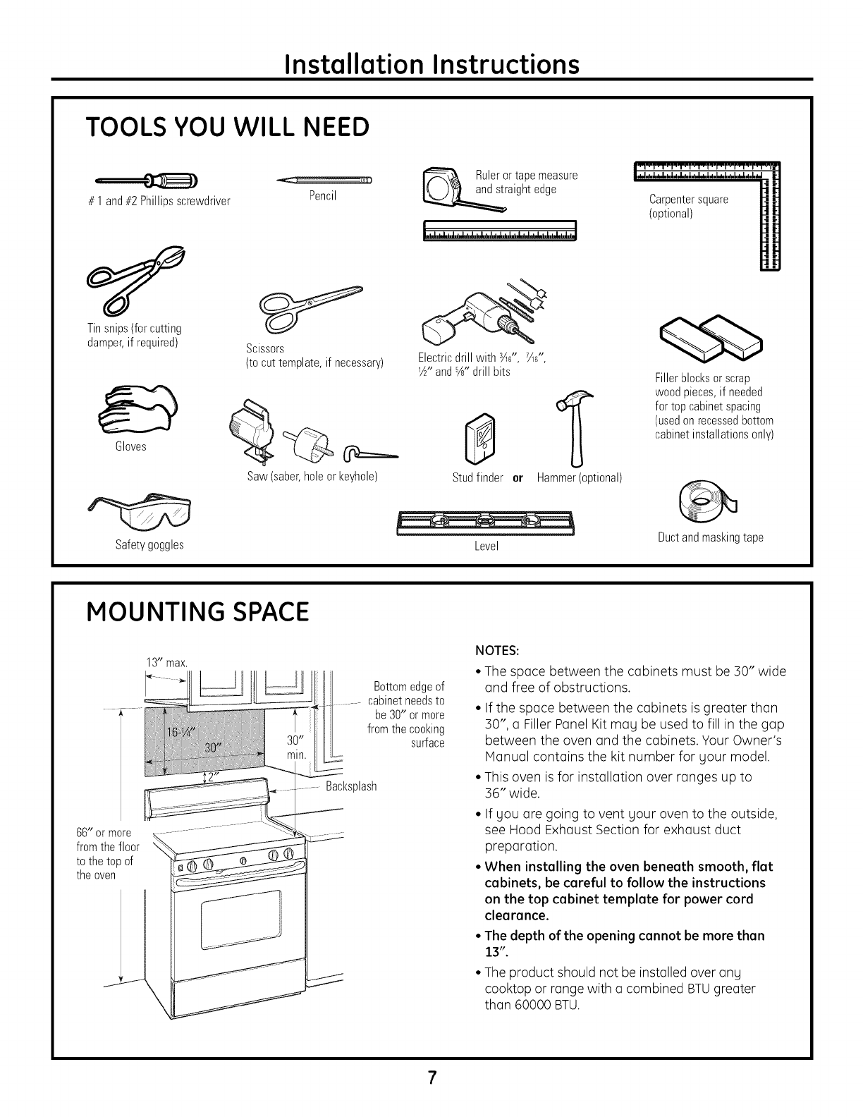
Tools
You
Will
Need
oe
escscssecsessecsvesessseevenesssseeeee
7
Mounting
Space
wee
7
Step-by-step
installation
guide
Placement
of
Mounting
Plate
2.0...
eeseseeereeee
8-10
Removing
the
MOUNTING
PlOte
....essseeeeeeeee
8
Finding
the
Wall
Studs...
esesssssssseseessssesereree
8
Determining
Wall
Plate
LOCAtION
oe
eeeeeeeeee
9
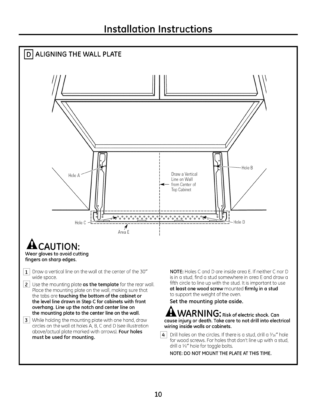
Aligning
the
Wall
Plate
1...
sssssssssssssssssssssnsees
10
Installation
Types
11-22
Outside
Top
ExXNCUSt
....cesecececececeeseseseserereees
12-14
Attach
Mounting
Plate
to
Wall
oe
12
Preparation
of
Top
Cabinet
......essesereree
13
Assemble
and
Install
Adaptor
oes
13
MOUNE
the
OVEN
weccececcssesesessessesseees
13,14
Adjust
the
Exhaust
Adaptor...
eesseseees
14
CONNECTING
DUCTWOTK
.....
eeeseeeesseeeceseeeceseees
14
B
Outside
BACK
EXNCAUST
os
essessseessecsseveseeee
15-18
Preparing
Rear
Wall
for
Outside
BACK
EXNAUSt....esessecsesscsreneseeee
15
Attach
Mounting
Plate
to
Wall
..........
15,
16
Preparation
of
Top
Cabinet
.......essesereeee
16
Adapting
Blower
for
Outside
BOCK
EXNCUSE
wecccccssccscsescscsseeseeseseesceseees
16,
17
MOUNE
the
OVEN...
cecsecssesessessesscessessessessenes
18
RECIFCUICTING
«os
sesesesesecececececececececeseceeeatereees
19-22
Attach
Mounting
Plate
to
Wall
«0...
19
Preparation
of
Top
Cabinet
....eeessseseees
19
Adapting
Blower
for
RECIPCUIOTION
vce
eeesesecssesseseeseeeee
20,
21
MOUNE
the
OVEN
wececeeceseseceseeseeseeseees
21,
22
Installing
the
Charcoal
Filter
ot
essseseees
22
Before
You
Use
Your
OVO@N
oo.
essescsscseesessscsresesseonees
23
SeccION
EN
ESPAAOL
........
es
escesessesseseseesesnesesneneneens
25-47