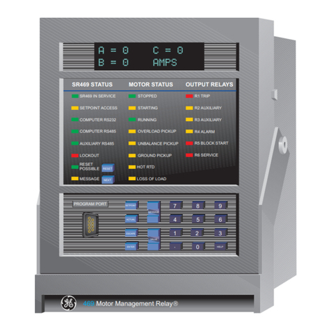
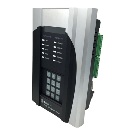
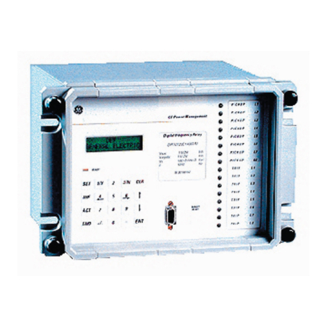
GE Masoneilan 469 Series Use and care manual

Software revision: 5.2x
GE part number: 1601-0152-AD
GE publication code: GEK-106491M
GE Grid Solutions
650 Markland Street
Markham, Ontario
Canada L6C 0M1
Tel: +1 905 927 7070 Fax: +1 905 927 5098
Internet: http://www.gegridsolutions.com
*1601-0152-AD*
GE
Grid Solutions
469 Motor Management Relay
Communications Guide

© 2017 GE Multilin Incorporated. All rights reserved.
GE Multilin — 750/760 Feeder Management Relay instruction manual for revision 5.2x
750/760 Feeder Management Relay, is a registered trademark of GE Multilin Inc.
The contents of this manual are the property of GE Multilin Inc. This documentation is
furnished on license and may not be reproduced in whole or in part without the permission
of GE Multilin Inc. The content of this manual is for informational use only and is subject to
change without notice.
Part numbers contained in this manual are subject to change without notice, and should
therefore be verified by GE Multilin Inc. before ordering.
Part number: 1601-0152-AD (March 2017)

469 MOTOR MANAGEMENT RELAY – COMMUNICATIONS GUIDE TOC-2
Table of Contents
MODBUS PROTOCOL Electrical Interface ...........................................................................................................................................1
Modbus RTU Protocol .....................................................................................................................................1
Data Frame Format and Data Rate.........................................................................................................2
Data Packet Format........................................................................................................................................2
CRC-16 Algorithm.............................................................................................................................................3
Timing ....................................................................................................................................................................4
MODBUS FUNCTIONS Supported Functions ......................................................................................................................................5
Read Relay Coil / Digital Input Status .....................................................................................................5
Read Setpoints and Actual Values ...........................................................................................................7
Execute Operation ...........................................................................................................................................8
Store Single Setpoint.......................................................................................................................................8
Read Device Status..........................................................................................................................................9
Loopback Test................................................................................................................................................. 10
Store Multiple Setpoints..............................................................................................................................10
Performing Commands .............................................................................................................................. 11
Error Responses .............................................................................................................................................12
MODBUS MEMORY
MAP
Memory Map Information......................................................................................................................... 13
User-Definable Memory Map Area ....................................................................................................... 13
Event Recorder ............................................................................................................................................... 15
Waveform Capture....................................................................................................................................... 15
469 Memory Map..........................................................................................................................................19
Format Codes............................................................................................................................................... 109
DEVICENET
PROTOCOL
Overview......................................................................................................................................................... 124
Poll Data.......................................................................................................................................................... 124
Change of State (COS) .............................................................................................................................. 124
DeviceNet Objects...................................................................................................................................... 125
469 Specific Objects.................................................................................................................................. 131
DeviceNet Data Formats ........................................................................................................................ 140

TOC-2 469 MOTOR MANAGEMENT RELAY – COMMUNICATIONS GUIDE

469 MOTOR MANAGEMENT RELAY – COMMUNICATIONS GUIDE 1
469 Motor Management Relay
Communications Guide
GE
Grid Solutions
Communicatio ns Guide
Modbus Protocol
Electrical Interface
The hardware or electrical interface is one of the following: one of two 2-wire RS485 ports
from the rear terminal connector or the RS232 from the front panel connector. In a 2-wire
RS485 link, data flow is bidirectional. Data flow is half duplex for both the RS485 and the
RS232 ports. That is, data is never transmitted and received at the same time. RS485 lines
should be connected in a daisy chain configuration (avoid star connections) with a
terminating network installed at each end of the link, i.e. at the master end and at the slave
farthest from the master. The terminating network should consist of a 120 Ωresistor in
series with a 1 nF ceramic capacitor when used with Belden 9841 RS485 wire. The value of
the terminating resistors should be equal to the characteristic impedance of the line. This
is approximately 120 Ωfor standard #22 AWG twisted pair wire. Shielded wire should
always be used to minimize noise. Polarity is important in RS485 communications. Each ‘+’
terminal of every 469 must be connected together for the system to operate. See Chapter
2 of the 469 manual for details on correct serial port wiring.
Modbus RTU Protocol
The 469 implements a subset of the AEG Modicon Modbus RTU serial communication
standard. Many popular programmable controllers support this protocol directly with a
suitable interface card allowing direct connection of relays. Although the Modbus protocol
is hardware independent, the 469 interfaces include two 2-wire RS485 ports and one
RS232 port. Modbus is a single master, multiple slave protocol suitable for a multi-drop
configuration as provided by RS485 hardware. In this configuration up to 32 slaves can be
daisy-chained together on a single communication channel.

2469 MOTOR MANAGEMENT RELAY – COMMUNICATIONS GUIDE
MODBUS PROTOCOL COMMUNICATIONS GUIDE
The 469 is always a slave. It cannot be programmed as a master. Computers or PLCs are
commonly programmed as masters. The Modbus protocol exists in two versions: Remote
Terminal Unit (RTU, binary) and ASCII. Only the RTU version is supported by the 469.
Monitoring, programming and control functions are possible using read and write register
commands.
Data Frame Format and Data Rate
One data frame of an asynchronous transmission to or from an 469 is default to 1 start bit,
8 data bits, and 1 stop bit. This produces a 10 bit data frame. This is important for
transmission through modems at high bit rates (11-bit data frames are not supported by
Hayes modems at bit rates of greater than 300 bps). The parity bit is optional as odd or
even. If it is programmed as odd or even, the data frame consists of 1 start bit, 8 data bits,
1 parity bit, and 1 stop bit.
Modbus protocol can be implemented at any standard communication speed. The 469
RS485/RS232 ports support operation at 1200, 2400, 4800, 9600, and 19200 baud.
Data Packet Format
A complete request/response sequence consists of the following bytes (transmitted as
separate data frames):
•SLAVE ADDRESS: This is the first byte of every transmission. This byte represents the
user-assigned address of the slave device that receives the message sent by the
master. Each slave device must be assigned a unique address and only the addressed
slave responds to a transmission that starts with its address. In a master request
transmission the Slave Address represents the address of the slave to which the
request is being sent. In a slave response transmission the Slave Address represents
the address of the slave that is sending the response. Note that a master transmission
with a Slave Address of 0 indicates a broadcast command. Broadcast commands can
be used for specific functions.
•FUNCTION CODE: This is the second byte of every transmission. Modbus defines
function codes of 1 to 127. The 469 implements some of these functions. In a master
request transmission the Function Code tells the slave what action to perform. In a
slave response transmission if the Function Code sent from the slave is the same as
the Function Code sent from the master indicating the slave performed the function
as requested. If the high order bit of the Function Code sent from the slave is a 1 (i.e. if
the Function Code is >127) then the slave did not perform the function as requested
and is sending an error or exception response.
MASTER QUERY MESSAGE:
SLAVE ADDRESS: (1 byte)
FUNCTION CODE: (1 byte)
DATA: (variable number of bytes depending on FUNCTION CODE)
CRC: (2 bytes)
SLAVE RESPONSE MESSAGE:
SLAVE ADDRESS: (1 byte)
FUNCTION CODE: (1 byte)
DATA: (variable number of bytes depending on FUNCTION CODE)
CRC: (2 bytes)

COMMUNICATIONS GUIDE MODBUS PROTOCOL
469 MOTOR MANAGEMENT RELAY – COMMUNICATIONS GUIDE 3
•DATA: A variable number of bytes depending on the Function Code. This may be actual
values, setpoints, or addresses sent by the master to the slave or vice versa. Data is
sent MSByte first followed by the LSByte.
•CRC: This is a two byte error checking code. CRC is sent LSByte first followed by the
MSByte. The RTU version of Modbus includes a two byte CRC-16 (16-bit cyclic
redundancy check) with every transmission. The CRC-16 algorithm essentially treats
the entire data stream (data bits only; start, stop and parity ignored) as one
continuous binary number. This number is first shifted left 16 bits and then divided by
a characteristic polynomial (11000000000000101B). The 16-bit remainder of the
division is appended to the end of the transmission, LSByte first. The resulting
message including CRC, when divided by the same polynomial at the receiver will give
a zero remainder if no transmission errors have occurred.
If an 469 Modbus slave device receives a transmission in which an error is indicated by
the CRC-16 calculation, the slave device will not respond to the transmission. A CRC-
16 error indicates than one or more bytes of the transmission were received
incorrectly and thus the entire transmission should be ignored in order to avoid the
469 performing any incorrect operation. The CRC-16 calculation is an industry
standard method used for error detection. An algorithm is included here to assist
programmers in situations where no standard CRC-16 calculation routines are
available.
CRC-16 Algorithm
Once the following algorithm is complete, the working register “A” will contain the CRC
value to be transmitted. Note that this algorithm requires the characteristic polynomial to
be reverse bit ordered. The MSbit of the characteristic polynomial is dropped since it does
not affect the value of the remainder.
The symbols used in the algorithm are shown below:
--> data transfer
A; Alow; Ahigh 16-bit working register; low and high order bytes of A (the 16-bit working
register)
CRC 16 bit CRC-16 result
i, j loop counters
(+) logical EXCLUSIVE-OR operator
Ntotal number of data bytes
Dii-th data byte (i = 0 to N – 1)
G16 bit characteristic polynomial = 1010000000000001 (binary) with
MSbit dropped and bit order reversed
shr (x) right shift operator (the LSbit of x is shifted into a carry flag, a '0' is shifted
into the MSbit of x, all other bits are shifted right one location)
The CRC algorithm is shown below:
1. FFFF (hex) --> A
2. 0 --> i
3. 0 --> j
4. Di(+) Alow --> Alow

4469 MOTOR MANAGEMENT RELAY – COMMUNICATIONS GUIDE
MODBUS PROTOCOL COMMUNICATIONS GUIDE
5. j + 1 --> j
6. shr (A)
7. Is there a carry?No: go to step 8.
Yes: G (+) A --> A and continue.
8. Is j = 8? No: go to 5.
Yes: continue.
9. i + 1 --> i
10.Is i = N? No: go to 3.
Yes: continue.
11.A --> CRC
Timing
Data packet synchronization is maintained by timing constraints. The receiving device
must measure the time between the reception of characters. If three and one half
character times elapse without a new character or completion of the packet, then the
communication link must be reset (i.e. all slaves start listening for a new transmission from
the master). Thus at 9600 baud a delay of greater than 3.5 ×1 / 9600 ×10 = 3.65 ms will
cause the communication link to be reset.

COMMUNICATIONS GUIDE MODBUS FUNCTIONS
469 MOTOR MANAGEMENT RELAY – COMMUNICATIONS GUIDE 5
Modbus Functions
Supported Functions
The following functions are supported by the 469:
Modbus Function Code 01: Read Relay Coil
Modbus Function Code 02: Read Digital Input Status
Modbus Function Code 03: Read Setpoints and Actual Values
Modbus Function Code 04: Read Setpoints and Actual Values
Modbus Function Code 05: Execute Operation
Modbus Function Code 06: Store Single Setpoint
Modbus Function Code 07: Read Device Status
Modbus Function Code 08: Loopback Test
Modbus Function Code 16: Store Multiple Setpoints
Read Relay Coil / Digital Input Status
Modbus implementation: Read Coil and Input Status
469 Implementation: Read Relay Coil and Digital Input Status
For the 469 implementation of Modbus, these commands can be used to read Relay Coil
Status or Digital Input Status.
MESSAGE FORMAT AND EXAMPLE, FUNCTION 01:
The standard implementation requires the following: slave address (one byte), function
code (one byte), starting relay coil (two bytes), number of coils to read (two bytes), and CRC
(two bytes). The slave response is the slave address (one byte), function code (one byte),
relay coil mask byte count (one byte; always 01 since only six relay coils), bit mask
indicating the status of requested relay coils (one byte), and CRC (two bytes).
Request slave 11 to respond with status of relay coil 3 to 5:
Relay Status
1TRIP Energized
2 AUXILIARY De-energized
3 AUXILIARY De-energized
4ALARM De-energized
5 BLOCK START Energized
6SERVCE Energized
Bit Mask 0011 0001 (0 ×31)
Master Transmission Bytes Example Description
Slave Address 1 0B message for slave 11
Function Code 1 01 read relay coil status
Starting Relay Coil 2 00 03 starting relay coil 3
Number of Relays 2 00 03 3 relay coils (relays 3 AUXILIARY,
4 AUXILIARY, and 5 BLOCK START)
CRC 2 8C A1 computed CRC error code
Slave Response Bytes Example Description
Slave Address 1 0B message from slave 11

6469 MOTOR MANAGEMENT RELAY – COMMUNICATIONS GUIDE
MODBUS FUNCTIONS COMMUNICATIONS GUIDE
NOTE
Note If a Starting Relay Coil (Starting Digital Input) of “0” is entered, the 469 will default it to “1”. If
the Number of Relays (Number of Digital Inputs) requested exceeds the number of relays
available, the user is prompted with an ILLEGAL DATA message.
MESSAGE FORMAT AND EXAMPLE, FUNCTION 02:
The standard implementation requires the following: slave address (one byte), function
code (one byte), starting digital input (two byte), number of digital inputs to read (two
bytes), and CRC (two bytes). The slave response is the slave address (one byte), function
code (one byte), byte count of digital input mask (one byte), bit mask indicating the status
of requested digital inputs (one or two bytes), and CRC (two bytes).
NOTE
Note The CRC is sent as a two byte number with the low order byte sent first.
Example 1: Request slave 11 to respond with status of digital inputs 5 to 9:
Example 2: Request slave 11 to respond with status of digital inputs 1 to 4:
Function Code 1 01 read relay coil status
Byte Count 1 01 1 byte bit mask
Bit Mask 1 10 bit mask 0001 0000
CRC (low, high) 2 53 93 computed CRC error code
Slave Response Bytes Example Description
Digital Input Status Digital Input Status
D1: Access Closed D7: Assignable Input 2 Closed
D2: Test Open D8: Assignable Input 3 Closed
D3: Starter Status Open D9: Assignable Input 4 Closed
D4: Emergency Restart Open Bit Mask (LSB) 1111 0001
D5: Remote Reset Closed Bit Mask (MSB) 0000 0001
D6: Assignable Input 1 Closed
Master Transmission Bytes Example Description
Slave Address 1 0B message for slave 11
Function Code 1 02 read digital input status
Starting Digital Input 2 00 05 starting at digital input 5
Number of Digital Inputs 2 00 05 5 digital inputs (inputs 5 to 9)
CRC (low, high) 2 A8 A2 computed CRC error code
Slave Response Bytes Example Description
Slave Address 1 0B message from slave 11
Function Code 1 02 read digital input status
Byte Count 1 02 2 byte bit mask
Bit Mask 2 01 F0 bit mask of requested input
CRC (low, high) 2 C5 B9 computed CRC error code
Digital Input Status Digital Input Status
D1: Access Closed D6: Assignable Input 1 Closed
D2: Test Open D7: Assignable Input 2 Closed

COMMUNICATIONS GUIDE MODBUS FUNCTIONS
469 MOTOR MANAGEMENT RELAY – COMMUNICATIONS GUIDE 7
Read Setpoints and Actual Values
Modbus implementation: Read Input and Holding Registers
469 Implementation: Read Setpoints and Actual Values
For the 469 implementation of Modbus, these commands can be used to read any setpoint
(“holding registers”) or actual value (“input registers”). Holding and input registers are 16 bit
(two byte) values transmitted high order byte first. Thus all 469 setpoints and actual values
are sent as two bytes. The maximum number of registers that can be read in one
transmission is 125. Function codes 03 and 04 are configured to read setpoints or actual
values interchangeably because some PLCs do not support both function codes.
The slave response to these function codes is the slave address, function code, a count of
the number of data bytes to follow, the data itself and the CRC. Each data item is sent as a
two byte number with the high order byte sent first. The CRC is sent as a two byte number
with the low order byte sent first.
MESSAGE FORMAT AND EXAMPLE:
Request slave 11 to respond with 2 registers starting at address 0308. For this example the
register data in these addresses is:
D3: Starter Status Open D8: Assignable Input 3 Open
D4: Emergency Restart Open D9: Assignable Input 4 Closed
D5: Remote Reset Closed Bit Mask (LSB) 0111 0001
Master Transmission Bytes Example Description
Slave Address 1 0B message for slave 11
Function Code 1 02 read digital input status
Starting Digital Input 2 00 01 starting at digital input 1
Number of Digital Inputs 2 00 04 4 digital inputs (inputs 1 to 4)
CRC (low, high) 2 28 A3 computed CRC error code
Slave Response Bytes Example Description
Slave Address 1 0B message from slave 11
Function Code 1 02 read digital input status
Byte Count 1 01 1 byte bit mask
Bit Mask 1 01 bit mask of requested input
CRC (low, high) 2 63 90 computed CRC error code
Address Data
0308 0064
0309 000A
Master Transmission Bytes Example Description
Slave Address 1 0B message for slave 11
Function Code 1 03 read register values
Data Starting Address 2 03 08 data starting at 0308h
Number of Registers 2 00 02 2 registers = 4 bytes total
CRC (low, high) 2 45 27 computed CRC error code

8469 MOTOR MANAGEMENT RELAY – COMMUNICATIONS GUIDE
MODBUS FUNCTIONS COMMUNICATIONS GUIDE
Execute Operation
Modbus Implementation: Force Single Coil
469 Implementation: Execute Operation
This function code allows the master to request an 469 to perform specific command
operations. The command numbers listed in the Commands area of the memory map
correspond to operation code for function code 05. The operation commands can also be
initiated by writing to the Commands area of the memory map using function code 16.
Refer to Store Multiple Setpoints on page TOC–10 for complete details.
Supported Operations: Reset 469 (operation code 1), Motor Start (operation code 2), Motor
Stop (operation code 3), Waveform Trigger (operation code 4).
MESSAGE FORMAT AND EXAMPLE:
Reset 469 (operation code 1).
Store Single Setpoint
Modbus Implementation: Preset Single Register
469 Implementation: Store Single Setpoint
This command allows the master to store a single setpoint into the memory of an 469. The
slave response to this function code is to echo the entire master transmission.
MESSAGE FORMAT AND EXAMPLE:
Request slave 11 to store the value 01F4 in Setpoint address 1180. After the transmission
in this example is complete, setpoints address 1180 will contain the value 01F4.
Slave Response Bytes Example Description
Slave Address 1 0B message from slave 11
Function Code 1 03 read register values
Byte Count 1 04 2 registers = 4 bytes total
Data #1 (high, low) 2 00 64 value in address 0308h
Data #2 (high, low) 2 00 0A value in address 0309h
CRC (low, high) 2 EB 91 computed CRC error code
Master Transmission Bytes Example Description
Slave Address 1 0B message for slave 11
Function Code 1 05 execute operation
Operation Code 2 00 01 remote reset command
Code Value 2 FF 00 perform operation
CRC (low, high) 2 DD 50 computed CRC error code
Slave Response Bytes Example Description
Slave Address 1 0B message from slave 11
Function Code 1 05 execute operation
Operation Code 2 00 01 remote reset command
Code Value 2 FF 00 operation performed
CRC (low, high) 2 DD 50 computed CRC error code

COMMUNICATIONS GUIDE MODBUS FUNCTIONS
469 MOTOR MANAGEMENT RELAY – COMMUNICATIONS GUIDE 9
Read Device Status
Modbus Implementation: Read Exception Status
469 Implementation: Read Device Status
This is a function used to quickly read the status of a selected device. A short message
length allows for rapid reading of status. The status byte returned will have individual bits
set to 1 or 0 depending on the status of the slave device.
469 General Status Byte:
If status is neither stopped or running, the motor is starting or has been tripped.
Master Transmission Bytes Example Description
Slave Address 1 0B message for slave 11
Function Code 1 06 store single setpoint
Data Starting Address 2 11 80 data starting at 1180h
Data 2 01 F4 data for address 1180h
CRC (low, high) 2 8D A3 computed CRC error code
Slave Response Bytes Example Description
Slave Address 1 0B message from slave 11
Function Code 1 06 store single setpoint value
Data Starting Address 2 11 80 data starting at 1180h
Data 2 01 F4 data from address 1180h
CRC (low, high) 2 8D A3 computed CRC error code
Bit Description Bit Description
B0 1 TRIP relay operated = 1 B4 5 BLOCK START relay operated = 1
B1 2 AUXILIARY relay operated = 1 B5 6 SERVICE relay operated = 1
B2 3 AUXILIARY relay operated = 1 B6 Stopped = 1
B3 4 ALARM relay operated = 1 B7 Running = 1

10 469 MOTOR MANAGEMENT RELAY – COMMUNICATIONS GUIDE
MODBUS FUNCTIONS COMMUNICATIONS GUIDE
MESSAGE FORMAT AND EXAMPLE:
Request status from slave 11.
Loopback Test
Modbus Implementation: Loopback Test
469 Implementation: Loopback Test
This function is used to test the integrity of the communication link. The 469 will echo the
request.
MESSAGE FORMAT AND EXAMPLE:
Loopback test from slave 11.
Store Multiple Setpoints
Modbus Implementation: Preset Multiple Registers
469 Implementation: Store Multiple Setpoints
This function code allows multiple setpoints to be stored into the 469 memory. Modbus
“registers” are 16-bit (two byte) values transmitted high order byte first. Thus all 469
setpoints are sent as two byte values. The maximum number of setpoints that can be
stored in one transmission is dependent on the slave device. Modbus allows up to a
maximum of 60 holding registers to be stored. The 469 response to this function code is to
echo the slave address, function code, starting address, the number of Setpoints stored,
and the CRC.
Master Transmission Bytes Example Description
Slave Address 1 0B message for slave 11
Function Code 1 07 read device status
CRC (low, high) 2 47 42 computed CRC error code
Slave Response Bytes Example Description
Slave Address 1 0B message from slave 11
Function Code 1 07 read device status
Device Status 1 59 status = 01011001b
CRC (low, high) 2 C2 08 computed CRC error code
Master Transmission Bytes Example Description
Slave Address 1 0B message for slave 11
Function Code 1 08 loopback test
Diagnostic Code 2 00 00 must be 00 00
Data 2 00 00 must be 00 00
CRC (low, high) 2 E0 A1 computed CRC error code
Slave Response Bytes Example Description
Slave Address 1 0B message from slave 11
Function Code 1 08 loopback test
Diagnostic Code 2 00 00 must be 00 00
Data 2 00 00 must be 00 00
CRC (low, high) 2 E0 A1 computed CRC error code

COMMUNICATIONS GUIDE MODBUS FUNCTIONS
469 MOTOR MANAGEMENT RELAY – COMMUNICATIONS GUIDE 11
MESSAGE FORMAT AND EXAMPLE:
Request slave 11 to store the value 01F4 to setpoint address 1180 and the value 01DE to
setpoint address 1181. After the transmission in this example is complete, 469 slave 11 will
have the following Setpoints information stored:
Performing Commands
Some PLCs may not support execution of commands using function code 5 but do support
storing multiple setpoints using function code 16. To perform this operation using function
code 16 (10H), a certain sequence of commands must be written at the same time to the
469. The sequence consists of: command function register, command operation register
and command data (if required). The command function register must be written with the
value of 5 indicating an execute operation is requested. The command operation register
must then be written with a valid command operation number from the list of commands
shown in the memory map. The command data registers must be written with valid data if
the command operation requires data. The selected command will execute immediately
upon receipt of a valid transmission.
Address Data
1180 01F4
1181 01DE
Master Transmission Bytes Example Description
Slave Address 1 0B message for slave 11
Function Code 1 10 store multiple setpoint value
Data Starting Address 2 11 80 data starting at 1180h
Number of Setpoints 2 00 02 2 setpoints = 4 bytes total
Byte Count 1 04 4 bytes of data
Data #1 2 01 F4 data for address 1180h
Data #2 2 01 DE data for address 1181h
CRC (low, high) 2 DB B1 computed CRC error code
Slave Response Bytes Example Description
Slave Address 1 0B message from slave 11
Function Code 1 10 store multiple setpoint value
Data Starting Address 2 11 80 data starting at 1180h
Number of Setpoints 2 00 02 2 setpoints = 4 bytes total
CRC (low, high) 2 45 B6 computed CRC error code

12 469 MOTOR MANAGEMENT RELAY – COMMUNICATIONS GUIDE
MODBUS FUNCTIONS COMMUNICATIONS GUIDE
MESSAGE FORMAT AND EXAMPLE:
Perform a reset on 469 (operation code 1).
Error Responses
When an 469 detects an error other than a CRC error, a response will be sent to the master.
The MSbit of the Function Code byte will be set to 1 (i.e. the function code sent from the
slave will be equal to the function code sent from the master plus 128). The following byte
will be an exception code indicating the type of error that occurred.
Transmissions received from the master with CRC errors will be ignored by the 469.
The slave response to an error (other than CRC error) will be:
SLAVE ADDRESS: 1 byte
FUNCTION CODE: 1 byte (with MSbit set to 1)
EXCEPTION CODE: 1 byte
CRC: 2 bytes
The 469 implements the following exception response codes.
01: ILLEGAL FUNCTION
The function code transmitted is not one of the functions supported by the 469.
02: ILLEGAL DATA ADDRESS
The address referenced in the data field transmitted by the master is not an allowable
address for the 469.
03: ILLEGAL DATA VALUE
The value referenced in the data field transmitted by the master is not within range for the
selected data address.
Master Transmission Bytes Example Description
Slave Address 1 0B message for slave 11
Function Code 1 10 store multiple setpoint value
Data Starting Address 2 00 80 data starting at 0080h
Number of Setpoints 2 00 02 2 setpoints = 4 bytes total
Byte Count 1 04 4 bytes of data
Command Function 2 00 05 data for address 0080h
Command Operation 2 00 01 data for address 0081h
CRC (low, high) 2 0B D6 computed CRC error code
Slave Response Bytes Example Description
Slave Address 1 0B message from slave 11
Function Code 1 10 store multiple setpoint value
Data Starting Address 2 00 80 data starting at 0080h
Number of Setpoints 2 00 02 2 setpoints = 4 bytes total
CRC (low, high) 2 40 8A computed CRC error code

COMMUNICATIONS GUIDE MODBUS MEMORY MAP
469 MOTOR MANAGEMENT RELAY – COMMUNICATIONS GUIDE 13
Modbus Memory Map
Memory Map Information
The data stored in the 469 is grouped as setpoints and actual values. Setpoints can be read
and written by a master computer. Actual Values are read only. All Setpoints and actual
values are stored as two-byte values. That is, each register address is the address of a two-
byte value. Addresses are listed in hexadecimal. Data values (setpoint ranges, increments,
factory values) are in decimal.
NOTE
Note Many Modbus communications drivers add 40001d to the actual address of the register
addresses. For example: if address 0h was to be read, 40001d would be the address
required by the Modbus communications driver; if address 320h (800d) was to be read,
40801d would be the address required by the Modbus communications driver.
User-Definable Memory Map Area
The 469 has a powerful feature, called the User Definable Memory Map, which allows a
computer to read up to 125 non-consecutive data registers (setpoints or actual values) by
using one Modbus packet. It is often necessary for a master computer to continuously poll
various values in each of the connected slave relays. If these values are scattered
throughout the memory map, reading them would require numerous transmissions and
would burden the communication link. The User Definable Memory Map can be
programmed to join any memory map address to one in the block of consecutive User Map
locations, so that they can be accessed by reading these consecutive locations.
The User Definable area has two sections:
1. User-Definable Addresses 1 to 125 (memory map registers 0180h to 01FCh) that
contain 125 actual values or setpoints register addresses.
2. User-Definable Values 1 to 125 (memory map registers 0100h to 017Ch) that contains
the data in the corresponding user-definable addresses.
Register data that is separated in the rest of the memory map may be remapped to
adjacent register addresses in the values area. This is accomplished by writing to register
addresses in the user-definable address area. This improves data throughput and can
eliminate the need for multiple read command sequences.
For example, if the values of Average Phase Current (register address 0306h) and Hottest
Stator RTD Temperature (register address 0320h) are required to be read from an 469, their
addresses may be remapped as follows:
1. Write 0306h to address 0180h (User Definable Address #1) using function code 06 or
16.
2. Write 0307h to address 0181h (User Definable Address #2) using function code 06 or
16 (Average Phase Current is a double register number).
3. Write 0320h to address 0182h (User Definable Address #3) using function code 06 or
16.
A read (function code 03 or 04) of registers 0100h (User Definable Address #1) and 0101h
(User Definable Address #2) will return the Phase A Current and register 0102h (User
Definable Address #3) will return Hottest Stator RTD Temperature.

14 469 MOTOR MANAGEMENT RELAY – COMMUNICATIONS GUIDE
MODBUS MEMORY MAP COMMUNICATIONS GUIDE
The 469 provides default assignments for user map addresses #1 to #55, as shown below.
The User can change the user assigned addresses as per their requirement. To return to
these default assignments, use Enervista 469 Setup to set Modbus User Map – User Map –
Default.
Table 1: Default assignments for User-Definable Memory Map Area
USER MAP ADDRESS #
MODBUS
REGISTER
ADDRESS (HEX)
USER ASSIGNED
ADDRESS (HEX) DESCRIPTION
User Map Address #1 0100 0200 Motor status
User Map Address #2 0101 0210 General status
User Map Address #3 0102 0211 Output relay status
User Map Address #4 0103 0227 Phase A pre-trip current (1st
word)
User Map Address #5 0104 0228 Phase A pre-trip current (2nd
word)
User Map Address #6 0105 0229 Phase B pre-trip current (1st
word)
User Map Address #7 0106 022A Phase B pre-trip current (2nd
word)
User Map Address #8 0107 022B Phase C pre-trip current (1st
word)
User Map Address #9 0108 022C Phase C pre-trip current (2nd
word)
User Map Address #10 0109 02D0 Access switch status
User Map Address #11 010A 02D1 Test switch status
User Map Address #12 010B 02D2 Starter switch status
User Map Address #13 010C 02D3 Emergency restart switch
status
User Map Address #14 010D 02D4 Remote reset switch status
User Map Address #15 010E 02D9 Trip coil supervision
User Map Address #16 010F 0300 Phase A current (1st word)
User Map Address #17 0110 0301 Phase A current (2nd word)
User Map Address #18 0111 0302 Phase B current (1st word)
User Map Address #19 0112 0303 Phase B current (2nd word)
User Map Address #20 0113 0304 Phase C current (1st word)
User Map Address #21 0114 0305 Phase C current (2nd word)
User Map Address #22 0115 0306 Average phase current (1st
word)
User Map Address #23 0116 0307 Average phase current (2nd
word)
User Map Address #24 0117 030B Ground current (1st word)
User Map Address #25 0118 030C Ground current (2nd word)
User Map Address #26 0119 0321 RTD #1 temperature
User Map Address #27 011A 0322 RTD #2 temperature
User Map Address #28 011B 0323 RTD #3 temperature
User Map Address #29 011C 0324 RTD #4 temperature
User Map Address #30 011D 0325 RTD #5 temperature
User Map Address #31 011E 0326 RTD #6 temperature
User Map Address #32 011F 0327 RTD #7 temperature
User Map Address #33 0120 0328 RTD #8 temperature
User Map Address #34 0121 0329 RTD #9 temperature
User Map Address #35 0122 032A RTD #10 temperature

COMMUNICATIONS GUIDE MODBUS MEMORY MAP
469 MOTOR MANAGEMENT RELAY – COMMUNICATIONS GUIDE 15
Event Recorder
The 469 event recorder data starts at address 3000h. Address 3003h is a pointer to the
event of interest (1 representing the latest event and 256 representing the oldest event). To
retrieve Event 1, write ‘1’ to the Event Record Selector (3003h) and read the data from
3004h to 3035h. To retrieve Event 2, write ‘2’ to the Event Record Selector (3003h) and read
the data from 3004h to 3035h. All 256 events may be retrieved in this manner. The time
and date stamp of each event may be used to ensure that all events have been retrieved in
order without new events corrupting the sequence of events (Event 1 should be more
recent than Event 2, Event 2 should be more recent than Event 3, etc.).
Each communications port can individually select an Event ID number by writing address
to 3003h. This allows the front port, rear port, and auxiliary port to read different events
from the event recorder simultaneously.
Waveform Capture
The 469 stores a number of cycles of A/D samples each time a trip occurs in a trace buffer.
The trace buffer is partitioned according to the S1 PREFERENCES TRACE MEMORY BUFFERS
setpoint. The Trace Memory Trigger is set up with the S1 PREFERENCES TRACE MEMORY
TRIGGER setpoint and this determines how many pre-trip and post-trip cycles are stored.
The trace buffer is time and date stamped and may be correlated to a trip in the event
record. 10 waveforms are captured this way when a trip occurs. These are the 3 phase
currents, 3 differential currents, ground current and 3 voltage waveforms. This information
is stored in volatile memory and will be lost if power is cycled to the relay.
User Map Address #36 0123 032B RTD #11 temperature
User Map Address #37 0124 032C RTD #12 temperature
User Map Address #38 0125 0340 Vab
User Map Address #39 0126 0341 Vbc
User Map Address #40 0127 0342 Vca
User Map Address #41 0128 0343 Average line voltage
User Map Address #42 0129 0348 System frequency
User Map Address #43 012A 0370 Power factor
User Map Address #44 012B 0371 Real power (1st word)
User Map Address #45 012C 0372 Real power (2nd word)
User Map Address #46 012D 0374 Reactive power (1st word)
User Map Address #47 012E 0375 Reactive power (2nd word)
User Map Address #48 012F 0376 Apparent power
User Map Address #49 0130 030D Phase A differential current
User Map Address #50 0131 030E Phase B differential current
User Map Address #51 0132 030F Phase C differential current
User Map Address #52 0133 02D5 Assignable switch #1 status
User Map Address #53 0134 02D6 Assignable switch #2 status
User Map Address #54 0135 02D7 Assignable switch #3 status
User Map Address #55 0136 02D8 Assignable switch #4 status
Table 1: Default assignments for User-Definable Memory Map Area
USER MAP ADDRESS #
MODBUS
REGISTER
ADDRESS (HEX)
USER ASSIGNED
ADDRESS (HEX) DESCRIPTION

16 469 MOTOR MANAGEMENT RELAY – COMMUNICATIONS GUIDE
MODBUS MEMORY MAP COMMUNICATIONS GUIDE
To access the captured waveforms, select the waveform of interest by writing its trace
memory channel (see following table) to the Trace Memory Channel Selector (address
30F1h). Then read the trace memory data from address 3100h to 3700h. There are 720
samples per second when the nominal system frequency (modbus address 11C0) has been
set to 60 Hz or set to Variable. There are 600 samples per second when the nominal system
frequency has been set to 50 Hz. Sample rate may vary within 5% when 469 is tracking the
frequency of the input voltage. The actual sample rate for a trace is 12 x Trace Memory
Sampling Frequency, modbus address 30F9. The values read are in actual amperes or
volts.
Address 30F8h shows the number of traces taken. To access the latest use the value at
address 30F0h. To access more than 1 trace, reduce this value to access the older traces.
INTERNAL UNITS SCALE
SR 469 presents modbus values for trace data in internal units. The scale of internal units
for currents is 1 x CT = 500. The scale of internal units for voltage is 1 x VT = 2500.
Let SFcurrent represent scale factor for phase current or ground current.
Let SFvoltage represent scale factor for phase voltage.
SFcurrent = (CT primary )/ (500 )
SFvoltage= (120 V )* (VT ratio) / (2500 )
To calculate a value in units of Ampere from a waveform trace sample for Current:
Phase current [ Ampere ] = (trace sample value) * SFcurrent
To calculate a value in units of Volt from a waveform trace sample for Voltage:
Phase voltage [ Volt ] = (trace sample value) * SFvoltage
Table 2: Modbus registers related to trace value scale factor
TRACE MEMORY
CHANNEL WAVEFORM
0PhaseAcurrent
1PhaseBcurrent
2PhaseCcurrent
3 Differential phase A current
4 Differential phase B current
5 Differential phase C current
6Groundcurrent
7PhaseAvoltage
8 Phase B voltage
9PhaseCvoltage
10 Relay output states
Setpoint Description Units of measure
1180 CT primary Current [Ampere]
1182 Ground CT Type Current [Ampere]
1183 Ground CT primary Current [Ampere]
Other manuals for Masoneilan 469 Series
6
Table of contents
Other GE Relay manuals
Popular Relay manuals by other brands

Rockwell Automation
Rockwell Automation Allen-Bradley Minotaur MSR138DP installation instructions

IFM Electronic
IFM Electronic G1502S Original operating instructions

Areva
Areva MiCom P120 Technical guide

GMI
GMI D1044S Instruction & safety manual

AutomationDirect
AutomationDirect RTD180 operating instructions

Numato
Numato 2 Channel USB Relay Module user guide