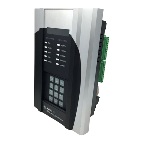
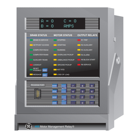
GE Multilin 469 User manual

Digital Energy
Multilin
469 Motor Management
Relay
QUICK REFERENCE GUIDE
Software Revision: 5.0x
Manual P/N: 1601-0153-A5
Manual Order Code: GEK-106493D
Copyright © 2009 GE Multilin
GE Multilin
215 Anderson Avenue, Markham, Ontario
Canada L6E 1B3
Tel: (905) 294-6222 Fax: (905) 201-2098
Internet: http://www.GEmultilin.com
IISO9001:2000
G
E
M
U
L
T
I
L
I
N
R
E
G
I
S
T
E
R
E
D
GE Multilin's Quality
Management System is
registered to
ISO9001:2000
QMI # 005094
UL # A3775
*1601-0153-A5*


TOC TABLE OF CONTENTS
469 MOTOR MANAGEMENT RELAY – QUICK REFERENCE GUIDE TOC–1
Table of Contents
DESCRIPTION ..................................................................................................... 2
MECHANICAL INSTALLATION ...................................................................... 4
DRAWOUT CASE ................................................................................................................... 4
MOUNTING ........................................................................................................................... 4
UNIT WITHDRAWAL ............................................................................................................. 6
UNIT INSERTION ................................................................................................................... 7
ELECTRICAL INSTALLATION ......................................................................... 8
RATINGS AND POLARITIES: .................................................................................................. 9
DIGITAL INPUTS: ................................................................................................................... 9
ANALOG INPUTS AND OUTPUTS ......................................................................................... 9
ACCESSING SETPOINTS VIA THE FRONT PANEL ...................................... 11
TYPICAL APPLICATION SETUP ...................................................................... 12
SYSTEM SETUP FOR PHASE, NEUTRAL AND GROUND CTS............................................. 12
SYSTEM SETUP FOR VTS..................................................................................................... 12
DIGITAL INPUT SETPOINTS .................................................................................................. 13
PROTECTION SETPOINTS ..................................................................................................... 13
COMMUNICATING WITH THE RELAY
VIA THE FRONT PANEL RS232 PORT ............................... 14
CONNECTING ENERVISTA 469 SETUP SOFTWARE WITH THE 469 ........ 15
CONFIGURING AN RS232 CONNECTION ......................................................................... 15
USING THE QUICK CONNECT FEATURE ............................................................................ 16
CONFIGURING ETHERNET COMMUNICATIONS ................................................................. 17
CONNECTING TO THE RELAY .............................................................................................. 18
WORKING WITH SETPOINTS .......................................................................... 20
ENGAGING ADEVICE ........................................................................................................... 20
ENTERING SETPOINTS .......................................................................................................... 20
WORKING WITH SETPOINT FILES ................................................................. 22
FILE SUPPORT ....................................................................................................................... 22
SETPOINTS FILES OVERVIEW ............................................................................................... 22
DOWNLOADING AND SAVING SETPOINTS FILES ............................................................... 23
ADDING SETPOINTS FILES TO THE ENVIRONMENT ........................................................... 23
CREATING ANEW SETPOINT FILE ....................................................................................... 24
UPGRADING SETPOINT FILES TO ANEW REVISION .......................................................... 24
PRINTING SETPOINTS AND ACTUAL VALUES ..................................................................... 25
LOADING SETPOINTS FROM AFILE ..................................................................................... 26
UPGRADING RELAY FIRMWARE ................................................................... 28
DESCRIPTION ........................................................................................................................ 28
SAVING SETPOINTS TO AFILE ............................................................................................. 28
LOADING NEW FIRMWARE .................................................................................................. 28
ADVANCED ENERVISTA 469 SETUP FEATURES ........................................ 31
TRIGGERED EVENTS ............................................................................................................. 31
WAVEFORM CAPTURE (TRACE MEMORY) ........................................................................... 31
PHASORS .............................................................................................................................. 33
TRENDING (DATA LOGGER) ................................................................................................. 35
EVENT RECORDER ................................................................................................................ 37
MODBUS USER MAP ............................................................................................................ 38
VIEWING ACTUAL VALUES ................................................................................................... 39
APPLICATION EXAMPLE ................................................................................. 42
DESCRIPTION ........................................................................................................................ 42
POWER SYSTEM DATA ........................................................................................................ 46
MOTOR DATA ....................................................................................................................... 47

TOC–2 469 MOTOR MANAGEMENT RELAY – QUICK REFERENCE GUIDE
TABLE OF CONTENTS
MOTOR OPERATING CURVES ............................................................................................. 47
CONTROL SYSTEM REQUIREMENTS ................................................................................... 48
CONTACT OUTPUTS ............................................................................................................. 48
RTDS..................................................................................................................................... 48
INSTRUMENT TRANSFORMER DATA ................................................................................... 48
Voltage Transformers: .............................................................................................48
Phase CTs: .....................................................................................................................48
Ground CT: ....................................................................................................................49
Motor FLC: .....................................................................................................................49
MOTOR PROTECTION .......................................................................................................... 49
Overload Pickup: ........................................................................................................49
Overload Curve: ..........................................................................................................49
Short Circuit Trip: ........................................................................................................49
Ground Fault: ...............................................................................................................49
Unbalance Alarm and Trip: ...................................................................................50
Stopped and Running Cool Times: .....................................................................50
Acceleration Trip: .......................................................................................................50
Enable Start Inhibit: ..................................................................................................50
Starts/Hour: ..................................................................................................................50
Time Between Starts: ...............................................................................................50
Stator RTDs: ..................................................................................................................50
Bearing RTDs: ..............................................................................................................51
Unbalance Bias Of Thermal Capacity: .............................................................51
Unbalance Bias K Factor: .......................................................................................51
Hot/Cold Curve Ratio: ..............................................................................................51
Enable RTD Biasing: ..................................................................................................51
RTD Bias Minimum: ...................................................................................................51
RTD Bias Mid Point: ...................................................................................................51
RTD Bias Maximum: ..................................................................................................52
SYSTEM SETPOINTS ............................................................................................................. 52
DIGITAL INPUTS SETPOINTS ............................................................................................... 54
THERMAL MODEL SETPOINTS ............................................................................................ 55
CURRENT ELEMENTS SETPOINTS ....................................................................................... 55
MOTOR STARTING SETPOINTS ........................................................................................... 57
RTD TEMPERATURE SETPOINTS ........................................................................................ 57
UNDERVOLTAGE PROTECTION: .......................................................................................... 58
Other Considerations: ..............................................................................................58
INSTALLATION: ...................................................................................................................... 59

469 MOTOR MANAGEMENT RELAY – QUICK REFERENCE GUIDE 1
469 Motor Management Relay
Quick Reference Guide
Digital Energy
Multilin
Quick Reference Guide
This Quick Reference Guide takes you through the installation and setup of your GE
Multilin 469 Motor Management Relay, and helps you get setup and running as quickly as
possible. The following topics are covered:
• Installing the 469 relay
• Installing the EnerVista 469 Setup software
• Configuring the 469 relay
This guide contains only basic instructions. For complete information, refer to GE
publication GEK-106474C: 469 Motor Management Relay Instruction Manual.

2469 MOTOR MANAGEMENT RELAY – QUICK REFERENCE GUIDE
QUICK REFERENCE GUIDE
1Description
The 469 Motor Management Relay is a microprocessor-based relay designed for the
protection and management of medium and large horsepower motors and driven
equipment. The 469 is equipped with six (6) output relays for trips, alarms, and start blocks.
Motor protection, fault diagnostics, power metering, and RTU functions are integrated into
one economical drawout package.
Typical applications include: pumps, fans, compressors, mills, shredders, extruders,
debarkers, refiners, cranes, conveyors, chillers, crushers, and blowers. Some of the
protection highlights are detailed here; a complete list is shown below.
Four assignable digital inputs may be configured for a number of different features
including tachometer or generic trip and alarm with a programmable name. The thermal
model incorporates unbalance biasing, RTD feedback, and exponential cooling. In addition
to the 15 standard overload curves, there is a custom curve feature and a curve
specifically designed for the starting of high inertia loads (where the acceleration time
exceeds the safe stall time). A second overload curve is provided for two-speed motors.
Ground faults or earth leakage as low as 0.25 A may be detected using the GE Multilin
50:0.025 ground CT. CT inputs for phase differential protection are also provided. The 12
RTD inputs provided may be individually field programmed for different RTD types. Voltage
transformer inputs allow for numerous protection features based on voltage and power
quantities. Four 4 to 20 mA analog inputs may be used for tripping and alarming on any
transducer input such as vibration, pressure, flow, etc.
Each relay provides protection, control, and monitoring functions with both local and
remote human interfaces. They also display the present trip/alarm conditions, and
measured system parameters. Recording of past trip, alarm or control events, maximum
demand levels, and energy consumption is also performed.
To aid new users in getting basic protection operating quickly, setpoints are set to typical
default values and advanced features are disabled. These settings can be reprogrammed
at any time.

QUICK REFERENCE GUIDE
469 MOTOR MANAGEMENT RELAY – QUICK REFERENCE GUIDE 3
Programming can be accomplished via the front panel. To simplify programming and
provide a more intuitive interface, setpoints can also be entered with a PC running the no-
charge EnerVista 469 setup software provided with the relay. Actual values and setpoints
can be displayed, altered, stored, and printed. If settings are stored in a setpoint file, they
can be downloaded at any time to the front panel program port of the relay via a
computer cable connected to the serial port of any personal computer.
Table 1: Summary of Protection, Control & Monitoring Functions
ANSI DESCRIPTION
51 Overload
86 Overload lockout
66 Starts/hour and Time between starts
--- Restart block (Anti-backspin timer)
50 Short circuit and Short circuit backup
--- Mechanical jam
37 Undercurrent/Underpower
32 Reverse power
46 Current unbalance
50G/51G Ground fault and Ground fault backup
87 Differential
--- Acceleration
49 Stator RTD
38 Bearing RTD
--- Other RTD and Ambient RTD
--- Open RTD alarm
--- Short/Low RTD
27/59 Undervoltage/Overvoltage
47 Phase reversal
81 Frequency
--- Reactive power
55/78 Power factor
--- Analog input
--- Demand alarm: A, kW, kvar, and kVA
--- 469 self-test, Service
--- Trip coil supervision
--- Welded contactor
--- Breaker failure
--- Remote switch
14 Speed switch and Tachometer trip
--- Load shed switch
--- Pressure switch
--- Vibration switch
19 Reduced voltage start
48 Incomplete sequence (Reduced voltage
start)
--- Remote start/stop
--- Overtorque
--- Forced relay operation

4469 MOTOR MANAGEMENT RELAY – QUICK REFERENCE GUIDE
QUICK REFERENCE GUIDE
2 Mechanical installation
2.1 Drawout case
The 469 is packaged in the standard SR-series arrangement, which consists of a drawout
relay and a companion case. The case provides mechanical protection for the drawout
portion and is used to make permanent electrical connections to external equipment.
Where required, case connectors are fitted with mechanisms, such as automatic CT
shorting, to allow the safe removal of the relay from an energized panel. There are no
electronic components in the case.
FIGURE 2: Case Dimensions
2.2 Mounting
The 469 can be mounted alone or adjacent to another SR-series unit on a standard 19-
inch rack panel. The dimensions of the panel cutout are shown below. When planning the
location of the panel cutout, ensure provision is made for the front door to swing open
without interference to or from adjacent equipment.

QUICK REFERENCE GUIDE
469 MOTOR MANAGEMENT RELAY – QUICK REFERENCE GUIDE 5
FIGURE 3: Single and double unit panel cutouts
Before mounting the 469 in the supporting panel, remove the unit from the case.
From the front of the panel, slide the empty case into the cutout. To ensure the front bezel
sits flush with the panel, apply pressure to the bezel front while bending the retaining tabs
90°. These tabs are located on the sides and bottom of the case and appear as shown
below. After bending all tabs, the case will be securely mounted and the relay can be
inserted. The SR unit is now ready for panel wiring.
FIGURE 4: Mounting Tabs
808704A1.CDR

6469 MOTOR MANAGEMENT RELAY – QUICK REFERENCE GUIDE
QUICK REFERENCE GUIDE
2.3 Unit withdrawal
Turn off control power before drawing out or reinserting the relay to prevent
maloperation!
If an attempt is made to install a relay into a non-matching case, the case's
configuration pin will prevent full insertion. Applying a strong force in this instance will
result in damage to the relay and case.
To remove the unit from the case:
1. Open the door by pulling from the top or bottom of its right side. It will rotate to the left
about its hinges.
2. Press upward on the locking latch, which is located below the handle, and hold in its
raised position. The tip of a small screwdriver may prove helpful in this operation.
FIGURE 5: Press latch up and pull handle
3. With the latch raised, pull the center of the handle outward. Once disengaged,
continue rotating the handle up to the stop position.
FIGURE 6: Rotating handle to stop position
4. When the stop position is reached, the locking mechanism will release. The relay will
now slide out of the case when pulled from its handle. To free the relay, it may
sometimes be necessary to adjust the handle position slightly.

QUICK REFERENCE GUIDE
469 MOTOR MANAGEMENT RELAY – QUICK REFERENCE GUIDE 7
2.4 Unit insertion
To insert the unit into the case:
1. Ensure that the model number on the left side of the relay matches the requirements
of the installation.
2. Raise the locking handle to the highest position.
3. Hold the unit immediately in front of the case and align the rolling guide pins (near the
hinges of the relay's handle) with the case's guide slots.
4. Slide the unit into the case until the guide pins on the unit have engaged the guide
slots on either side of the case.
5. Once fully inserted, grasp the handle from its center and rotate it down from the
raised position towards the bottom of the relay.
6. Once the unit is fully inserted the latch will be heard to click, locking the handle in the
final position. The unit is mechanically held in the case by the handle rolling pins,
which cannot be fully lowered to the locked position until the electrical connections
are completely mated.
Note No special ventilation requirements need to be observed during the installation of the
unit. The unit does not require cleaning.
FIGURE 7: Sliding the unit into the case

8469 MOTOR MANAGEMENT RELAY – QUICK REFERENCE GUIDE
QUICK REFERENCE GUIDE
3 Electrical installation
FIGURE 8: Typical wiring diagram
Get familiarized with the Installation Section of this manual. Make sure that the relay is
properly connected, paying special attention to the following:

QUICK REFERENCE GUIDE
469 MOTOR MANAGEMENT RELAY – QUICK REFERENCE GUIDE 9
3.1 Ratings and polarities:
• Control voltage matches the ratings and polarities of the relay power supply. Control
power supplied to the relay must match the installed power supply range. All grounds
must be connected for normal operation regardless of control power supply type. The
label found on the left side of the relay specifies its order code or model number. The
installed power supply's operating range will be one of the following:
LO: 20 to 60 V DC or 20 to 48 V AC
HI: 88 to 300 V DC or 70 to 265 V AC
• The relay ground connections should be connected directly to the ground bus, using
the shortest practical path. A tinned copper, braided, shielding and bonding cable
should be used. As a minimum, 96 strands of number 34 AWG should be used. Belden
catalog number 8660 is suitable.
• Current transformer input ratings and polarities match the secondary ratings of the
corresponding CT. For the correct operation of many relay features, the instrument
transformer polarities shown Figure 8: on page 8 must be followed.
Note IMPORTANT: The phase and ground current inputs will correctly measure to 20 times the
current input's nominal rating.
• The phase sequence is user programmable to be either ABC or ACB rotation.
• Voltage transformer input ratings match the secondary ratings of the VT. The 469
relays have four channels for AC voltage inputs, each with an isolating transformer.
The nominal secondary voltage must be in the 50 to 240 V range. The three phase
inputs are designated as the ‘bus voltage’. The Bus VT connections most commonly
used, delta (or open delta), is shown in Figure 8: on page 8. Be aware that these voltage
channels are internally connected as wye. This is why the jumper between the phase B
terminal and the Vcom terminal must be installed with a delta connection.
3.2 Digital inputs:
• Digital inputs are connected as indicated below. Ensure correct polarity and do not
connect any logic input circuits to ground or else relay hardware may be damaged.
FIGURE 9: Dry and wet contact connections
3.3 Analog inputs and outputs
• Analog outputs are connected as indicated in Figure 8: on page 8. Also refer the
following figure. Note that the shield of the cable shall be grounded at one point only,
usually at the PLC/computer end only.

10 469 MOTOR MANAGEMENT RELAY – QUICK REFERENCE GUIDE
QUICK REFERENCE GUIDE
FIGURE 10: Analog outputs connection
• Analog inputs are connected as indicated in Figure 8: on page 8. Also refer to the
figure below. Note that the shield of the cable shall be grounded at one point only,
usually at the 469 end only.
FIGURE 11: Analog inputs connection

QUICK REFERENCE GUIDE
469 MOTOR MANAGEMENT RELAY – QUICK REFERENCE GUIDE 11
4 Accessing setpoints via the front panel
Refer to the Changing setpoints section in Chapter 1 of the 469 Instruction Manual. Note
that to have access to the relay setpoints, you must install a hardware jumper across
terminals C1 and C2 at the back of the relay case. Attempts to enter a new setpoint
without this electrical connection will result in an error message. Important additional
information is provided in the same section regarding passcode, and accessing
information via the serial ports of the relay.

12 469 MOTOR MANAGEMENT RELAY – QUICK REFERENCE GUIDE
QUICK REFERENCE GUIDE
5 Typical application setup
The relay leaves the factory with setpoints programmed to default values, and it is these
values that are shown in all the setpoint message illustrations. Many of these factory
default values can be left unchanged.
At a minimum, the S2 SYSTEM SETUP setpoints must be entered for the system to function
correctly. To safeguard against the installation of a relay whose setpoints have not been
entered, the “Warning, 469 Not Programmed” self-test warning is displayed. In addition,
the 5 Block Start relay will be energized, and the “469 In Service” LED will be off. Once the
relay programming is complete, the relay should be in the Service state.
For a typical example on how to set the 469 for motor protection, refer to the “Application
Example” on page 42. In addition to providing typical wiring diagrams, the example covers
the procedure to set the following features of the 469:
5.1 System setup for phase, neutral and ground CTs
• CT primary ratings
• CT secondary ratings
• CT turn ratio
5.2 System setup for VTs
• VT primary ratings
• VT secondary ratings
• VT turn ratio
Setpoints can be accessed with the EnerVista 469 setup software. To access the setpoints
listed above, select the Setpoints > System Setup > Current Sensing, Setpoints > System
Setup > Voltage Sensing, and Setpoints > System Setup > Power System menu items.

QUICK REFERENCE GUIDE
469 MOTOR MANAGEMENT RELAY – QUICK REFERENCE GUIDE 13
5.3 Digital input setpoints
• Digital input identification
• Digital input asserted logic
• Digital input functionality
To set Digital Inputs by means of the EnerVista 469 setup software, select the Setpoints >
Digital Inputs menu item. The setpoints can be found as sub-pages of the following tree:
5.4 Protection setpoints
Refer to the “Application Example” on page 42 for details on how to set the 469 Motor
Management Relay for a typical motor.
The EnerVista 469 setup software can be used to set the current related protection
elements through the Setpoints > Protection > Current Elements menu item. The
setpoints will appear as tabs in the corresponding window:
A similar process can be followed to enable other protection and control feature. For a
complete setpoints list, and for additional information refer to chapter 5 of the 469
Instruction Manual.

14 469 MOTOR MANAGEMENT RELAY – QUICK REFERENCE GUIDE
QUICK REFERENCE GUIDE
6 Communicating with the relay via the front panel RS232 port
To speed up the process of changing or loading relay setpoints, the use of a computer is
strongly recommended. Refer to the 469 Instruction Manual for additional information on
the serial communication cable to be used to communicate with the relay via the front
port.
FIGURE 12: RS232 Connection

QUICK REFERENCE GUIDE
469 MOTOR MANAGEMENT RELAY – QUICK REFERENCE GUIDE 15
7 Connecting EnerVista 469 Setup software with the 469
This section is intended as a quick start guide to using the EnerVista 469 Setup software.
7.1 Configuring an RS232 connection
Before starting, verify that the serial cable is properly connected to either the RS232 port
on the front panel of the device (for RS232 communications) or to the RS485 terminals on
the back of the device (for RS485 communications).
This example demonstrates an RS232 connection. For RS485 communications, the GE
Multilin F485 converter will be required. Refer to the F485 manual for additional details. To
configure the relay for Ethernet communications, refer to “Configuring Ethernet
communications” on page 17.
1. Install and start the latest version of the EnerVista 469 Setup software (available from
the EnerVista CD or online from http://www.GEmultilin.com)
2. Click on the Device Setup button to open the Device Setup window and click the Add
Site button to define a new site.
3. Enter the desired site name in the Site Name field. If desired, a short site description
can also be entered along with the display order of devices defined for the site. In this
example, we will use “Pump Station 1” as the site name. Click the OK button when
complete.
4. The new site will appear in the upper-left list in the EnerVista 469 Setup window.
5. Click the Add Device button to define the new device.
6. Enter the desired name in the Device Name field and a description (optional) of the
site.
7. Select “Serial” from the Interface drop-down list. This will display a number of
interface parameters that must be entered for proper RS232 functionality.
8. Enter the relay slave address and COM port values (from the S1 469 SETUP ZSERIAL
PORTS menu) in the Slave Address and COM Port fields.

16 469 MOTOR MANAGEMENT RELAY – QUICK REFERENCE GUIDE
QUICK REFERENCE GUIDE
9. Enter the physical communications parameters (baud rate and parity) in their
respective fields. Note that when communicating to the 469 from the front port, the
default communications settings are: baud rate = 9600, slave address = 1, parity =
none, bits = 8, and stop bits = 1. These values cannot be changed.
10. Click the Read Order Code button to connect to the 469 device and upload the order
code. If a communications error occurs, ensure that the 469 serial communications
values entered in the previous step correspond to the relay setting values.
11. Click OK when the relay order code has been received. The new device will be added
to the Site List window (or Online window) located in the top left corner of the main
EnerVista 469 Setup window.
The 469 Site Device has now been configured for serial communications. Proceed to
“Connecting to the relay” on page 18 to begin communications.
7.2 Using the Quick Connect feature
The Quick Connect button can be used to establish a fast connection through the front
panel RS232 of a 469 relay. The following window will appear when the Quick Connect
button is pressed:
As indicated by the window, the Quick Connect feature will quickly connect the EnerVista
469 setup software to the 469 front port with the following value: 9600 baud, no parity, 8
bits, and 1 stop bit. Select the PC communications port connected to the relay and press
the Connect button.
The EnerVista 469 Setup software will display a window indicating the status of the
communications with the relay. When connected, a new site called “Quick Connect” will
appear in the Site List window. The properties of this new site cannot be changed.
Table of contents
Other GE Relay manuals