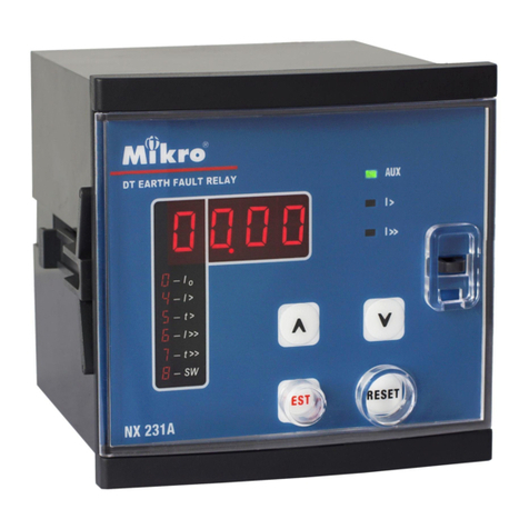
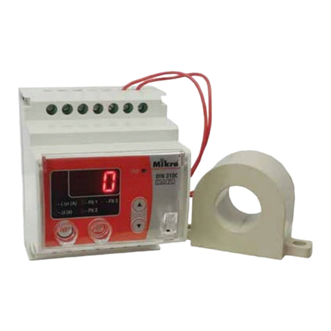
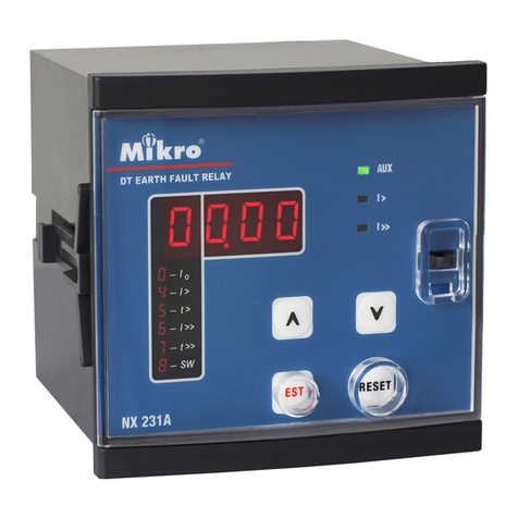
Mikro x20 User manual

user manual
X20
EARTH FAULT RELAY

2
EARTH FAULT RELAY
Ver 1.00

3
3
Table of Contents
Table of Contents 3
1.0 Introduction 5
1.1 Symbols and Definitions .......................................................... 6
1.2 Dimension of X20 ................................................................. 7
2.0 Installation 8
2.1 Mounting .......................................................................... 8
2.2 Terminal Connection ............................................................ 11
2.3 Wiring ............................................................................ 12
3.0 Display 14
3.1 Keypad ........................................................................... 14
3.2 LEDs ............................................................................. 15
4.0 Function 16
4.1 Main Page ....................................................................... 16
4.2 Menu ............................................................................. 17
4.3 Sub Menu ........................................................................ 18
4.3.1 Measurement Menu ............................................................................................................18
4.3.2 Records Menu .....................................................................................................................18
4.3.3 Configuration Menu ............................................................................................................19
4.3.4 Protection G1 & G2 Menu ..................................................................................................22
4.3.5 Input Menu ..........................................................................................................................23
4.3.6 Output Menu .......................................................................................................................25
4.3.7 Communication Menu ........................................................................................................26
5.0 Password 27
6.0 Technical Data 28
6.1 Ratings ........................................................................... 28
6.2 Records .......................................................................... 29
6.3 Setting Ranges ................................................................... 29
6.4 Measurement Range ............................................................. 30
6.5 Accuracy ......................................................................... 31
6.6 Insulation Test ................................................................... 31
6.7 EMC Standard Test .............................................................. 31
6.8 Environmental Conditions ...................................................... 32
7.0 MODBUS Protocol 33
7.1 MODBUS Functions ............................................................ 33
7.2 MODBUS Register .............................................................. 36
7.3 MODBUS Mapping Format .................................................... 43
Table of Contents

4
Appendix A – IDMT Curves 45
Normal Inverse ...................................................................... 45
Very Inverse ......................................................................... 46
Normal Inverse 1.3/10 ............................................................... 47
Long-time Inverse ................................................................... 48
Extremely Inverse ................................................................... 49

5
5
1.0 Introduction
Introduction
Mikro X20 is designed to provide protection of one non-
directional earth-fault element. This element is connected to
protection current transformer that has 5A rated CT on
secondary part.
Mikro X20 provides the user with 2x16 LCD for displaying
its various measurement parameter such as: Current
Measurement, Fault Records, Event Records, Settings and
others.
The relay extends its connectivity by adopting the Modbus-
RTU protocol. Through the use of RS485 standard protocol,
the user will be able to network the relay with other slave
device that links to a center monitoring station.
Mikro X20 provides 2 configurable output relays that can be
activated by any of the protection functions available in the
relay. There is another output relay which is used for internal
fault indication. Besides that, Mikro X20 also provides 1
configuration logic input for various functions.
1.0 Introduction

6
1.1 Symbols and Definitions
In this manual and on the relay, unless the context otherwise
requires, the following symbols and abbreviations shall apply
throughout:
AC : Alternating Current
Alternating Current
ACK : Acknowledge
Acknowledge
Alrm : Alarm Alarm
CT : Current Transformer
Current Transformer
Chg : Change
CLPU : Cold Load Pickup
DC : Direct Current
Dmnd : Demand
EF : Earth Fault
Gentrl : General
IDMT : Inverse Definite
Minimum Time
Io/IN : Earth Fault Current
Invrse : Inverse
Ip : Input
IRF : Internal Relay
Failure
LED : Light Emitting
Diodes
OC : Overcurrent
OL : Overload
PU : Pickup
RCRD : Record
Rmote : Remote
Rst : Reset
Strt : Start
Thml : Thermal

7
7
1.2 Dimension of X20
96mm
96mm
125mm
105mm
Front
View
Side
View

8
2.0 Installation
Installation guide
Before installing the X20, please check that the environment
meets the following conditions:
- Operating temperature: -5°C to +55°C
- Humidity: 56 days at 93%, 40°C non-condensing
- Dust free environment away from electrical noise and
radiation.
2.1 Mounting
a) Insert the X20 through a 91mm x 91mm switch-gear panel
as shown below:
2.0 Installation
Panel
Cutout
91mm +/- 0.5mm
91mm +/- 0.5mm

9
9
b) Slide the retainer clip along the slots on both sides of the
X20 until the device is tightly secured on the switch-gear
panel. The retainer clip can be removed by lifting the tab
lightly at the handle end.
Retainer Clip
Slide the retainer
clips along upper
and bottom slots

10
c) There are two methods to open door cover, refer below:
Method 1:
Open cover from
right slot
Method 2:
Open cover from
left slot

11
11
2.2 Terminal Connection
Connection
Terminal Function Description
1 Auxiliary supply input
2 Auxiliary supply input
3 Normally close contact for tripping contact R1
4 Normally open contact for tripping contact R1
5 Common contact for tripping contact R1
6 Common contact for tripping contact R2
7 Normally open contact for tripping contact R2
8 Normally close contact for tripping contact R2
9 Normally close contact for IRF contact
10 Normally open contact for IRF contact
11 Common contact for IRF contact
12-14 Reserved
15 5A CT input for ILo
16 5A common CT input for ILo
17 RS485 common terminal
18 RS485 negative terminal
19 RS485 positive terminal
20 Termination resistor for RS485
21-22 Reserved
23-24 Digital input (no polarity)

12
2.3 Wiring
With 3 phase 4 wires

13
13
With 3 phase 3 wires

14
3.0 Display
a) Trip LED Indication
b) Alarm LED Indication
c) 2x16 LCD Display
d) “ESC” Button
e) “UP” Button
f) “DOWN” Button
g) “ENTER” Button
h) “CLEAR” Button
i ) “RECORD” Button
j ) AUX LED Indication
3.1 Keypad
Up, Down, Enter and Esc are used to navigate through the
menus and adjust the settings.
ESC : To exit from menus, submenus or to cancel setting
value change. Press and hold for 1.5 seconds to
return to default display from any submenu.
UP : Scroll up the menus or increase setting value.
Down : Scroll down the menus or decrease setting value.
Enter : To enter submenus or to confirm setting value
change.
3.0 Display
c
g
h
i
a
b
d
e
f
j

15
15
Clear : To reset tripping, reset latched relay. If “CLEAR”
Scroll is enabled (under Configurations->Display
menu) and during alarm status, it can be used to
scroll through Earth Fault settings, and to return to
default display from any submenu if pressed and
hold for 1.5 seconds.
Record : To display Alarm records. To display successive
records, press Record key again.
3.2 LEDs
Trip LED : Indicates tripping
Alarm LED : Blinks to indicate non acknowledge alarm (or
tripping). Steady on when the alarm is
acknowledged by pressing any key.

16
4.0 Function
Figure below shows menu map for X20. It includes the
setting, input status, output status and measurement display
for X20. These menus can be accessed by pressing ESC, UP,
DOWN, ENTER, CLEAR and RECORD buttons.
4.1 Main Page
ILo:0.00
Up Down
Output 1 2
0 0
Input 1
0
Date XX/XX/XX
Time XX:XXam
Up Down
Up Down
Esc
Esc
E
n
t
e
r
Refer to 4.2 Setting
Menu
4.0 Function

17
17
4.2 Menu
IL1:0.00 IL2:0.00
IL3:0.00 ILo:0.00
1.MEASUREMENTS
Esc Enter
2.RECORDS
Up Down
3.CONFIGURATION
Up Down
4.PROTECTION G1
Up Down
5.PROTECTION G2
Up Down
6.INPUT
Up Down
7.OUTPUT
Up Down
8.COMMUNICATION
Up Down
Esc
Enter
Esc
Enter
Esc
Enter
Esc
Enter
Esc
Enter
Esc
Enter
Esc
Enter
Esc
Enter
Refer to 4.3.1
Refer to 4.3.2
Refer to 4.3.3
Refer to 4.3.4
Refer to 4.3.4
Refer to 4.3.5
Refer to 4.3.6
Refer to 4.3.7
Esc

18
*If user request to change setting, press Enter button.
4.3 Sub Menu
4.3.1 Measurement Menu
LCD Display
Description
Ilo Earth current value. Taking into account of Line
CT Pri Ratio.
Ilo Max Peak Earth current value.
Ilo Avg Average Earth current value.
Max&Avg I
RST
To clear the maximum and average values of the
currents. Press Clear button to clear these values.
Time
Window
Set the value for the time window (rolling)
during which maximum and average values are
stored. Press Enter to change the value.
4.3.2 Records Menu
4.3.2.1 Fault Records
Whenever any trip fault happens in X20, information of trip
value, element, source, date, time and Earth fault magnitude
value will be stored in fault records. There is total 50 fault
records storage available in X20.
4.3.2.2 Event Records
Whenever any event has done in X20, information of type
event, date and time will be stored in event records. As
examples of type events are like setting change, Aux power
start, clear trip fault and others more. There is total 250 event
records storage available in X20.

19
19
*If user request to change setting, press Enter button.
4.3.3 Configuration Menu
4.3.2.1 Op parameter Menu
LCD Display Description
Password This password is required when changing relay
settings.
Description Model name of this relay
Firmware Version of the firmware
Frequency Set the nominal value of the line frequency
4.3.2.2 CT Ratio Menu
LCD Display Description
E/Gnd CT Pri Set the rated primary current of the Earth/Ground
CT.
Note: The CT secondary should be connected to 5A CT input
terminal of the relay according to Primary CT type. The display
current is calculated by the formula:
Current at CT input terminal / CT input terminal type x CT Pri
(setting above)
For example if:
Current at CT input terminal = 3A,
CT input terminal type = 5A,
CT Pri = 200A,
The display value = 3/5 x 200 = 120A

20
4.3.2.3 Date & Time Menu
LCD Display Description
Date Set the date.
Date Format Set the date format for display
Time Set the time.
Time Format Set the time format for display.
4.3.2.4 Group Select Menu
LCD Display Description
Chg Group
by…
Set whether the protection group setting is
changed by Menu or Input. One of the input
functions must be set to 'Select Group" if Input
is selected
Setting
Group1
If above is set to Menu, this will set the active
protection group
4.3.2.5 Display Menu
LCD Display Description
LCD On
Time
Set how long the LCD backlight remains on after
no key is pressed.
LCD
Brightness Set the brightness of the LCD backlight.
"CLEAR"
Scroll?
Set if Clear key can be used to scroll throught the
default display pages and Earth OC settings
*If user request to change setting, press Enter button.
Table of contents
Other Mikro Relay manuals

